多体动力学 pdf
- 格式:docx
- 大小:12.10 KB
- 文档页数:1
多体系统动力学考查试题
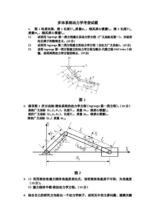
1.图1均质双摆,摆1长度2l1,质量m1,绕其质心惯量I1;摆2长度2l2,
质量m2,绕其质心惯量I2;
1)试利用lagrange第一类方程建立其动力学方程(广义坐标见图一),并说明拉氏乘子的物理含义。
(10分)
2)试利用lagrange第二类方程建立其动力学方程(自定义广义坐标)。
(10分) 3)说明lagrange第一类方程建立的动力学方程为微分-代数方程DAE Index 3问题,说明两类动力学方程的特点。
(10分)
图1
2.推导图2 所示曲柄-滑块系统的动力学方程(lagrange第一类方程)。
(20分)
曲柄广义坐标(x1,y1,θ1),长度2l1,质量m1,绕质心惯量I1;
连杆广义坐标(x2,y2,θ2),长度2l2,质量m2,绕质心惯量I2;
滑块广义坐标(x3)质量m3;
图2
3.1)利用欧拉角建立刚体角速度表达式,说明刚体角速度不可积,为伪速度
(10分);
2)建立刚体牛顿-欧拉动力学方程。
(10分)
4.结合自己的研究方向给出一个动力学例子,说明其中的主要问题、建模关键
及其目前的研究状态。
(30分)。

多体系统动力学简介多体系统动力学研究对象——机构工程中的对象是由大量零部件构成的系统。
在对它们进行设计优化与性态分析时可以分成两大类一类为结构——正常工况下构件间没有相对运动(房屋建筑,桥梁等)——关心的是这些结构在受到载荷时的强度、刚度与稳定一类为机构——系统在运动过程中这些部件间存在相对运动(汽车,飞机起落架。
机器人等)——力学模型为多个物体通过运动副连接的系统,称为多体系统多体系统动力学俄研究的对象——机构(复杂机械系统)不考虑系统运动起因的情况下研究各部件的位置与姿态及其变化速度和加速度的关系典型案例:平面和空间机构的运动分析系统各部件间通过运动副与驱动装置连接在一起数学模型:各部件的位置与姿态坐标的非线性代数方程,以及速度与加速度的线性代数方程当系统受到静载荷时,确定在运动副制约下的系统平衡位置以及运动副静反力典型案例:机车或汽车中安装有大量的弹簧阻尼器,整车设计中必须考虑系统在静止状态下车身的位置与姿态,为平稳性与操纵稳定性的研究打下基础数学模型:非线性微分代数方程组讨论载荷和系统运动的关系研究复杂机械系统在载荷作用下各部件的动力学响应是工程设计中的重要问题动力学正问题——已知外力求系统运动的问题动力学逆问题——已知系统运动确定运动副的动反力,是系统各部件强度分析的基础动力学正逆混合问题——系统的某部分构件受控,当它们按照某已知规律运动时,讨论在外载荷作用下系统其他构件如何运动数学模型:非线性微分代数方程组机械系统的多体系统力学模型在对复杂机械系统进行运动学与动力学分析前需要建立它的多体系统力学模型。
对系统如下四要素进行定义:•物体•铰链•外力(偶)•力元实际工程中的机械系统多体系统力学模型的定义取决于研究的目的模型定义的要点是以能揭示系统运动学与动力学性态的最简模型为优性态分析的求解规模与力学模型的物体与铰的个数有关物体——定义多体系统中的构件定义为物体多体系统力学模型中物体的定义并不一定与具体工程对象的零部件一一对应。

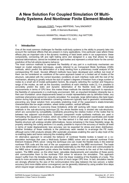
A New Solution For Coupled Simulation Of Multi-Body Systems And Nonlinear Finite Element Models Giancarlo CONTI, Tanguy MERTENS, Tariq SINOKROT(LMS, A Siemens Business)Hiromichi AKAMATSU, Hitoshi KYOGOKU, Koji HATTORI(NISSAN Motor Co., Ltd.)1 IntroductionOne of the most common challenges for flexible multi-body systems is the ability to properly take into account the nonlinear effects that are present in many applications. One particular case where these effects play an important role is the dynamic modeling of twist beam axles in car suspensions: these components, connecting left and right trailing arms and designed in a way that allows for large torsional deformations, cannot be modeled as rigid bodies and represent a critical factor for the correct prediction of the full-vehicle dynamic behavior.The most common methods to represent the flexibility of any part in a multi-body mechanism are based on modal reduction techniques, usually referred to as Component Mode Synthesis (CMS) methods, which predict the deformation of a body starting from a preliminary modal analysis of the corresponding FE mesh. Several different methods have been developed and verified, but most of them can be considered as variations of the same approach based on a limited set of modes of the structure, calculated with the correct boundary conditions at each interface node with the rest of the mechanism, allowing to greatly reduce the size of system’s degrees of freedom from a large number of nodes to a small set of modal participation factors. By properly selecting the number and frequency range of the modes, as well as the boundary conditions at each interface node [1], it is possible to accurately predict the static and dynamic deformation of the flexible body with remarkable improvements in terms of CPU time: this makes these methods the standard approach to reproduce the flexibility of components in a multi-body environment. Still, an important limitation inherently lies in their own foundation: since displacements based on modal representation are by definition linear, any nonlinear phenomena cannot be correctly simulated. For example, large deformations like twist beam torsion during high lateral acceleration cornering maneuvers typically lead to geometric nonlinearities, preventing any linear solution from accurately predicting most of the suspension’s elasto-kinematic characteristics like toe angle variation, wheel center position, vertical stiffness.One possible solution to overcome these limitations while still working with linear modal reduction methods is the sub-structuring technique [2]: the whole flexible body is divided into sub-structures, which are connected by compatibility constraints preventing the relative motion of the nodes that lie between two adjacent sub-structures. Standard component mode synthesis methods are used in formulating the equations of motion, which are written in terms of generalized coordinates and modal participation factors of each sub-structure. The idea behind it is that each sub-portion of the whole flexible structure will undergo smaller deformations, hence remaining in the linear flexibility range. By properly selecting the cutting sections it is usually possible to improve the accuracy of results (at least in terms of nodal displacements: less accuracy can be expected for stress and strain distribution). Another limitation of these methods is the preliminary work needed to re-arrange the FE mesh, although some CAE products already offer automatic processes enabling the user to skip most of the re-meshing tasks and hence reducing the modeling efforts.An alternative approach to simulate the behavior of nonlinear flexible bodies is based on a co-simulation technique that uses a Multi-body System (MBS) solver and an external nonlinear Finite Element Analysis (FEA) solver. Using this technique one can model the flexible body in the external nonlinear FEA code and the rest of the car suspension system in the MBS environment. The loads due to the deformation of the body are calculated externally by the FEA solver and communicated to the MBS solver at designated points where the flexible body connects to the rest of the multi-body system. The MBS solver, on the other hand, calculates displacements and velocities of these points and communicates them to the nonlinear FEA solver to advance the simulation. This approach doesn’t suffer from the limitations that arise from the linear modeling of the flexibility of a body. This leads to more accurate results, albeit at the price of much larger CPU time. In fact, simulation results are strongly affected by the size of the communication time step between the two solvers: a better accuracy (and more stable solver convergence) can be generally obtained by using smaller time steps which require larger calculation times, as shown also in [3].2 Overview of the activityThis paper presents the results of a benchmark activity performed in collaboration with Nissan Auto where a new FE-MBS variable-step co-simulation technique was used: a coupling at the iteration level currently implemented in commercial FEA package LMS SAMCEF Mecano [4] and general purpose multi-body system package LMS b Motion [5]. In this technique each solver uses its own integrator but only one Newton solver is used. In this case one solver is designated as the master and will be responsible for solving the Newton iterations. The coupled iterations continue until both solvers satisfy their own solution tolerances and convergence is achieved. The co-simulation process is organized by means of a supervisor code that manages the data exchange and determines the new time step of integration for both solvers. Further technical details on this “coupled simulation“ method, as well as a comparison with the variable-step co-simulation method, are available in [6].A multi-body model of a rear twist beam suspension has been created, where the flexibility of the twist beam was simulated with three alternative modeling techniques to be compared:- Component Mode Synthesis (Craig-Bampton method)- Linear sub-structuring- Nonlinear FE-MBS coupled simulation.As a further step also the two bushings connecting the twist beam with the car body, originally modeled in b Motion as standard force elements with nonlinear stiffness and damping characteristics for all directions, have been replaced by two SAMCEF Mecano nonlinear flexible bodies.Two different suspension events have been simulated in order to compare the results from the different modeling methods:- Suspension roll (opposite wheel vertical travel applied at wheel centers)- Braking in turn (dynamic loads applied at wheel centers).Figure 1 shows the b Motion suspension model used for this activity, where the FE mesh models of twist beam and bushings are also displayed:3 Modeling and simulations3.1 Model validationAs a first step a multi-body model of rear suspension was created in b Motion with input data provided by Nissan Auto from a pre-existing model developed with another multi-body software package: hardpoints location, bodies mass and inertia data, kinematic and compliant connections characteristics, properties of coil springs, shock absorbers, end stop elements. Since the original model included a flexible twist beam based on a modal reduction method (Craig-Bampton) the same original mode set has been used to obtain a linear flexible representation of the twist beam in b Motion. Then a suspension roll has been simulated in both environments in order to validate Motion results with the data from the source model, obtained by applying a vertical displacement in opposite directions at the two wheel centers. The main elasto-kinematic suspension characteristics have been compared: toe and camber variation, wheel center longitudinal and lateral displacements, vertical stiffness. In fig.2 the vertical force at wheel center and the toe angle variation are plotted versus the wheel vertical displacement: the differences between the two models are negligible.Fig. 1b Motion multi-body model of rear suspension with flexible twist beam and bushings3.2 Flexible twist beam modeling Once validated the b Motion model, the linear flexible twist beam was replaced by the two alternative modeling methods intended to take into account the geometric nonlinearities due to the large deformations of the beam element: sub-structuring and coupled simulation Motion – Mecano.- Sub-structuring: the twist beam was cut in3 sections along the central pipe, resultingin 4 separate linear flexible bodies: the twolongitudinal arms + two symmetric halves ofthe beam. Figure 3 shows the three cuttingsections used.- Coupled simulation Motion – Mecano -starting from the original Nastran FE mesh, the dynamic behavior of the full twist beam is calculated by the SAMCEF Mecano nonlinear solver through a specific Analysis Case added to the VL Motion model.3.3 FE bushings modelingAs a further task of the activity, starting from the CAD representation of the geometry of the bushings connecting the twist beam with the car body a Mecano FE model of each bushing has been created and implemented into the b Motion mechanism to replace the original bushing force elements, modeled as nonlinear stiffness and damping curves in all six directions. Material properties for the rubber and metal parts of the bushings were not known in detail, so tentative values have been used for the rubber whereas the metal parts have been considered as rigid: although these assumptions were expected to have a major impact on results, the main purpose of this task was not to obtain accurate and correlated results, rather to prove the capability of the Motion-Mecano coupled simulation method to successfully solve multiple nonlinear flexible bodies in the same model.3.4 Results comparisonFigure 4 shows the results of the suspension roll analysis for two of the most relevant outputs for the handling performance of a car: toe angle and wheel track variation, plotted vs. left wheel vertical displacement. The main outcome is that sub-structuring and coupled Motion-Mecano simulation (not including FE bushings) give very similar results, both different from the linear case: as expected, the linear approach gives reliable results only in a limited range of displacements, whereas for larger deformations of the twist beam a more accurate prediction of the behavior of the system can be obtained only by considering the nonlinear flexibility of the body.In Fig.5 some of the results from the dynamic braking-in-turn maneuver are displayed, where during a cornering maneuver started at around 0.7s a braking force is applied after 1.5s. In this comparison the additional case with the two nonlinear FE bushings is also displayed: again, a remarkable difference can be detected between the linear case and the nonlinear FE-MBS coupled simulation; furthermore a clear effect from nonlinear FE bushings can be seen, although most likely affected by uncertainties on the material properties applied in the Mecano FE bushing models.Fig. 3 Sub-structuring of the linear flexible twist beam Fig. 2Comparison of results between b Motion model and source MBS model4 ConclusionsIn this paper the usage of a new FE-MBS co-simulation technique for an automotive application is compared with two alternative solutions to represent the nonlinear flexibility of a body in a multi-body mechanism. A b Motion rear suspension model with flexible twist beam has been created with the aim to simulate two typical handling events where the proper prediction of the large deformation of the twist beam strongly affects most of the elasto-kinematic characteristics of the suspension. The compared results show a clear difference between the linear approach, based on a modal representation of the flexibility of the body, and the alternative methods which allow a more correct prediction of the geometric nonlinearity.This new b Motion – SAMCEF Mecano co-simulation technique allows also the simulation of multiple nonlinear flexible bodies in the same mechanisms as shown in this paper. Further studies are currently on-going to extend the usage of this solution to complex applications like flexible contact and friction forces, nonlinear material properties, thermal effects.5 References[1] Yoo W.S., Haug E.J.: “Dynamics of flexible mechanical systems using vibration and static correctionmodes ”, Journal of Mechanisms, Transmissions and Automation in Design, 108, 315-322, 1985[2] Sinokrot T.Z., Nembrini M., Toso A., Prescott W.C.: "A Comparison Of Sub-Structuring Synthesis And TheCosimulation Approach In The Dynamic Simulation Of Flexible Multi-body Systems ", MULTIBODYDYNAMICS 2011, ECCOMAS Thematic Conference, Brussels, Belgium, 4-7 July 2011[3] Sinokrot T.Z., Nembrini M., Toso A., Prescott W.C.: "A Comparison Of Different Multi-body SystemApproaches In The Modeling Of Flexible Twist Beam Axles ", Proceedings of the 8th International Conference on Multi-body Systems, Nonlinear Dynamics, and Control, August 28-31, 2011, Washington D.C., USA[4] LMS International, b Online Help Manual , 2013.[5] LMS Samtech, Samcef Online Help Manual – version 15.1, 2013.[6] Sinokrot T., Jetteur P., Erdelyi H., Cugnon F., Prescott W.: "A New Technique for Stronger Couplingbetween Multi-body System and Nonlinear Finite Element Solvers in Co-simulation Environments ",MULTIBODY DYNAMICS 2013, ECCOMAS Thematic Conference, Zagreb, Croatia, 1-4 July 2013Fig. 4Suspension roll analysis: toe angle and wheel track variationsFig. 5Braking-in-turn analysis: wheel base and toe angle variations。

多体系统动力学华中科技大学CAD中心张云清2010-1-6机械系统动力学计算机辅助分析多体系统动力学机械束一.机械铰链与约束方程二.运动学分析基础三.平面多体系统运动学四空间多体系统运动学四.空间多体系统运动学五.动力学分析方程两种形式六.平面多体系统动力学多体系动学七.空间多体系统动力学2010-1-6机械系统动力学计算机辅助分析机械铰链与约束方程•坐标系的分类•坐标系的变换•基本约束•平面铰链•空间铰链•自由度2010-1-6机械系统动力学计算机辅助分析•大地坐标系—惯性坐标系地坐标系坐标系•刚体固连坐标系—质心固连坐标系-主轴固连坐标系•铰链坐标系—铰链标架•力元坐标系—力元标架2010-1-6机械系统动力学计算机辅助分析cos sin θθ−⎡⎤=⎢sin cos A θθ⎥⎣⎦2010-1-6机械系统动力学计算机辅助分析基本约束•垂直1型约束•垂直2型约束2010-1-6机械系统动力学计算机辅助分析基本约束•平行1型约束•2平行型约束2010-1-6机械系统动力学计算机辅助分析平面铰链•转动铰链(Revolute Joint)•(Translational(Prismatic)Joint)平移铰链(Translational(Prismatic) Joint)2010-1-6机械系统动力学计算机辅助分析空间铰链•Spherical Joint)球铰(S h i l J i t•圆柱铰链(Cylindrical Joint)•Prismatic Joint平移铰链(Prismatic Joint)•转动铰链(Revolute Joint)2010-1-6机械系统动力学计算机辅助分析空间铰链•万向节(Universal (Hooke)Joint)向节(U i l(H k)J i •螺旋铰链(Screw Joint)2010-1-6机械系统动力学计算机辅助分析自由度•平面机构自由度2010-1-6机械系统动力学计算机辅助分析自由度•空间机构自由度2010-1-6机械系统动力学计算机辅助分析运动学分析基础•位置、速度、加速度方程•铰链的约束方程•驱动约束的方程运动学分析的计算方•运动学分析的计算方法2010-1-6机械系统动力学计算机辅助分析位置、速度、加速度方程•平面问题位置、速度、加速度方程2010-1-6机械系统动力学计算机辅助分析位置速度加速度方程位置、速度、加速度方程•空间问题位置、速度、加速度方程2010-1-6机械系统动力学计算机辅助分析位置、速度、加速度方程位置速度加速度方程•空间问题位置、速度、加速度方程2010-1-6机械系统动力学计算机辅助分析铰链的约束方程•Ground Constraints•Revolute Joint•Prismatic Joint2010-1-6机械系统动力学计算机辅助分析铰链的约束方程•Prismatic Joint2010-1-6机械系统动力学计算机辅助分析驱动约束的方程2010-1-6机械系统动力学计算机辅助分析运动学分析的计算方法2010-1-6机械系统动力学计算机辅助分析运动学分析的计算方法2010-1-6机械系统动力学计算机辅助分析平面运动学分析例子2010-1-6机械系统动力学计算机辅助分析平面运动学分析例子2010-1-6机械系统动力学计算机辅助分析平面运动学分析例子2010-1-6机械系统动力学计算机辅助分析平面运动学分析例子2010-1-6机械系统动力学计算机辅助分析平面运动学分析例子2010-1-6机械系统动力学计算机辅助分析平面运动学分析例子2010-1-6机械系统动力学计算机辅助分析•两自由度平面机械臂运动学分析•平面曲柄滑块机构运动学分析2010-1-6机械系统动力学计算机辅助分析•空间曲柄连杆机构运动学分析•空间四连杆机构运动学分析2010-1-6机械系统动力学计算机辅助分析动力学分析方程两种形式•最大量坐标形式—DAE方程•---ODE最小量坐标形式ODE方程•开闭环问题的动力学方程2010-1-6机械系统动力学计算机辅助分析最大量坐标形式—DAE方程2010-1-6机械系统动力学计算机辅助分析最大量坐标形式—DAE方程DAE2010-1-6机械系统动力学计算机辅助分析最小量坐标形式---ODE 方程2010-1-6机械系统动力学计算机辅助分析ODE 最小量坐标形式---ODE 方程2010-1-6机械系统动力学计算机辅助分析ODE 最小量坐标形式---ODE 方程2010-1-6机械系统动力学计算机辅助分析开闭环问题的动力学方程2010-1-6机械系统动力学计算机辅助分析开闭环问题的动力学方程2010-1-6机械系统动力学计算机辅助分析开闭环问题的动力学方程2010-1-6机械系统动力学计算机辅助分析平面多体系统动力学平面刚体的广义惯性力平面刚体的动力学方程受约束的平面刚体系统动力学方程受束学2010-1-6机械系统动力学计算机辅助分析平面刚体的广义惯性力cos sin sin cos A θθθθ−⎡⎤=⎢⎥⎣⎦sin cos cos sin A θθθθθ−−⎡⎤=⎢⎥−⎣⎦2010-1-6机械系统动力学计算机辅助分析平面刚体的广义惯性力2010-1-6机械系统动力学计算机辅助分析平面刚体的广义惯性力2010-1-6机械系统动力学计算机辅助分析平面刚体的广义惯性力2010-1-6机械系统动力学计算机辅助分析平面刚体的广义惯性力-质心固连坐标系2010-1-6机械系统动力学计算机辅助分析平面刚体的动力学方程2010-1-6机械系统动力学计算机辅助分析受约束的平面刚体系统动力学方程2010-1-6机械系统动力学计算机辅助分析受约束的平面刚体的动力学方程2010-1-6机械系统动力学计算机辅助分析受约束的平面刚体的动力学方程2010-1-6机械系统动力学计算机辅助分析受约束的平面刚体的动力学方程2010-1-6机械系统动力学计算机辅助分析受约束的平面刚体的动力学方程2010-1-6机械系统动力学计算机辅助分析。

第 37 卷第 4 期2024 年4 月振 动 工 程 学 报Journal of Vibration EngineeringVol. 37 No. 4Apr. 2024软式空中加油系统鞭甩现象多体动力学分析赵振军1,谭兴宇1,史晓军2,张昌荣2,郭鹏2(1.北方工业大学机械与材料工程学院,北京 100144;2.中国空气动力研究与发展中心高速空气动力研究所,四川绵阳 621000)摘要: 软管‑锥套式空中加油系统的柔性结构经常发生不同程度的软管鞭甩现象,极大影响空中加油任务的安全性。
基于柔性多体动力学,建立了空中加油系统动力学模型,其中,利用基于任意拉格朗日‑欧拉描述方式和绝对结点坐标法的索/梁模型描述管线的大变形、大范围运动以及软管收放,并对空中加油系统受到的气动力进行建模,建立的模型能够反映加油机和受油机运动、软管和锥套的变形与气动力的耦合影响。
基于建立的空中加油系统动力学模型,复现飞行状态下的软管鞭甩现象,获得了鞭甩现象的形成机理。
研究表明,对接冲击下,软管平衡状态改变所形成的剪切波向后传播与反射是鞭甩现象产生的主要原因。
通过多工况计算结果,分析了软管刚度、对接速度、Ma数各因素对鞭甩现象引起的软管剪切力、纵波与剪切波传播速度的影响规律,并分别分析了软管收放控制和加缓冲的受油插头两种措施对鞭甩现象振动抑制的有效性。
关键词: 多体动力学;空中加油;鞭甩现象;软管‑锥套组合体中图分类号: O313.7; V228.1+7 文献标志码: A 文章编号: 1004-4523(2024)04-0696-12DOI:10.16385/ki.issn.1004-4523.2024.04.016引言空中加油是飞行器在不着陆情况下,实现燃油快速补给、提升战机滞空时间、及时投入战场作战的主要技术手段。
根据加油管路方案的不同,空中加油可以分为软管式加油和硬管式加油两种方式[1],中国主要采用软管式加油方式。
软管是一根长达数十米的柔性体,在对接过程中受到多种内外部干扰因素影响,比如加油对接操纵方式、软管柔性材料、飞行Ma数、加油机尾流、姿态变化、受油机头波等[2]。


基于多体动力学和有限元法的机车车体结构疲劳仿真汇报人:日期:•项目背景与意义•多体动力学建模与分析•有限元法建模及验证目录•疲劳损伤评估方法研究•仿真结果分析与讨论•结论与展望01项目背景与意义机车车体结构包括底架、侧墙、车顶等多个部件,各部件之间相互连接,形成一个复杂的整体。
车体结构复杂机车在运行过程中需要承受各种动态载荷,如牵引力、制动力、离心力等,对车体结构的强度和刚度提出较高要求。
承载要求高长期运行和复杂载荷作用下,机车车体结构容易出现疲劳裂纹和损伤,影响行车安全和使用寿命。
疲劳问题突出机车车体结构现状及问题预测疲劳寿命通过疲劳仿真,可以预测机车车体结构在不同运行工况下的疲劳寿命,为制定检修周期和优化设计方案提供依据。
降低维修成本疲劳仿真可以帮助发现车体结构的薄弱环节,有针对性地进行改进和维护,降低维修成本和事故风险。
提高运行效率优化后的车体结构可以更好地适应复杂载荷和运行环境,提高机车的运行效率和安全性。
疲劳仿真研究价值有限元法分析采用有限元法,对机车车体结构进行静力学和动力学分析,获取结构的应力、应变和模态等参数。
多体动力学分析运用多体动力学理论,建立机车车辆系统动力学模型,分析车辆在运行过程中的动态响应和载荷特性。
联合仿真将多体动力学分析与有限元法分析相结合,实现机车车辆系统与车体结构的联合仿真,全面评估车体的疲劳性能和安全性。
多体动力学与有限元法结合应用02多体动力学建模与分析包括底架、侧墙、车顶等部件,通过连接件组成完整车体。
车体结构组成多体系统定义外部激励将车体划分为多个刚体和柔体,考虑其相互作用和运动关系。
包括轨道不平顺、轮轨接触力等,对车体产生动态激励。
030201机车车体多体系统描述03仿真软件实现利用多体动力学仿真软件,实现车体结构动态响应的数值模拟。
01运动方程建立基于牛顿第二定律和拉格朗日方程,建立车体多体系统运动方程。
02数值求解方法采用显式积分法、隐式积分法等数值方法,对运动方程进行求解。
多体动力学(Multi-Body Dynamics,简称MBD)是一门研究由多个物体组成的复杂系统运动和相互作用的科学。
这些物体可能是刚性的、柔性的,或者刚柔混合的,它们通过各种连接方式(如铰链、约束等)组合在一起,形成一个多体系统。
多体动力学在工程领域的应用非常广泛,包括机械系统设计、航空航天、车辆工程、机器人技术、生物医学工程等多个方面。
多体动力学的核心任务
数学建模:建立复杂机械系统运动学和动力学的数学模型,开发相应的软件系统,以便用户能够输入系统的基本数据后,自动进行标准化处理。
数值方法开发:研究和实现有效的数值积分方法,自动得到系统的运动学规律和动力学响应。
仿真与优化:通过计算机仿真分析系统的动态行为,进行系统性能的预测和优化。
多体动力学的关键要素
运动学:研究系统各部件的运动状态,不考虑造成这种运动的力。
动力学:研究作用在系统各部件上的力以及由此产生的运动状态。
约束和连接:描述系统各部件之间的相互作用和运动限制。
力和运动副:模拟系统中各种力的作用以及运动副(如铰链、滑块等)对运动的影响。
多体动力学的应用实例
车辆动力学仿真:分析汽车、火车等车辆在不同工况下的动态响应,优化车辆设计。
机器人运动控制:研究机器人的运动学模型,实现精确的运动控制。
航空航天器着陆分析:模拟航天器着陆过程中的冲击响应,评估着陆过程的稳定性。
生物机械系统:分析人体运动或医疗器械的动态特性,为康复医疗和器械设计提供依据。
多体动力学软件工具
常用的多体动力学仿真软件包括ADAMS(Autodesk Dynamic Analysis Modeling System)、MATLAB的SimMechanics、以及Universal Mechanism等。
这些软件工具提供了从几何建模、动力学建模到仿真分析的完整解决方案。
总结
多体动力学是一门综合性很强的学科,它不仅涉及力学的基础理论,还包括计算机科学、数值分析等多个领域的知识。
通过多体动力学的研究,工程师能够更好地理解和预测复杂系统的动态行为,为系统设计和性能优化提供科学依据。