OEM617 Datasheet(中文)
- 格式:pdf
- 大小:153.98 KB
- 文档页数:2


ADSP-BF609 EZ-KIT Lite®Evaluation System ManualRevision 1.0, March 2012Part Number82-000269-01 Analog Devices, Inc.One T echnology WayaNorwood, Mass. 02062-9106Copyright Information© 2012 Analog Devices, Inc., ALL RIGHTS RESERVED. This docu-ment may not be reproduced in any form without prior, express writtenconsent from Analog Devices, Inc.Printed in the USA.DisclaimerAnalog Devices, Inc. reserves the right to change this product withoutprior notice. Information furnished by Analog Devices is believed to beaccurate and reliable. However, no responsibility is assumed by AnalogDevices for its use; nor for any infringement of patents or other rights ofthird parties which may result from its use. No license is granted by impli-cation or otherwise under the patent rights of Analog Devices, Inc. Trademark and Service Mark NoticeThe Analog Devices logo, Blackfin, CrossCore, EZ-Board, EZ-Extender, and EZ-KIT Lite are registered trademarks of Analog Devices, Inc.All other brand and product names are trademarks or service marks oftheir respective owners.Regulatory ComplianceThe ADSP-BF609 EZ-KIT Lite is designed to be used solely in a labora-tory environment. The board is not intended for use as a consumer end product or as a portion of a consumer end product. The board is an open system design which does not include a shielded enclosure and therefore may cause interference to other electrical devices in close proximity. This board should not be used in or near any medical equipment or RF devices.The ADSP-BF609 EZ-KIT Lite is currently being processed for certifica-tion that it complies with the essential requirements of the EuropeanEMC directive 2004/108/EC and therefore carries the “CE” mark.The EZ-KIT Lite evaluation system contains ESD (electrostatic discharge)sensitive devices. Electrostatic charges readily accumulate on the humanbody and equipment and can discharge without detection. Permanent dam-age may occur on devices subjected to high-energy discharges. Proper ESDprecautions are recommended to avoid performance degradation or loss offunctionality. Store unused EZ-KIT Lite boards in the protective shippingpackage.PREFACEProduct Overview (xii)Purpose of This Manual (xv)Intended Audience (xv)Manual Contents (xvi)What’s New in This Manual (xvi)Technical or Customer Support (xvii)Supported Processors (xvii)Product Information (xviii)Analog Devices Web Site (xviii)EngineerZone (xviii)Related Documents (xix)Notation Conventions (xx)USING ADSP-BF609 EZ-KIT LITEPackage Contents .......................................................................... 1-2 ADSP-BF609 EZ-Board ................................................................ 1-3 Default Configuration ................................................................... 1-3 Supported Operating Systems ....................................................... 1-5ADSP-BF609 EZ-KIT Lite Evaluation System Manual vSystem Requirements .................................................................... 1-5 EZ-KIT Lite Installation ............................................................... 1-6 EZ-KIT Lite Session Startup ......................................................... 1-7 Evaluation License Restrictions ................................................... 1-10 Memory Map ............................................................................. 1-10 DDR2 SDRAM .......................................................................... 1-12 SPI Interface .............................................................................. 1-13 SMC Interface ............................................................................ 1-13 Ethernet Interface ....................................................................... 1-13 USB OTG HS Interface .............................................................. 1-14 CAN Interface ............................................................................ 1-14 UART Interface .......................................................................... 1-15 SD Interface ............................................................................... 1-16 Rotary Encoder Interface ............................................................ 1-16 Temperature Sensor Interface ...................................................... 1-17 Link Ports Interface .................................................................... 1-17 General-Purpose I/O (GPIO) ...................................................... 1-18 JTAG Interface ........................................................................... 1-18 Power-On-Self Test ..................................................................... 1-20 Expansion Interface III ............................................................... 1-20 Power Architecture ..................................................................... 1-21 Power Measurements .................................................................. 1-21 Example Programs ...................................................................... 1-22 Reference Design Information ..................................................... 1-22vi ADSP-BF609 EZ-KIT Lite Evaluation System ManualADSP-BF609 EZ-KIT LITE HARDWARE REFERENCE System Architecture ...................................................................... 2-2 Software-Controlled Switches (SoftConfig) .................................... 2-3 Overview of SoftConfig ........................................................... 2-3SoftConfig on the ADSP-BF609 EZ-KIT LITE ...................... 2-7Programming SoftConfig Switches ........................................... 2-8 Push Buttons and Switches .......................................................... 2-17 JTAG Interface Switches (SW1, SW3–5) ................................ 2-18Boot Mode Select Switch (SW2) ............................................ 2-19IRQ/Flag Enable Switches (SW6–7) ....................................... 2-20Reset Switch (SW8) ............................................................... 2-20Rotary Encoder With Momentary Switch (SW9) .................... 2-20Wake Push Switch (SW10) .................................................... 2-21 Power Jumpers ............................................................................ 2-21 LEDs .......................................................................................... 2-22 GPIO LEDs (LED1–4) ......................................................... 2-23Thermal Limit LED (LED5) ................................................. 2-23Power LED (LED6) ............................................................... 2-23Reset LED (LED7) ................................................................ 2-24SPD LED (LED6) ................................................................. 2-24 Connectors ................................................................................. 2-24 DCE UART Connector (J2) .................................................. 2-25Link Port /JTAG Connectors (J3 and P8) ............................... 2-25JTAG Connector (P1) ........................................................... 2-25 ADSP-BF609 EZ-KIT Lite Evaluation System Manual viiJTAG Connector (ZP1) ......................................................... 2-26Expansion Interface III Connectors (P1A–C, P2A, P3A) ........ 2-26USB Connector (P7) ............................................................. 2-26Power Connector (P18) ......................................................... 2-26CAN Connector (J4) ............................................................ 2-27SD Connector (J5) ................................................................ 2-27Ethernet Connector (J1) ....................................................... 2-27Ethernet Connectors (P16-17) ............................................... 2-27 ADSP-BF609 EZ-KIT LITE BILL OF MATERIALSADSP-BF609 EZ-KIT LITE SCHEMATICTitle Page ..................................................................................... B-1 Processor DDR2 Interface ............................................................ B-2 Processor Signals ........................................................................... B-3 Processor Power and Ground ......................................................... B-4 Temp Sensor, Boot Switch, DSP CLK, USB Conn ......................... B-5 Memory ....................................................................................... B-6 UART0 ........................................................................................ B-7 CAN and Rotary Encoder ............................................................. B-8 Ethernet ....................................................................................... B-9JTAG, Link Port 0 and 1 ........................................................... B-10 Push Buttons, Reset, LEDs ......................................................... B-11 SoftConfig Switches, IO Extender ICs ......................................... B-12 Expansion Interface, Page 1 ........................................................ B-13viii ADSP-BF609 EZ-KIT Lite Evaluation System ManualExpansion Interface, Page 2 ........................................................ B-14 Expansion Interface, Page 3 ........................................................ B-15 Power ........................................................................................ B-16 INDEXADSP-BF609 EZ-KIT Lite Evaluation System Manual ixx ADSP-BF609 EZ-KIT Lite Evaluation System Manual分销商库存信息: ANALOG-DEVICESADZS-BF609-EZLITE ADZS-BF609-EZBRD。


作为你的文章写手,我将按照你的要求撰写一篇关于“API 617标准中文版2014”的文章。
这个主题涉及到工程领域中的标准规范,对于提高工程设备的设计和运行质量非常重要。
让我们从简单的介绍开始。
API 617标准中文版2014是美国石油学会(API)发布的一项与离心式压缩机相关的标准。
该标准的首个发布版本可追溯至1962年,而最新版本则是2014年发布的中文版。
API 617标准中文版2014旨在规范离心式压缩机的设计、制造、安装和维护,以确保设备在使用过程中达到最佳性能,并且能够满足工业生产的需求。
接下来,让我们深入了解这个标准的内容。
API 617标准中文版2014包含了许多重要的内容,例如对离心式压缩机的基本要求、设计准则、材料选择、质量控制、性能测试等方面的规定。
其中,包括了离心式压缩机的分类、技术要求、性能参数、安全保护、振动和声音控制、疲劳寿命等方面的详细规定。
这些内容不仅涵盖了设备本身的设计和制造,还考虑了设备在实际运行中可能面临的各种情况,以及如何保证设备的安全可靠运行。
API 617标准中文版2014还强调了对于离心式压缩机制造商和使用者的责任。
制造商需要严格按照标准要求设计和生产设备,并提供相应的性能测试报告和质保文件。
而使用者则需要在设备的安装、调试和运行过程中,严格按照标准的要求和建议操作,以确保设备在使用过程中达到最佳性能。
对于工程领域的从业人员来说,熟悉并遵守API 617标准中文版2014是非常重要的。
无论是从设备设计、制造、还是设备的安装和维护等方面,都需要严格按照该标准的要求来操作。
只有这样,才能够确保设备在使用过程中达到最佳性能,并且能够确保工业生产的安全和可靠运行。
API 617标准中文版2014对于离心式压缩机的设计和运行具有重要的指导意义。
通过遵守该标准的要求,可以提高设备的设计质量、制造工艺和安全可靠运行性能。
对于涉及离心式压缩机的工程项目来说,熟悉并应用API 617标准中文版2014是非常必要的。

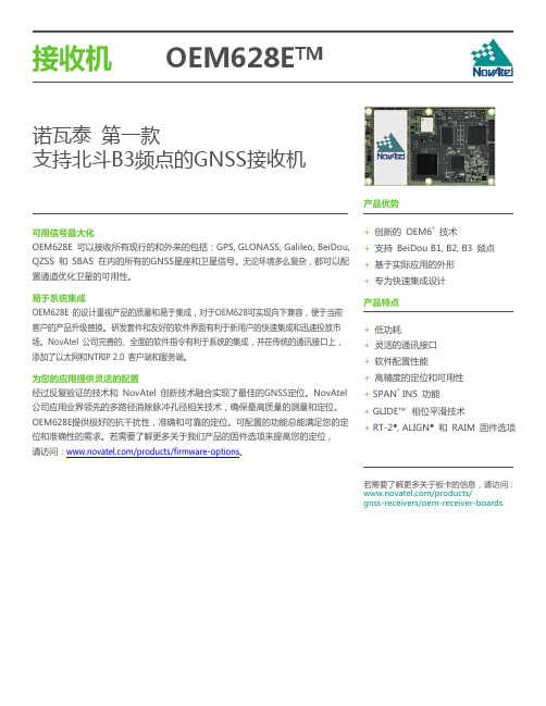
OEM617D板卡上海北寻信息科技OEM617D是Novatel推出,兼容BDS的多频测向板卡,支持双路天线信号输入,实现单板卡高精度定位定向,体积小重量轻,适合于集成开发。
跟踪信号GPSL1,L2,L2CGLONASSL1,L2GalileoE1BeiDouB1,B2SBASQZSS定位精度(RMS)单点L1 1.5m单点L1/L2 1.2mSBAS0.6mDGPS0.4mRTK1cm+1ppm定向精度2 m0.08 deg4 m0.05 deg初始化时间<10s初始化可靠性>99.9%定位数据更新率20Hz测向数据20Hz首次定位时间冷启动<50s典型热启动<35s典型信号重捕获L1<0.5s(典型)L2<1.0s(典型)速度精度0.03m/sRMS时间精度20nsRMS测量精度(RMS)GPS GLOL1C/A码4cm 8cmL1载波相位0.5mm 1.0mmL2P(Y)码8cm 8cmL2载波相位 1.0mm 1.0mmL2C码8cm 8cmL2C载波相位0.5mm 0.5mmL5码3cmL5载波相位0.5mm尺寸46mm×71mm×11mm 电源 3.3V±5%天线接口馈电5V通讯接口LVTTL3USB2.0Device1CAN总线2环境指标随机振动MIL-STD810G(7.7gRMS)正弦振动IEC60068-2-6(5g)工作冲击MIL-STD810G(40g)非工作冲击MIL-STD810G(75g)工作温度-40°C~+85°C存储温度-40°C~+95°C湿度95%无冷凝。
BDCCA 4.52.461.800 3.600R.0212 PLCS.2056PLCS2.122.00±.02.066 PLCSFULL RAD 6 PLCSR.134 PLCSAASEE NOTE 4.188.188.007SEE DETAILSECTION A-ANOTES:1. MATERIAL: MAKE FROM HENKEL AL-2-45H-212.2. THICKNESS: .007±.001.3. SEE DETAIL FOR ASSY ORDER.4. FOR ARTWORK SHOWN HERE SEE DWG# 20200.5. DENOTE CRITICAL CHARACTERISTIC FOR LOT INSPECTION.6. RoHS COMPLIANT PER CST-0001 LATEST REVISION.7. PRIOR TO ASSEMBLY, PRODUCTS SHALL BE STORED IN A COOL, DRY LOCATION IN ORIGINAL PACKAGING AT TEMPERATURES BELOW 40°C (104°F). UNDER THESE CONDITIONS THE SHELF LIFE IS INDEFINITE. THERMMATE PADS CAN BE PRE-APPLIED TO BASEPLATES OR HEAT SINKS WHICH ARE THEN SHIPPED TO A FINAL ASSEMBLY LOCATION, AS LONG AS THE TEMPERATURE DOES NOT EXCEED THE LEVEL INDICATED ABOVE.FEDETAIL :A. SPLIT RELEASE LINER.B. ADHESIVE STRIP; .0025 THICK .188 WIDE.C. ALUMINUM ALLOY 1145-0; .002 THICK.D. ROLL CARRIER WITH ADHESIVE STRIP BONDING.E. PHASE CHANGE THERMAL COMPOUND.F. ADHESIVE STRIPS ON ROLL CARRIER.(VERTICAL THICKNESS IS NOT SHOWN TO SCALE).188.007PEI AABBCCDDEEFF1122334455667788SWDTHERMAL INTERFACE PADTHERMATE (MAXI)P/N 202632/13/97J. RENAUDDATE DRAWN REV5DWG NO16188CAGE CODE67131SIZEBSHEET 1 OF 1SCALE 1: 1RELEASED PER E0430434VICORUNLESS OTHERWISE SPECIFIED DIMENSIONS ARE INCH [MM]TOLERANCES ARE:DECIMALS ANGLES X.XX [X.X] = ±0.01 [0.25] ±1°X.XXX [X.XX] = ±0.005 [0.127]FN 2REVISED PER E101310b KUK 09/16/04REVISED PER E090673C REVISED PER E091595a AR JS 3404/22/0909/10/09REJH REJH DO NOT SCALE DRAWINGTHIRD ANGLE PROJECTIONVICOR CONFIDENTIALTHIS DOCUMENT AND THE DATA DISCLOSED HEREIN OR HEREWITH IS NOT TO BE REPRODUCED, USED ORDISCLOSED IN WHOLE OR IN PART TO ANYONE WITHOUT THE PERMISSION OF VICOR CORP.DATE 1DESCRIPTIONFINISHREVISIONSREV MATERIALAPPROVED10/22/10AR 11/07/11KUKREVISED PER E1110905REJH/分销商库存信息: VICOR20263。
Trimble® BD970 GNSS 系统是一款紧凑型的多星接收机,专为满足各种精确到厘米级的定位精度应用需求而设计。
•220 个通道:– GPS:同步L1 C/A、L2E、L2C、L5– GLONASS:同步L1 C/A、L1 P、L2 C/A (仅限于GLONASS M)和L2 P– SBAS:同步L1 C/A、L5– GIOVE-A:同步L1 BOC、E5A、E5B 和E5AltBOC1– GIOVE-B:同步L1 CBOC、E5A、E5B 和E5AltBOC1– GALILEO:未开通2•天宝Maxwell 6 高级民用测量GNSS 技术•用于全球导航卫星系统伪距测量的高精度多相关器•未经滤波、未平滑的伪距测量数据,用于低噪音、低多路径误差、低时域相关性和高动态响应•噪音极低的GNSS 载波相位测量,1 赫兹带宽内的精度<1 毫米•dB-Hz 内报告的信噪比•应用成熟的天宝低仰角跟踪技术初始化时间3 通常<10 秒初始化可靠性3 >99.9%•一个USB 端口•一个CAN 端口•一个LAN 以太网端口:–支持链接10BaseT/100BaseT 网络–通过单一IP 地址执行全部功能同步性——包括网页图形用户界面访问和原始数据流–支持网络协议HTTP(网页图形用户界面)NTP 服务器基于TCP/IP 的NMEA、GSOF、CMR 等或者UDPNTripCaster、NTripServer、NTripClientmDNS/uPnP 服务搜寻动态DNS电子邮件警报谷歌地球网络链接支持基于PPP 的外置调制解调器• 3 x RS232 端口–波特率高达115,200• 1 Hz、2 Hz、5 Hz、10 Hz、20 和50 Hz 定位输出(取决于安装选项)•高达50 赫兹的原始测量与定位输出参考输出. . . . . . . . . . CMR、CMR+、RTCM 2.1、2.2、2.3、3.0、3.1导航输出. . . . . . . . . .ASCII: NMEA-0183 GSV、AVR、RMC、HDT、VGK、VHD、ROT、GGK、GGA、GSA、ZDA、VTG、GST、PJT、PJK、BPQ、GLL、GRS、GBS 以及二进制:TrimbleGSOF•控制软件– HTML 网页浏览器:Internet Explorer 7.0 或更高版本– Firefox 3.5 或更高版本– Safari 4.0– Opera 9– Google Chrome•每秒1 脉冲输出•事件标记输入支持LED 驱动支持. . . . . . . . . . . .(显示电源、卫星跟踪和差分数据)定位规格模式精度延迟时间最大速率同步RTK 1 cm + 1 ppm 水平2 cm + 1 ppm 垂直300 ms10 Hz低延时RTK 2 cm + 2 ppm 水平3 cm + 2 ppm 垂直<20 ms50 HzDGPS<1 m 3D<20 ms50 Hz SBAS8<5 m 3D<20 ms50 Hz物理特性尺寸. . . . . . . . . . . . . . . . . 100 mm X 60 mm X 11.6 mm电源. . . . . . . . . . . . . . . . . 3.3V DC +5%/-3%,典型1.4W (L1/L2 GPS)典型1.5W (L1/L2 GPS 和G1/G2 GLONASS)重量. . . . . . . . . . . . . . . . .62 克连接器I/O . . . . . . . . . . . . . . . . . . 24 排针转接口+6 排针转接口天线. . . . . . . . . . . . . . . . . .MMCX 插座环境特征温度工作温度. . . . . . . . . . . . . . . . –40 °C 至+75 °C储存温度. . . . . . . . . . . . . . . . .–55 °C 至+85 °C振动. . . . . . . . . . . . . . . . . . .定制:MIL810F,运行:随机6.2 gRMS限值:随机8 gRMS机械冲. . . . . . . . . . . . . . . . . MIL810D运行:±40 g限值:±75 g。
5.1 5.0 4.02012-06-272012-05-022009-06-30SStSStRStSStCZWürth Elektronik eiSos GmbH & Co. KGEMC & Inductive SolutionsMax-Eyth-Str. 174638 WaldenburgGermanyTel. +49 (0) 79 42 945 - 0A Dimensions: [mm]F Typical Impedance Characteristics:H4: Classification Wave Soldering Profile:H5: Classification Wave ProfileProfile FeaturePreheat- Temperature Min (T smin )- Temperature Typical (T stypical ) - Temperature Max (T smax ) - Time (t s ) from (T smin to T smax )Δ preheat to max Temperature Peak temperature (T p )Time of actual peak temperature (t p )Ramp-down rate - Min - Typical - MaxTime 25°C to 25°C Pb-Free Assembly 100°C 120°C 130°C 70 seconds 150°C max.250°C - 260°C max. 10 secondsmax. 5 second each wave ~ 2 K/s ~ 3.5 K/s ~ 5 K/s 4 minutesSn-Pb Assembly 100°C 120°C 130°C 70 seconds 150°C max.235°C - 260°C max. 10 secondsmax. 5 second each wave ~ 2 K/s ~ 3.5 K/s ~ 5 K/s 4 minutesrefer to EN 61760-1:2006H Soldering Specifications:I Cautions and Warnings:The following conditions apply to all goods within the product series of WE-SDof Würth Elektronik eiSos GmbH & Co. KG:General:All recommendations according to the general technical specifications of the data-sheet have to be complied with.The disposal and operation of the product within ambient conditions which probably alloy or harm the wire isolation has to be avoided.If the product is potted in customer applications, the potting material might shrink during and after hardening. Accordingly to this the product is exposed to the pressure of the potting material with the effect that the core, wire and termination is possibly damaged by this pressure and so the electrical as well as the mechanical characteristics are endanger to be affected. After the potting material is cured, the core, wire and termination of the product have to be checked if any reduced electrical or mechanical functions or destructions have occurred.The responsibility for the applicability of customer specific products and use in a particular customer design is always within the authority of the customer. All technical specifications for standard products do also apply for customer specific products.Washing varnish agent that is used during the production to clean the application might damage or change the characteristics of the wire in-sulation, the marking or the plating. The washing varnish agent could have a negative effect on the long turn function of the product.Direct mechanical impact to the product shall be prevented as the ferrite material of the core could flake or in the worst case it could break. Product specific:Follow all instructions mentioned in the datasheet, especially:•The solder profile has to be complied with according to the technical wave soldering specification, otherwise no warranty will be sustai-ned.•All products are supposed to be used before the end of the period of 12 months based on the product date-code, if not a 100% solderabi-lity can´t be warranted.•Violation of the technical product specifications such as exceeding the nominal rated current will result in the loss of warranty.1. General Customer ResponsibilitySome goods within the product range of Würth Elektronik eiSos GmbH & Co. KG contain statements regarding general suitability for certain application areas. These statements about suitability are based on our knowledge and experience of typical requirements concerning the are-as, serve as general guidance and cannot be estimated as binding statements about the suitability for a customer application. The responsibi-lity for the applicability and use in a particular customer design is always solely within the authority of the customer. Due to this fact it is up to the customer to evaluate, where appropriate to investigate and decide whether the device with the specific product characteristics described in the product specification is valid and suitable for the respective customer application or not.2. Customer Responsibility related to Specific, in particular Safety-Relevant ApplicationsIt has to be clearly pointed out that the possibility of a malfunction of electronic components or failure before the end of the usual lifetime can-not be completely eliminated in the current state of the art, even if the products are operated within the range of the specifications.In certain customer applications requiring a very high level of safety and especially in customer applications in which the malfunction or failure of an electronic component could endanger human life or health it must be ensured by most advanced technological aid of suitable design of the customer application that no injury or damage is caused to third parties in the event of malfunction or failure of an electronic component.3. Best Care and AttentionAny product-specific notes, warnings and cautions must be strictly observed.4. Customer Support for Product SpecificationsSome products within the product range may contain substances which are subject to restrictions in certain jurisdictions in order to serve spe-cific technical requirements. Necessary information is available on request. In this case the field sales engineer or the internal sales person in charge should be contacted who will be happy to support in this matter.5. Product R&DDue to constant product improvement product specifications may change from time to time. As a standard reporting procedure of the Product Change Notification (PCN) according to the JEDEC-Standard inform about minor and major changes. In case of further queries regarding the PCN, the field sales engineer or the internal sales person in charge should be contacted. The basic responsibility of the customer as per Secti-on 1 and 2 remains unaffected.6. Product Life CycleDue to technical progress and economical evaluation we also reserve the right to discontinue production and delivery of products. As a stan-dard reporting procedure of the Product Termination Notification (PTN) according to the JEDEC-Standard we will inform at an early stage about inevitable product discontinuance. According to this we cannot guarantee that all products within our product range will always be available. Therefore it needs to be verified with the field sales engineer or the internal sales person in charge about the current product availability ex-pectancy before or when the product for application design-in disposal is considered.The approach named above does not apply in the case of individual agreements deviating from the foregoing for customer-specific products.7. Property RightsAll the rights for contractual products produced by Würth Elektronik eiSos GmbH & Co. KG on the basis of ideas, development contracts as well as models or templates that are subject to copyright, patent or commercial protection supplied to the customer will remain with Würth Elektronik eiSos GmbH & Co. KG.8. General Terms and ConditionsUnless otherwise agreed in individual contracts, all orders are subject to the current version of the “General Terms and Conditions of Würth Elektronik eiSos Group”, last version available at .J Important Notes:The following conditions apply to all goods within the product range of Würth Elektronik eiSos GmbH & Co. KG:分销商库存信息: WURTH-ELECTRONICS 744710215。