ABB EL3060 Datasheet 中文
- 格式:pdf
- 大小:5.90 MB
- 文档页数:16

00813-0100-4733, Rev KA Catalog 2006 - 2007Rosemount 305 and 306 ManifoldsROSEMOUNT 305 AND 306 FEATURE...•Unique Coplanar ™ design of the Rosemount 3051 and 3095 families allows “flangeless” valve integration•Coplanar, traditional, and inline styles •Compact, lightweight assembly •Factory assembled, seal-tested and calibrated•Easy in-process calibration•50% fewer possible leak points thanconventional manifold/transmitter assemblies •Direct-mount capabilityContentsSpecifications . . . . . . . . . . . . . . . . . . . . . . . . . . . . . . . . . . . . . . . . . . . . . . . . . . . . . .page 4Dimensional Drawings. . . . . . . . . . . . . . . . . . . . . . . . . . . . . . . . . . . . . . . . . . . . . . . .page 7Ordering Information . . . . . . . . . . . . . . . . . . . . . . . . . . . . . . . . . . . . . . . . . . . . . . . .page 13Rosemount 305 and 306 Integral Manifolds00813-0100-4733, Rev KACatalog 2006 - 2007Rosemount 305 and 306 Manifolds2Rosemount 305R Coplanar Style Integral Manifolds305R TWO-VALVEThis two-valve manifold is used with Rosemount 3051 gage and absolute pressure transmitters. The first valve provides instrument isolation. The second valve allows venting, draining, or calibration through the test port.•305RC2 •305RT2•305RM2•305RC7305R THREE-VALVEThis three-valve manifold is used with Rosemount 3095 and 3051 differential pressure transmitters. It provides two blocking valves and one equalizing valve. Two drain/vent valves are also installed at the test ports.•305RC3•305RT3•305RM3•305RC8ROSEMOUNT 305R FIVE-VALVEThis five-valve manifold is used with 3095 and 3051 differential pressure transmitters. It provides two blocking valves, two test/vent valves, and oneequalizing valve. The two vent valves allow for 100% capture of vented or drained process, and simplified in-process calibration capability. We also offer a five-valve integral manifold with a metering pattern for Natural Gas installations.•305RC5•305RC6•305RC9•305RM5NOTEStandard two-valve and standard 5-valve manifold Test/Vents receive plastic caps to protect threaded connections.NOTEFive-valve Natural Gas Test (Plugged) connections receive 1/4-in. NPT plug.Coplanar TransmitterVent ValveCoplanar TransmitterTest \ Vent PortFIVE-VALVE NATURAL GASCoplanar TransmitterTest (Plugged)Test(Plugged)00813-0100-4733, Rev KA Catalog 2006 - 20073Rosemount 305 and 306 Manifolds306RT TWO-VALVE MANIFOLDSThis two-valve pressure manifold is used with 3051 and 2088 gage and absolute pressure transmitters. The first valve provides instrument isolation. The second valve allows venting, draining, or calibration through the test port. Available in 1/2–14 NPT male or female process connections.•306RT2306RT BLOCK-AND-BLEED MANIFOLDSThis pressure manifold is used with 3051 and 2088 gage and absolute pressure transmitters. It provides a single block valve for instrument isolation. There is also a plug for drain/vent capabilities. Available in 1/2–14 NPT male process connection.•306RT1Pressure TransmitterBleed ScrewPressure Transmitter00813-0100-4733, Rev KACatalog 2006 - 2007 Rosemount 305 and 306 Manifolds4SpecificationsFIGURE 1. 305R integral Manifolds - Pressure vs. Temperature(-18)(38)(149)(204)(260)(316)(371)(427)(538)Temperature °F (°C)Pressurepsig(bar)(93)(482)6092TABLE 1. 305R Integral manifolds - pressure and temperature ratings(1)Seat Pressure and Temperature Ratings PTFE Integral6092 psi @ 200°F (420 bar @ 93°C)4000 psi @ 400°F (276 bar @ 204°C) Graphite Integral6092 psi @ 200°F (420 bar @ 93°C)1500 psi @ 750°F (103 bar @ 399°C) Graphite (ASME B31.1)Integral6092 psi @ 100°F (420 bar @ 38°C)2915 psi @ 1000°F (201 bar @ 538°C) (1)Except option HK:PTFE, Integral seat: 2324 psi @ 200°F (160 bar @ 93°C), 1680 psi @ 400°F (116 bar @ 204°C)Graphite, Integral seat: 2324 psi @ 200°F (160 bar @ 93°C), 1125 psi @ 750°F (78 bar @ 399°C)00813-0100-4733, Rev KA Catalog 2006 - 20075Rosemount 305 and 306 ManifoldsFIGURE 2. 306R integral Manifolds - Pressure vs. Temperature10000(689)8000600040002000(-18)(38)(149)(204)(260)(316)(371)(427)(538)Temperature °F (°C)P r e s s u r e p s i g (b a r )(93)(482) TABLE 2. 306R Integral manifolds - pressure and temperature ratingsSeat Pressure and Temperature Ratings PTFE Integral 10000 psi @ 85°F (689 bar @ 29°C)4000 psi @ 400°F (276 bar @ 204°C)GraphiteIntegral 6000 psi @ 200°F (414 bar @ 93°C)1500 psi @ 750°F (103 bar @ 399°C)Graphite (ASME B31.1)Integral6000 psi @ 100°F (414 bar @ 38°C)2915 psi @ 1000°F (201 bar @ 538°C)TABLE 3. Process Wetted Materials of Construction - Typical (1)316SSTHastelloy C Monel316 SST with SG option Body (2)316 SSTHastelloy C-276Monel 400316 SSTBall / Tip 316 SST /316Ti SST Hastelloy C-276Monel 400 / K500Hastelloy C-276Stem 316 SSTHastelloy C-276Monel 400 / R-405Hastelloy C-276Packing PTFE / Graphite PTFE / Graphite PTFE / Graphite PTFE / Graphite Bonnet 316 SST Hastelloy C-276Monel 400 / R-405316 SST Pipe Plug 316 SSTHastelloy C-276Monel 400 / R-405316 SSTBleed Screw316 SST / 316Ti SST Hastelloy C-276Monel 400 / R-405 / K500Hastelloy C-276Drain / Vent Valve316 SSTHastelloy C-276Monel 400Hastelloy C-276(1)Non-wetted parts are 300 series SST.(2)Body may be supplied as appropriate cast equivalent.00813-0100-4733, Rev KACatalog 2006 - 2007 Rosemount 305 and 306 Manifolds6Shipping WeightsTest Connections1/4-18 NPTAdaptersDF option, CF-8M (Cast version of 316 SST, materialper ASTM-A743)Bolts for ManifoldsStandard material is plated carbon steel per ASTM A449, Type 1Alternative bolt materials offered through Option Codes•L4 Austenitic 316 Stainless Steel Bolts•L5 ASTM-A-193, Grade B7M Bolts•L8 ASTM-A-193, Class 2, Grade B8M BoltsISOLATION VALVENote: “Typical” ValveTABLE 4. 305 Manifold Weights Without Options, lb (kg)ModelApproximateManifoldWeightManifoldwith3051CManifold3051S_C (1)(1)3051S Module only; see Rosemount product data sheet00813-0100-4801 for additional information.Manifoldwith 30950305_C2 4.5 (2,0)9.4 (4,3)7.6 (3,4) 9.9 (4,5)0305_C3 4.7 (2,1)9.6 (4,4)7.8 (3,5)10.1 (4,6)0305_C5 6.5 (3,0)11.4 (5,17)9.6 (4,4)11.9 (5,4)0305_C6 6.4 (2,9)11.3 (5,1)9.5 (4,3)11.8 (5,35)0305_C7 4.7 (2,1)9.6 (4,4)7.8 (3,5)10.1 (4,6)0305_C8 5.0 (2,3)9.9 (4,5)8.1 (3,7)10.4 (4,8)0305_C9 6.3(2,85)11.2 (5,1)9.4 (4,25)11.7 (5,3)0305_T2 6.0 (2,7)10.9 (4,9)9.1 (4,1)–0305_T3 6.0 (2,7)10.9 (4,9)9.1 (4,1)–0305_T7 6.2 (2,8)11.1 (5,0)9.3 (4,2)–0305_T8 6.2 (2,8)11.1 (5,0)9.3 (4,2)–TABLE 5. 306 Manifold Weights Without Options, lb (kg)ModelApproximatelyManifoldWeightManifoldwith 3051TManifold3051S_T(1)(1)3051S Module only; see Rosemount product data sheet00813-0100-4801 for additional information.Manifoldwith 20880306_T1 1.1 (0,5) 4.1 (1,9) 2.5 (1,1) 3.1 (1,4)0306_T2 2.5 (1,1) 5.5 (2,5) 3.9 (1,7) 4.5 (2,0)0306_T3 2.5 (1,1) 5.5 (2,5) 3.9 (1,7) 4.5 (2,0)00813-0100-4733, Rev KA Catalog 2006 - 20077Rosemount 305 and 306 ManifoldsDimensional Drawings00813-0100-4733, Rev KACatalog 2006 - 2007Rosemount 305 and 306 Manifolds800813-0100-4733, Rev KA Catalog 2006 - 20079Rosemount 305 and 306 Manifolds00813-0100-4733, Rev KACatalog 2006 - 2007Rosemount 305 and 306 Manifolds101112Ordering InformationTABLE 6. Rosemount 305R Integral Manifolds0305Integral ManifoldR Rosemount Inc.C CoplanarT TraditionalM Traditional (Rosemount 3095-compatible; DIN-compliant flange)22-valve33-valve5(1)5-valve6(2)5-valve for natural gas/metering pattern7(2)(3)2-valve (per ASME B31.1[ANSI] power and piping code)8(2)(3)3-valve (per ASME B31.1[ANSI] power and piping code)9(2)(3)5-valve (per ASME B31.1[ANSI] power and piping code)2316 SST316 SST316 SST316 SST3(4)(5)Hastelloy® C Hastelloy C Hastelloy C Hastelloy C4(4)Monel®Monel Monel MonelA¼–18 NPT (Traditional manifold styles T and M)B1/2–14 NPT (Coplanar manifold style only)1Teflon2(6)Graphite-based1 Integral5Soft delrin (only available with natural gas/ metering pattern)13TABLE 6. Rosemount 305R Integral ManifoldsP2Cleaning for special services (Not available with graphite-based packing)SG(5)(7)316 SST NACE option (316 SST body and bonnet; Hastelloy C drain/vent, stem and tip/ball) for H2S ServiceL4(8)Austenitic 316 SST boltsL5ASTM-A-193-B7M boltsL8ASTM-A-193, Class 2, Grade B8M boltsCoplanar OptionsB4SST bracket for 2-in. pipe mount with series 300 SST boltsTraditional OptionsB1Bracket for 2-in. pipe mounting, CS boltsB3(9)Flat bracket for 2-in. pipe mounting, CS boltsB7B1 bracket with series 300 SST boltsB9(9)B3 bracket with series 300 SST boltsBA SST B1 bracket with series 300 SST boltsBC(9)SST B3 bracket with series 300 SST boltsBD SST Bracket with Series 300 SST Bolts for 305RM5 ManifoldsDF1/2–14 NPT flange adapters, Material of construction; match body material and packing material(Not available with graphite-based packing or HK, HL options)HK(10)10mm (M10) process flange bolting connectionHL(10)12mm (M12) process flange bolting connection(1)Not available with traditional manifold style T.(2)Only available with Coplanar manifold style(3)Only available with 316SST materials of construction and graphite-based packing.(4)Not available with traditional manifold Style M.(5)Materials of Construction comply with recommendations per NACE MR 0175/ISO 15156 for sour oil field production environments. Environmental limitsapply to certain materials. Consult latest standard for details. Selected materials also conform to NACE MR0103 for sour refining environments.(6)Includes graphite tape on drain/vent valves and plugs.(7)Only available with Materials of Construction Code 2: 316 SST body and bonnets; Hastelloy C stems, tip/balls, and drain/vents.(8)Not available with manifold codes 7, 8, and 9.(9)Not compatible with the Rosemount 3095 transmitter.(10)Only available with traditional manifold style M.14TABLE 7. Rosemount 306RT Integral Manifolds0306Pressure ManifoldR Rosemount Inc.T Threaded1Block-and-bleed22-valve3(1)2-valve (per ASME B31.1 [ANSI] power and piping code)2316 SST316 SST316 SST316 SST3(2)(3)Hastelloy C Hastelloy C Hastelloy C Hastelloy CAA1/2–14 male NPTBA(2)1/2–14 female NPT1Teflon2(4)Graphite-based1IntegralP2Cleaning for special services (Not available with graphite-based packing)SG(3)(5)316 SST NACE option (316 SST body and bonnet; Hastelloy C stem and tip/ball). For H2S Service3062211(1)Only available with 316SST materials of construction and graphite-based packing.(2)Not available with block-and-bleed manifold type(3)Materials of Construction comply with recommendations per NACE MR0175/ISO 15156 for sour oil field production environments. Environmental limitsapply to certain materials. Consult latest standard for details. Selected materials also conform to NACE MR0103 for sour refining environments.(4)Includes graphite tape on plugs.(5)Only available with material of construction code 2.15Emerson Process Management© 2006 Rosemount Inc. All rights reserved.¢00813-0100-4733w¤Rosemount and the Rosemount logotype are registered trademarks of Rosemount Inc.Coplanar is a trademark of Rosemount Inc.Monel is a registered trademark of International Nickel Co.Hastelloy is a registered trademark of Haynes InternationalTeflon is a registered trademark of E.I. du Pont de Nemours & Co.Emerson Process Management Heath Place Bognor Regis West Sussex PO22 9SH England T 44 (0) 1243 863121F 44 (0) 1243 867554Emerson Process Management Asia Pacific Private Limited 1 Pandan Crescent Singapore 128461T (65) 6777 8211F (65) 6777 0947Enquiries@AP Rosemount Inc.8200 Market BoulevardChanhassen, MN 55317 USA T(U.S.)180****9307T (International) (952) 906 8888F (952) 949 OPTIONS Module GuardA sensor module guard is available to protect the transmitter process isolating diaphragms. This guard should be used whenever the transmitter is removed from the integral manifold to avoid damage to the isolating diaphragms.•Part number: 00305-1000-0001 (5/pack)P2 Cleaning for Special ServicesThis option minimizes process contaminants by cleaning wetted surfaces with a suitable detergent.SG Sour GasMaterials of Construction comply withrecommendations per NACE MR 0175/ISO 15156 for sour oil field production environments. Environmental limits apply to certain materials. Consult lateststandard for details. Selected materials also conform to NACE MR0103 for sour refining environments.ASME B31.1 (ANSI)The 305 and 306 Manifolds are available inconfigurations that meet the requirements of ASME B31.1(ANSI) Power and Piping Code. This code specifies design criteria for most air, gas, steam, water, and oil systems used in electric generating systems, central and district heating systems,industrial power plants and geothermal plants. ASME B31.1(ANSI) includes requirements for manifolds, valves, and piping. Transmitters and other measuring devices do not fall within the scope of this code.MarkingManifolds are tagged with a part number, schematic drawing, temperature and pressure limits.Other PublicationsFor additional information, go to.3051-3031C 07F。

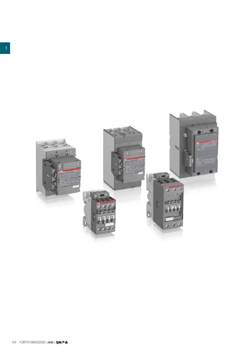
11/0 1SXF101060C2002 |ABB|控制产品1概览1/2订货信息4 - 45 kW / 5 - 60 hpAF09 ... AF38 交/直流操作1/5AF09Z ... AF38Z 交/直流操作,低功耗1/6AF40 ... AF96 交/直流操作1/7主要附件1/855 - 200 kW / 75 - 300 hpAF116 ... AF146 交/直流操作,带1NO + 1NC辅助触点1/10AF190 ... AF370 交/直流操作,带1NO + 1NC辅助触点1/11主要附件1/12 200 - 560 kW / 300 - 900 hpAF400 ... AF750 交/直流操作,带1NO + 1NC辅助触点1/14AF1250 ... AF2650 交/直流操作,带1NO + 1NC辅助触点1/15主要附件1/16技术数据1/18端子标识和位置1/31主要尺寸1/34ABB|控制产品| 1SXF101060C2002 1/11用于控制电动机及电力线路IEC (1)AC-3 额定功率θ ≤ 60 °C (2), 400 V kW4 5.57.5111518.518.522303745UL/CSA 3 相电动机480 V hp57.5101520203040506060交/直流控制电压型号AF09AF12AF16AF26AF30AF38AF40AF52AF65AF80AF96IEC AC-3 额定工作电流θ ≤ 60 °C (2), 400 V A912182632384053658096 AC-1 额定工作电流θ ≤ 40 °C, 690 V A25283045505070100105125130UL/CSA一般应用的额定电流600 V A252830455050608090105115 NEMA NEMA 尺寸000—1——2——3—(1) 1000 V IEC额定参数,适用于AF146 ... AF2650接触器。
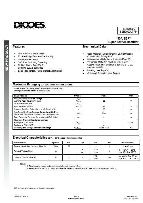
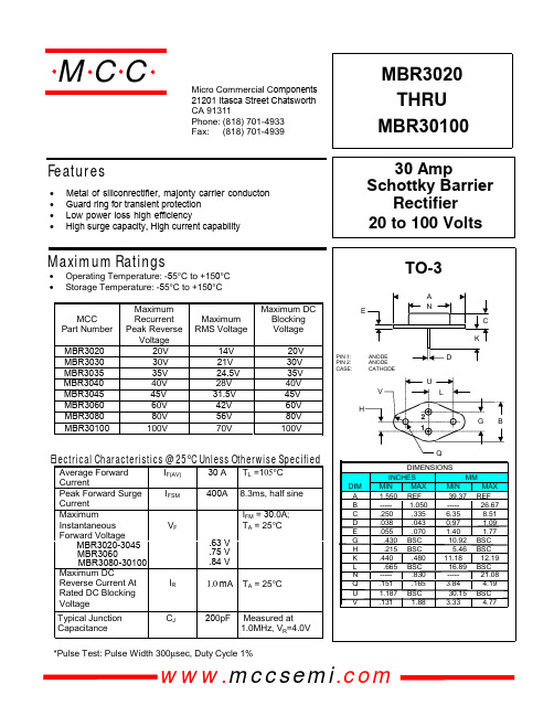
30A SBR®Super Barrier RectifierFeatures MechanicalData• Case Material: Molded Plastic, UL FlammabilityClassification Rating 94V-0• Moisture Sensitivity: Level 1 per J-STD-020C• Terminals: Matte Tin Finish annealed overCopper leadframe. Solderable per MIL-STD-202,Method 208• Marking: See Page 3• Ordering Information: See Page 3• Low Forward Voltage Drop• Excellent High Temperature Stability• Super Barrier Design• Soft, Fast Switching Capability• Molded Plastic TO-220AB,and ITO-220AB packages• Lead Free Finish, RoHS Compliant (Note 2)Maximum Ratings @ T A = 25ºC unless otherwise specifiedSingle phase, half wave, 60Hz, resistive or inductive load.For capacitive load, derate current by 20%.Characteristic SymbolValueUnit Peak Repetitive Reverse VoltageWorking Peak Reverse VoltageDC Blocking VoltageV RRMV RWMV RM60 VRMS Reverse Voltage V R(RMS)42 VAverage Rectified Output Current @ T C = 110ºC I O30 ANon-Repetitive Peak Forward Surge Current 8.3msSingle Half Sine-Wave Superimposed on Rated LoadI FSM200 APeak Repetitive Reverse Surge Current (2uS-1Khz) I RRM 2 AMaximum Thermal Resistance (per leg)Package = TO-220ABPackage = ITO-220ABRӨJC 24°C/WOperating and Storage Temperature Range T J, T STG-65 to +150 ºCElectrical Characteristics @ T A = 25ºC unless otherwise specifiedCharacteristic SymbolMin Typ Max Unit Test ConditionReverse Breakdown Voltage (Note 1) V(BR)R60 - - V I R = 0.5 mAForward Voltage Drop V F--0.620.700.65VI F = 15A, T J = 25ºCI F = 15A,T J = 125ºCLeakage Current (Note 1) I R- -0.5100mAV R = 60V, T J= 25 ºCV R = 60V, T J = 125 ºCNotes:1. Short duration pulse test used to minimize self-heating effect.2. RoHS revision 13.2.2003. High temperature solder exemption applied, see EU Directive Annex Note 7.__________SBR is a registered trademark of Diodes Incorporated.Package Outline DrawingsTO-220AB ITO-220ABTO-220ABDIM. MIN. MAX.A 4.47 4.67b 0.71 0.91b1 1.17 1.37c 0.31 0.53D 14.65 15.35D1 8.50 8.90E 10.01 10.31e 2.54type1 4.98 5.18F 1.17 1.37J1 2.52 2.82L 13.40 13.80L1 3.56 3.96ØP 3.735 3.935Q 2.59 2.89All Dimensions in MillimetersITO-220ABDIM. MIN. MAX.A 4.30 4.70b 0.50 0.75b1 1.10 1.35b2 1.50 1.75c 0.50 0.75D 14.80 15.20E 9.96 10.36e 2.54typF 2.80 3.20J1 2.50 2.90L 12.80 13.60L1 1.70 1.90ØP 3.50typQ 2.70typAll Dimensions in MillimetersMarking, Polarity, Weight & Ordering InformationSBR3060CT SBR3060CTFP Case StyleTO-220AB ITO-220ABtAnodeCommonCathode AnodePolarityCasetAnodeCommonCathode AnodeMarking2.1g 1.9gWeightOrderingInformationSBR3060CT SBR3060CTFP50 pieces/tube50 pieces/tubeYY = Last two digits of year, ex = 06 = 2006Date CodeWW = Week (01-52)Other MarkingInformationA = Foundry CodeB = Assembly CodeIMPORTANT NOTICEDiodes Incorporated and its subsidiaries reserve the right to make modifications, enhancements, improvements, corrections or other changeswithout further notice to any product herein. Diodes Incorporated does not assume any liability arising out of the application or use of any productdescribed herein; neither does it convey any license under its patent rights, nor the rights of others. The user of products in such applications shallassume all risks of such use and will agree to hold Diodes Incorporated and all the companies whose products are represented on our website,harmless against all damages.LIFE SUPPORTDiodes Incorporated products are not authorized for use as critical components in life support devices or systems without the expressed writtenapproval of the President of Diodes Incorporated.。
AMIS-30624I2C Micro-stepping Motor Driver 1.0General DescriptionThe AMIS-30624 is a single-chip micro-stepping motor driver with a position controller and control/diagnostic interface. It is ready to build intelligent peripheral systems where up to 32 drivers can be connected to one I2C master. This significantly reduces system complexity.The chip receives positioning instructions through the bus and subsequently drives the stator coils so the two-phase stepper motor moves to the desired position. The on-chip position controller is configurable (OTP or RAM) for different motor types, positioning ranges and parameters for speed, acceleration and deceleration. Micro-stepping allows silent motor operation and increased positioning resolution. The advanced motion qualification mode enables verification of the complete mechanical system in function of the selected motion parameters. The AMIS-30624 can easily be connected to an I2C bus where the I2C master can fetch specific status information like actual position, error flags, etc. from each individual slave node.An integrated sensorless stall detection stops the motor when running into stall. This enables silent, yet accurate position calibrations during a referencing run and allows semi-closed loop operation when approaching the mechanical end-stops.The chip is implemented in I2T100 technology, enabling both high voltage analog circuitry and digital functionality on the same chip. The AMIS-30624 is fully compatible with the automotive voltage requirements.2.0Product FeaturesMotor Driver• Micro-stepping technology•Sensorless stall detection•Peak current up to 800mA•Fixed frequency PWM current-control•Selectable PWM frequency•Automatic selection of fast and slow decay mode•No external fly-back diodes required• 14V/24V compliant•Motion qualification modeController with RAM and OTP memory• Position controller•Configurable speeds and acceleration•Input to connect optional motion switchI2C interface• Bi-directional 2-wire bus for Inter IC Control•Field programmable node addresses•Full diagnostics and status informationProtection• Over-current protection• Under-voltage management•Open circuit detection•High-temp warning and management• Low-temp flagEMI compatibility•High voltage outputs with slope control•HV outputs with slope control3.0ApplicationsThe AMIS-30624 is ideally suited for small positioning applications. Target markets include: automotive (headlamp alignment, HVAC, idle control, cruise control), industrial equipment (lighting, fluid control, labeling, process control, XYZ tables, robots) and building automation (HVAC, surveillance, satellite dish, renewable energy systems). Suitable applications typically have multiple axes or require mechatronic solutions with the driver chip mounted directly on the motor.4.0Ordering InformationTable 1: Ordering InformationAMIS30624C6244G SOIC-20 Tube/Tray -40°C…..125°C 800mAAMIS30624C6244RG SOIC-20 Tape & Reel -40°C…..125°C 800mAAMIS30624C6245G NQFP-32 (7 x 7 mm) Tube/Tray -40°C…..125°C 800mAAMIS30624C6245RG NQFP-32 (7 x 7 mm) Tape & Reel -40°C…..125°C 800mA5.0Quick Reference DataTable 2: Absolute Maximum Ratings(1) Vvoltage -0.3 +40Vbb SupplyTamb Ambient temperature under bias (2) -50 +150 °CTst Storage temperature -55 +160 °CVesd (3) Electrostatic discharge voltage on pins -2 +2 kVNotes:(1) For limited time <0.5s(2) The circuit functionality is not guaranteed.(3) Human body model (100pF via 1.5 kΩ, according to JEDEC EIA-JESD22-A114-B)Table 3: Operating Rangesvoltage +8 +29 V Vbb SupplyVbb ≤ 18V -40 +125 °CTop Operating temperature rangeVbb ≤ 29V -40 +85 °C6.0Block Diagram7.0Pin OutTable 4: Pin DescriptionPin Name Pin Description SOIC-20 NQFP-32SDA I2C serial data line 1 8 SCK I2C serial clock line 2 9VDD Internal supply (needs external decoupling capacitor) 3 10GND Ground, heat sink 4,7,14,17 11, 14, 25, 26, 31, 32TST1 Test pin (to be tied to ground in normal operation) 5 12TST2 Test pin (to be left open in normal operation: internally pulled up) 6 13HW Hard wired address bit 8 15 CPN Negative connection of pump capacitor (charge pump) 9 17CPP Positive connection of pump capacitor (charge pump) 10 18VCP Charge-pump filter-capacitor 11 19VBB Battery voltage supply 12,19 3, 4, 5, 20, 21, 22MOTYN Negative end of phase Y coil 13 23, 2428 MOTYP Positive end of phase Y coil 15 27, MOTXN Negative end of phase X coil 16 29, 302 MOTXP Positive end of phase X coil 18 1, SWI Switch input 20 6NC Not connected (to be tied to ground) 7, 168.0Package Thermal Resistance8.1 SOIC-20To lower the junction-to-ambient thermal resistance, it is recommended to connect the ground leads to a printed circuit board (PCB) ground plane layout as illustrated in Figure 3. The junction-to-case thermal resistance is dependent on the copper area, copper thickness, PCB thickness and number of copper layers. Calculating with a total area of 460 mm2, 35µm copper thickness, 1.6mm PCB thickness and 1 layer, the thermal resistance is 28°C/W; leading to a junction-ambient thermal resistance of 63°C/W.9.0 DC ParametersThe DC parameters are given for Vbb and temperature in their operating ranges. Currents flowing in the circuit are defined as positive.Table 5: DC Parameters I MSmax,Peak Max. current through motor coilin normal operation800 mAI MSmax,RMS Max. RMS current through coil in normaloperation570 mAI MSabs Absolute error on coil current -10 10 %I MSrelError on current ratio I coilx / I coily-7 7 % V bb = 12V, T j = 50 °C 0.50 1 Ω V bb = 8V, T j = 50 °C 0.55 1 Ω V bb = 12V, T j = 150 °C 0.70 1 Ω R DSonOn resistance for each motor pin (including bond wire) at I MSmaxV bb = 8V, T j = 150 °C 0.85 1 Ω I MSLMOTXPMOTXN MOTYP MOTYNPull down currentHiZ mode2mAT tw Thermal warning138 145 152 °C T tsd (1) (2)Thermal shutdown T tw + 10 °C T low (2)Low temperature warningT tw - 155°C T amb ≤ 125 °C 6.5 18 V V bb Nominal operating supply rangeT amb ≤ 85 °C6.5 29 V V bbOTP Supply voltage for OTP zapping (3)9.0 10.0 VI bat Total current consumption Unloaded outputs 3.50 10.0 mA I bat_s Sleep mode current consumption 50 100 µA UV 1 Stop voltage high threshold 7.8 8.4 8.9 V UV 2 VBBStop voltage low threshold7.1 7.5 8.0 V V dd Internal regulated output (4)8V < V bb < 29V4.7555.50VI ddStop Digital current consumption V bb < UV 2 2 mA V ddReset Digital supply reset level @ power down(5)4.5 V I ddLim VDDCurrent limitation Pin shorted to ground 42 mA Rt_OFF Switch OFF resistance (6)10k Ω Rt_ON Switch ON resistance (6)Switch to Gnd or V bat ,2 k Ω V bb_sw Vbb range for guaranteed operation ofSWI and HW6 29 V V max_sw Maximum voltage T < 1s40V V I lim_swSWIHWCurrent limitationShort to Gnd or V bat 30mA2V IL Input level low (7)- 0.5 0.3 * V dd V V IH Input level high (8) 0.7 * V ddV dd + 0.5VV nL Noise margin at the LOW level for eachconnected device (including hysteresis)0.1 * V dd V V nHSDASCKNoise margin at the HIGH level for eachconnected device (including hysteresis)0.2 * V ddTable 5: DC Parameters (cont.) V bb > 15V V bb +10 V bb +12.5 V bb +15 V V cp Output voltage8V < V bb < 15V2 * V bb – 5 2 * V bb – 2.52 * V bb V C buffer VCPExternal buffer capacitor220 470 nF C pumpCPP CPN External pump capacitor220470nF V OUT Output voltage swing TestBemf I 2C command0 - 4,85 V R OUT Output impedance Service mode I 2C command2 k Ω Av SWI Gain = V SWI / V BEMFService mode I 2C command0,50Notes:(1) No more than 100 cumulated hours in life time above T tsd .(2) Thermal shutdown and a low temperature warning are derived from thermal warning. (3) A 10μF buffer capacitor of between VBB and GND is the minimum needed. Short connections to the power supply are recommended. (4) Pin VDD must not be used for any external supply(5) The RAM content will not be altered above this voltage.(6) External resistance value seen from pin SWI or HW, including 1k Ω series resistor.(7) If input voltages < - 0.3V, than a resistor between 22Ω to 100Ω needs to be put in series (8) If the I 2C-bus is operated in Fast Mode V IHmin = 0.7 * Vdd10.0 AC ParametersThe AC parameters are given for V bb and temperature in their operating ranges. All timing values of the I 2C transceiver are referred to V IHman and V ILmax levels (see Figure 5).Table 6: AC ParametersT puPower-up timeGuaranteed by design 10 ms f oscFrequency of internal oscillator 3.6 4.0 4.4 MHz 2C B Capacitive load of each bus line400 (1)pF C ICapacitance of SDA / SCK pin10pFt SPSDASCKPulse width of spikes which must besuppressed by the input filter50 ns2f SCL SCL clock frequency 100 kHz t HD,START Hold time (repeated) START condition. After this period the first clock pulse is generated.4.0 µs t LOW LOW period of the SCK clock4.7µst HIGH HIGH period of the SCK clock 4.0 µs t SU,START Set-up time for a repeated STARTcondition4.7 µst HD,DATA Data hold time for I 2C bus devices 0 (2) 3.45 (3)µs t SU,DATA Data set-up time250 ns t R Rise time of SDA and SCK signals 1.0 µs t F Fall time of SDA and SCK signals0.3 µs t SU,STOPSet-up time for STOP condition 4.0 µs t BUF SDA SCKBus free time between STOP andSTART condition4.7µs2f SCL SCL clock frequency 360 kHz t HD,START Hold time (repeated) START condition. After this period the first clock pulse is generated.0.6 µs t LOW LOW period of the SCK clock1.3µst HIGH HIGH period of the SCK clock 0.6 µs t SU,START Set-up time for a repeated STARTcondition0.6 µst HD,DATA Data hold time for I 2C bus devices 0 (2) 0.9 (3)µs t SU,DATA Data set-up time100 (4)ns t R Rise time of SDA and SCK signals 20 + 0.1C B 300 ns t F Fall time of SDA and SCK signals20 + 0.1C B300 ns t SU,STOP Set-up time for STOP condition 0.6 µs t BUFSDA SCKBus free time between STOP andSTART condition1.3µsTable 6: AC Parameters (cont.)T sw Scan pulse period (5)1024 µs T sw_on SWI HW2Scan pulse duration128µsµsPWMfreq = 0 (6) 20.6 22.8 25.0 kHz F pwm PWM frequency (5)PWMfreq = 1 (6)41,245,6 50,0 kHz F jit_depth PWM jitter modulation depth PWMJen = 1 (6)10 % T brise Turn-on transient time 170 ns T bfall Turn-off transient time Between 10% and 90% 140 ns T stab MOTxxRun current stabilization time293235msf CPCPN CPP Charge pump frequency (5)250 kHzNotes: (1)The maximum number of connected I 2C devices is dependent on the number of available addresses and the maximum bus capacitance to still guarantee the riseand fall times of the bus signals. (2) An I 2C device must internally provide a hold time of at least 300ns for the SDA signal (referred to the V IHmin of the SCL signal) to bridge the undefined region of thefalling edge of SCL.(3) The maximum t HD,DAT has only to be met if the device does not stretch the LOW period (t LOW ) of the SCL signal.(4) A Fast-mode I 2C-bus device can be used in a standard-mode I 2C bus system, but the requirement t SU,DATA ≥ 250ns must than be met. This will automatically be thecase if the device does not stretch the LOW period of the SCL signal. If such a device does stretch the LOW period of the SCL signal, it must output the next data bit to the SDA line t rmax + t SU,DATA = 1000 + 250 = 1250ns (according to the standard-mode I 2C-bus specification) before the SCL line is released. (5) Derived from internal oscillator. (6) See SetMotorParam and PWM regulator .11.0Typical Application(1) All resistors are ± 5%, ¼ W.(2) Depending on the application, the ESR value and working voltage of C1 must be carefully chosen.(3) C2 must be a ceramic capacitor to assure low ESR.(4) C3 and C4 must be as close as possible to pins CPN, CPP, VCP, and VBB to reduce EMC radiation.(5) C5 and C6 must be close to pins VBB and GND.12.0Positioning Parameters12.1 Stepping ModesOne of four possible stepping modes can be programmed:• Half stepping• 1/4 micro-stepping• 1/8 micro-stepping• 1/16 micro-stepping分销商库存信息:ONSEMIAMIS30624C6245RG AMIS30624C6244RG AMIS30624C6244G AMIS30624C6245G。
TZID-C 智能定位器安装及操作说明书MOTOYAMA ENG. WORKS LTD本山製作所株式 会社气路连接•使用与定位器气源端口处标识的标准接口连接气源•连接定位器的输出与气动执行器的气缸电气连接根据下列接线端子图以及设计要求进行相应的配线(一般只需+11,-12,+31,-32)调试步骤1.接通气源,检查减压阀后压力是否符合执行器的铭牌参数要求(定位器的最大供气压力为7BAR,但实际供气压力必须参考执行器所容许的最大气源压力)。
2.接通4---20mA输入信号。
(定位器的工作电源取自输入信号,由DCS二线制供电,不能将DC24V直接加至定位器,否则有可能损坏定位器电路)。
3.检查位置返馈杆的安装角度(如定位器与执行器整体供货,则已经由执行器供货商安装调试完毕,只需作检查确认,该步并非必须):•按住MODE键。
•并同时点击⇧或⇩键,直到操作模式代码1.3显示出来。
•松开 MODE键。
•使用⇧或⇩键操作,使执行器分别运行到两个终端位置,记录两终端角度•两个角度应符合下列推荐角度范围(最小角位移20度,无需严格对称)直行程应用范围在 -28º--- +28º 之内。
角行程应用范围在 -57º--- +57º 之内。
全行程角度应不小于25º4.切换至参数配置菜单•同时按住⇧和⇩键•点击ENTER键•等待3秒钟,计数器从3计数到0•松开⇧和⇩键程序自动进入P1.0配置菜单。
5.使用⇧和⇩键选择定位器安装形式为直行程或角行程。
角行程安装形式:定位器没有返馈杆,其返馈轴与执行器角位移输出轴同轴心一般角位移为90º直行程安装形式:定位器必须通过返馈杆驱动定位器的转动轴,一般定位器的返馈杆角位移小于60º, 用于驱动直行程阀门气动执行器。
注意:进行自动调整之前,请确认实际安装形式是否与定位器菜单所选形式相符,因为自动调整过程中定位器对执行器行程终端的定义方法不同,且线性化校正数据库不同,可能导致较大的非线性误差。
Optoway TRS-3060G*********************************************************************************************************************************************************************************************************************************************************************************************************************************************OPTOWAY TECHNOLOGY INC. No .38, Kuang Fu S. Road, Hu Kou, Hsin Chu Industrial Park, Hsin Chu, Taiwan 303Tel: 886-3-5979798 Fax: 886-3-59797371TRS-3060G / TRS-3060TG / TRS-3060FG5V / 1310 nm / 155 Mbps RoHS Compliant Optical Single-Mode Transceiver**********************************************************************************************************************************************************************FEATURESl Duplex SC Single Mode Transceiver: TRS-3060G l Duplex ST Single Mode Transceiver: TRS-3060TG l Duplex FC Single Mode Transceiver:TRS-3060FG l Industry Standard 1 x 9 Footprint l Single +5 V Power Supply l RoHS Compliant l 0 to 70o C Operationl PECL Signal Detection Outputl LED Multisourced 1 x 9 Transceiver Interchangeable l Wave Solderable and Aqueous Washablel Class 1 Laser International Safety Standard IEC-60825 CompliantAPPLICATIONSl ATM 155 Mbps Linksl SONET/SDH Equipment Interconnect l Fast Ethernet 100 Mb/s LinksDESCRIPTIONThe TRS-3060G series single mode transceivers is low power, high performance module for bi-directional serial optical data communications such as SONET OC-3 / SDH STM-1 (L-1.1). This module is designed for single mode fiber and operates at a nominal wavelength of 1310 nm. The transmitter section uses a multiple quantum well laser and is a class 1 laser compliant according to International Safety Standard IEC-60825. The receiver section uses an integrated InGaAs detector preamplifier (IDP) mounted in an optical header and a limiting post-amplifier IC. A PECL logic interface simplifies interface to external circuitry.LASER SAFETYThis single mode transceiver is a Class 1 laser product. It complies with IEC-60825 and FDA 21 CFR 1040.10 and 1040.11. The transceiver must be operated within the specified temperature and voltage limits. The optical ports of the module shall be terminated with an optical connector or with a dust plug.ORDER INFORMATIONP/No. Bit Rate (Mb/s)SONET /SDH Distance(km) Wavelength (nm) Voltage (V) Package Temp. (o C) TX Power (dBm) RX Sens. (dBm) RoHS Compliant TRS-3060G155601310 5 1X9 SC/ST/FC0 to 70 2 to -4 -36 YAbsolute Maximum RatingsParameterSymbol Min Max Units NotesStorage Temperature Tstg -40 85 o C Operating Temperature Topr 0 70 o CSoldering Temperature --- 260 o C 10 seconds on leads only Power Supply Voltage Vcc 0 6 V Input Voltage --- GND Vcc V Output CurrentIout30mARecommended Operating ConditionsParameterSymbol Min Typ Max Units Power Supply Voltage Vcc 4.75 5 5.25 V Operating Temperature Topr 0 70 o C Data Rate155 Mb/s Power Supply CurrentIcc250mATransmitter Specifications (0o C < Topr < 70o C, 4.75V < Vcc < 5.25V)Parameter Symbol Min Typ Max Units NotesOpticalOptical Transmit Power Po -4 --- 2 dBm 1Output Center Wavelength λ1270 1310 1350 nmOutput Spectrum Width ∆λ--- --- 3 nm RMS (σ)Extinction Ratio E R10 --- --- dBOutput Eye Compliant with Bellcore TR-NWT-000253 and ITU recommendation G.957Optical Rise Time t r 2 ns 10% to 90% Values Optical Fall Time t f 2 ns 10% to 90% Values Relative Intensity Noise RIN -116 dB/HzTotal Jitter TJ 1 ns 2ElectricalData Input Current – Low I IL-350 µAData Input Current – High I IH350 µADifferential Input Voltage V IH - V IL300 mVData Input Voltage – Low V IL - V CC-2.0 -1.58 V 3Data Input Voltage -- High V IH - V CC-1.1 -0.74 V 3Notes: 1. Output power is power coupled into a 9/125 µm single mode fiber.2. Measured with a 223-1 PRBS with 72 ones and 72 zeros.3. These inputs are compatible with 10K, 10KH and 100K ECL and PECL inputs.Receiver Specifications(0o C < Topr < 70o C, 4.75 V < Vcc < 5.25V)Parameter Symbol Min Typ Max Units NotesOpticalSensitivity--- --- --- -36 dBm 1Maximum Input Power Pin -3 --- dBmSignal Detect -- Asserted Pa --- --- -36 dBm Transition: low to high Signal Detect -- Deasserted Pd -47 --- --- dBm Transition: high to low Signal detect -- Hysteresis 1.0 --- 4.0 dBWavelength of Operation 1100 --- 1600 nmElectricalData Output Voltage – Low V OL - V CC-2.0 -1.58 V 2Data Output Voltage – High V OH - V CC-1.1 -0.74 V 2Signal Detect Output Voltage -- Low V OL - V CC-2.0 -1.58 VSignal Detect Output Voltage -- High V OH - V CC-1.1 -0.74 VNotes: 1. Minimum sensitivity and saturation levels at BER=1E-10 for a 223-1 PRBS with 72 ones and 72 zeros.2. These outputs are compatible with 10K, 10KH and 100K ECL and PECL outputs.************************************************************************************************************************************************************************ OPTOWAY TECHNOLOGY INC. No.38, Kuang Fu S. Road, Hu Kou, Hsin Chu Industrial Park, Hsin Chu, Taiwan 303CONNECTION DIAGRAMReceiver Signal Ground 1 (Rx GND)Receiver Data Out 2 (RD+) N/CReceiver Data Out Bar 3 (RD−)Signal Detect 4 (SD)Receiver Power Supply 5 (Rx Vcc) TOP VIEWTransmitter Power Supply 6 (Tx Vcc)Transmitter Data In Bar 7 (TD−)Transmitter Data In 8 (TD+) N/CTransmitter Signal Ground 9 (Tx GND)************************************************************************************************************************************************************************ OPTOWAY TECHNOLOGY INC. No.38, Kuang Fu S. Road, Hu Kou, Hsin Chu Industrial Park, Hsin Chu, Taiwan 303************************************************************************************************************************************************************************ OPTOWAY TECHNOLOGY INC. No.38, Kuang Fu S. Road, Hu Kou, Hsin Chu Industrial Park, Hsin Chu, Taiwan 303************************************************************************************************************************************************************************ OPTOWAY TECHNOLOGY INC. No.38, Kuang Fu S. Road, Hu Kou, Hsin Chu Industrial Park, Hsin Chu, Taiwan 303。