catia v5R21运动仿真步骤
- 格式:doc
- 大小:402.17 KB
- 文档页数:9

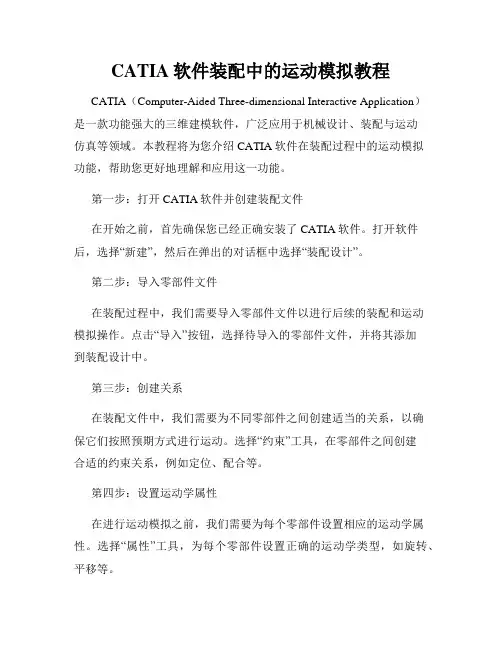
CATIA软件装配中的运动模拟教程CATIA(Computer-Aided Three-dimensional Interactive Application)是一款功能强大的三维建模软件,广泛应用于机械设计、装配与运动仿真等领域。
本教程将为您介绍CATIA软件在装配过程中的运动模拟功能,帮助您更好地理解和应用这一功能。
第一步:打开CATIA软件并创建装配文件在开始之前,首先确保您已经正确安装了CATIA软件。
打开软件后,选择“新建”,然后在弹出的对话框中选择“装配设计”。
第二步:导入零部件文件在装配过程中,我们需要导入零部件文件以进行后续的装配和运动模拟操作。
点击“导入”按钮,选择待导入的零部件文件,并将其添加到装配设计中。
第三步:创建关系在装配文件中,我们需要为不同零部件之间创建适当的关系,以确保它们按照预期方式进行运动。
选择“约束”工具,在零部件之间创建合适的约束关系,例如定位、配合等。
第四步:设置运动学属性在进行运动模拟之前,我们需要为每个零部件设置相应的运动学属性。
选择“属性”工具,为每个零部件设置正确的运动学类型,如旋转、平移等。
第五步:创建运动学关系运动学关系用于定义零部件之间的运动方式,将其连接起来形成一个整体模型。
选择“运动学”工具,在零部件之间创建适当的运动学关系,如齿轮、凸轮等。
第六步:设置运动规则在第五步中创建了运动学关系后,我们需要为整个装配定义运动规则。
选择“运动规则”工具,设置适当的约束和限制条件,以确保装配在运动模拟中的行为符合真实情况。
第七步:进行运动仿真完成以上准备工作后,我们可以开始进行运动仿真了。
选择“运动仿真”工具,在CATIA软件中模拟装配的运动过程,并观察各个零部件的运动轨迹、速度和加速度等参数。
第八步:分析运动仿真结果当运动仿真完成后,我们可以对仿真结果进行分析和评估。
CATIA 软件提供了丰富的可视化和数据分析工具,帮助我们深入了解装配过程中的运动性能和互动关系。
运动仿真学习情况1——旋转副;可以单独驱动,驱动的是旋转角度;只能实现绕自身的轴旋转;√2——棱形副;可以单独驱动,驱动是滑动长度;只能实现沿着公共线滑动;√3——圆柱副;可以单独驱动,可以同时驱动是滑动长度和旋转角度,这两个驱动添加后就可以运动了;只能实现绕轴旋转并沿轴线滑动;√4——螺钉副;可以单独驱动,实现实体每转动1圈,就前进多少mm。
不一定非要是螺杆和螺母,其他的旋转前进仿真也可以使用该命令。
6——平面副;不可以单独驱动,约束一公共平面,具有除沿平面法向移动及绕平面坐标轴转动外的3个运动自由度√7——点曲线副;不可以单独驱动,只能由其他运动副带动起来;点必须在曲线的上面,不在就是不行,实现点在曲线,也就是点在轨迹线上走动。
√8——滑动曲线;不可以单独驱动,只能由其他运动副带动起来;约束两轨迹线相切,实现线在线上滑动;√9——滚动曲线;不可以单独驱动,只能由其他运动副带动起来;约束两轨迹线相切,实现线在线上滑动;√10——点曲面;√不知道他与点曲线有何区别?11——U形结合;√3条轴线相交且位于同一平面内,且输入、输出端轴线与中间轴轴线夹角相同时,可以使用该命令13——齿轮接合;注意齿轮接合的对象不一定是齿轮,只要是一个旋转体带动另一个旋转体的话,就可以使用齿轮接合。
14——齿轮齿条:对旋转副和棱形副进行约束,有个比率15——电缆;√16——刚性结合;√17——使用命令进行模拟√18——使用法则曲线进行模拟√19——机械装置修饰20——装配约束转换√22——分析机械装置23——模拟24——编辑模拟25——重放26——模拟播放器27——编辑序列28——扫略包络体29——轨迹30——重置位置:√仿真的注意点如下:1——驱动对象的选择是有原则的;不可以随便选择,必须符合实际的运动情况;当定义驱动对象时,驱动对象也是有原则的,比如我们在定义旋转副的驱动对象时,如果要求我们的驱动对象进行360度全周旋转的话,那么的我们的对象在实际情况中必须能够或者说可以旋转360度,在整个运动机构当中并不是所有的旋转副都可以旋转360度,有的只能旋转几度,,因此一定要搞清楚哪个对象可以旋转360度,搞清楚这个事情后在去将他定义为驱动对象,如果对象本身不可能旋转360度,而你要把他定义为驱动,还要他旋转360度的话,这样的运动仿真是不成功的。
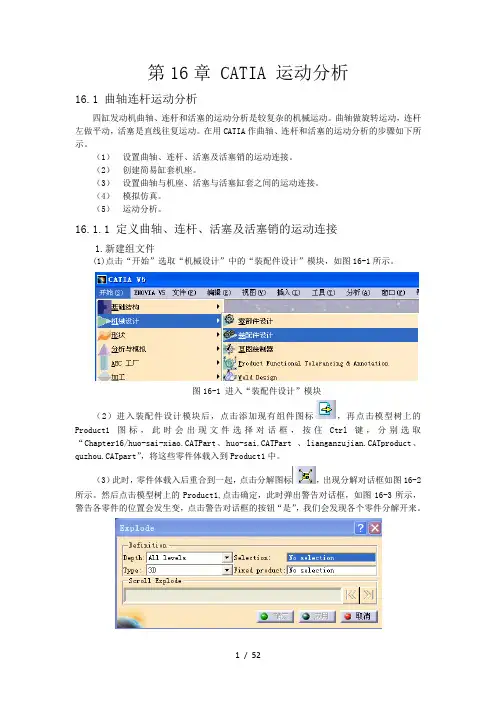
第16章 CATIA 运动分析16.1 曲轴连杆运动分析四缸发动机曲轴、连杆和活塞的运动分析是较复杂的机械运动。
曲轴做旋转运动,连杆左做平动,活塞是直线往复运动。
在用CATIA作曲轴、连杆和活塞的运动分析的步骤如下所示。
(1)设置曲轴、连杆、活塞及活塞销的运动连接。
(2)创建简易缸套机座。
(3)设置曲轴与机座、活塞与活塞缸套之间的运动连接。
(4)模拟仿真。
(5)运动分析。
16.1.1 定义曲轴、连杆、活塞及活塞销的运动连接1.新建组文件(1)点击“开始”选取“机械设计”中的“装配件设计”模块,如图16-1所示。
图16-1 进入“装配件设计”模块(2)进入装配件设计模块后,点击添加现有组件图标,再点击模型树上的Product1图标,此时会出现文件选择对话框,按住Ctrl键,分别选取“Chapter16/huo-sai-xiao.CATPart、huo-sai.CATPart 、lianganzujian.CATproduct、quzhou.CATpart”,将这些零件体载入到Product1中。
(3)此时,零件体载入后重合到一起,点击分解图标,出现分解对话框如图16-2所示。
然后点击模型树上的Product1,点击确定,此时弹出警告对话框,如图16-3所示,警告各零件的位置会发生变,点击警告对话框的按钮“是”,我们会发现各个零件分解开来。
图16-2 分解对话框图16-3 警告对话框(3)由于连杆体零件是装配体,各部分之间存在约束,点击“全部更新”按钮,我们会发现连杆体组件恢复装配后的样子。
(4)点击“约束”工具栏中的“相合约束”图标,分别选择活塞销中心线及活塞孔中心线,如图16-4所示。
然后点击“约束”工具栏中的“偏移约束”图标,选择活塞销的一个端面及活塞孔一侧的凹下去细环端面,如图16-5所示,此时出现“约束属性”对话框,如图16-6所示。
将对话框中的“偏移”一栏改为“3.75mm”,点击“确定”按钮,完成活塞销端面和活塞内凹孔细环端面之间的偏移约束关系。
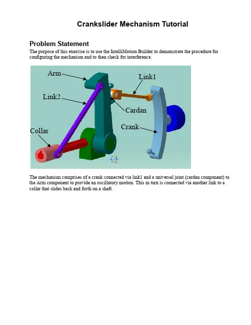
Crankslider Mechanism TutorialProblem StatementThe purpose of this exercise is to use the IntelliMotion Builder to demonstrate the procedure for configuring the mechanism and to then check for interference.Arm Link1Link2CardanCollarThe mechanism comprises of a crank connected via link1 and a universal joint (cardan component) to the Arm component to provide an oscillatory motion. This in turn is connected via another link to a collar that slides back and forth on a shaft.Step 1 Open Model & Set WorkbenchYou will need to run the DDMV5R7 or DDMV5R8 profile shortcut to enable the Dynamic Designer Workbench.Open the product file crankslider_tutorial.CATProduct located in the crankslider sub-folder in the tutorials directory of the installation.If your workbench is not already set to Dynamic Designer (look at the Workbench icon at the top right hand side of the toolbar), then activate the Dynamic Designer Workbench under START – DIGITAL_MOCKUP – DYNAMIC DESIGNER.The Dynamic Designer commands can be accessed via the toolbar icons or the pull down menu (see below)Step 2 Create Mechanism from AssemblyTo auto create the mechanism from the assembly, click on the Convert Mechanism Icon . This will bring up a dialog box asking if you want to convert the assembly constraints when the mechanism is created. Make sure this option is selected before proceeding.The Screen should now look like that below where there are motion entity icons on the graphics screen.Expand the treeview to show the APPLICATIONS – DYNAMIC DESIGNER branches. You should see the following mechanism data:Note that the assembly constraints have been mapped to Dynamic Designer joints and that the grounded parts in the assembly have been automatically made grounded in Dynamic Designer.Step 2 Default Simulation SettingsThe Dynamic Designer Settings can be accessed from two locations.Global settings can be found in the Catia OPTIONS dialog (TOOLS – OPTIONS menu selection)These setting are applied to future mechanisms in different assemblies. We will not be changing these for this exercise, but this is useful to be aware of.Model specific settings can be found by expanding the APPLICATIONS BRANCH of the Catia Treeview, and under the Dynamic Designer Branch, right clicking on the MOTION MODEL branch and selecting the PROPERTIES option. This option can only be done once a mechanism has been started (i.e. a moving or ground part exist). You can also access mechanism settings from the MOTION – MECHANISM settings.We need to change the direction of gravity to match the orientation the model was built in. In this case gravity must act in the –X axis direction. To change this, click on the direction pull down list and select the Standard –X option.STEP 3 Define MotionThe complete mechanism is not designed to operate under gravity, so we need to provide input motion representing a motor connected to the system. Because the joints define how the parts move with respect to one another, we apply motion to the joints as it is clear in which directions the parts can move.To drive the crankslider, we are going to put a motion on the cylindrical joint connecting the Crank to the Crank Housing. In the image shown below, this is joint 4. Please expand the branch under the joint to verify the joint selected is the correct one.Do add a motion, double click on this joint (i.e. Joint.4 in above images) in either the treeview or in the graphics window.Change the MOTION ON from TRANSLATE Z to ROTATE ZChange the MOTION TYPE from FREE to VELOCITYSpecify a CONSTANT velocity of 360 DEG/SECMake sure you click on the RED tick to accept the value change.Press OK to accept the motion definition. You should now see an arrow on the joint in the graphics window.STEP 4 Run SimulationWe are ready to run the simulation. From the MOTION menu select the SIMULATE option to set the simulation settings and to run the solver. Alternatively, you can click on the toolbar icon.Leave the simulation time at 1 seconds and the number of frames at 60. Click on the START button to run the simulations.Once the simulation completes, the analysis dialog will close automatically.STEP 5 Review AnimationWe can now review the results. As part of the simulation, a replay object is automatically generated. You can view the replay by expanding the REPLAY branch at the bottom of the treeview, or by clicking on the toolbar icon.Once the Replay dialog appears, you can review the motion and do all the standard option available in replay like save the animation to file, add an interference analysis, or check for clearances.STEP 6 Interference DetectionInterference checking is done using the DMU utilities in Catia. The first step is to define a DMU Clash Analysis.From the MOTION menu, select the CLASH option. This will bring up the DMU Check Clash dialog.Leave Clash Type as Contact + Clash, but change the selection option to Between Two Selections.Select LINK1 for the Selection1, change focus to Selection 2 and select the ARM componentPress OK to accept and keep this.Arm – Selection 2Link1 –Selection 1To run the analysis, display the REPLAY object . You can view the replay by expanding the REPLAY branch at the bottom of the treeview, or by clicking on the toolbar icon.Click on the EDIT ANALYSIS optionClick on the ADD button to add an analysis to the replay object.Select the Interference.1 analysis to add and press OK. Press OK again to complete adding analyses. On the Replay dialog, change the Interference option from OFF to ON.Press the PLAY button to replay the motion and check for interference while animating (You may notice the parts highlighting while this is happening. This means that clash exists between the parts at that result frame). Once the animation has finished, you will find a new branch under the Replay object called Interference Results.1.You can Double click on this object to review the interference results.NOTE: In some versions of Catia, the interference is not being detected where the lugs are cutting into the side of the arm, even though these parts are highlighted while the analysis is being done.STEP 10 Change Geometry and Re-simulateTo correct the problem, we need to change the geometry of the arm. We will place fillets on the vertical edges of the arm between the two lugs.Double click on the arm to go into part edit mode.From the toolbar select the Edge Fillet icon.Specify a Fillet radius of 0.375 inches (or 9.525 mm)Pick on the 2 vertical edges shown below (you will see the proposed face edges in pink)Press OK to accept the fillets. The geometry should now look like:Return to the Dynamic Designer Workbench by double clicking on the PRODUCT level of the treeview. Repeat the interference check and you should now find that no interference occurs.This concludes the tutorial。
CATIA模型仿真CATIA是一种专业的三维设计软件,广泛应用于航空、汽车、机械等行业。
在设计过程中,模型仿真是不可或缺的一环,它可以帮助工程师评估设计的性能和可行性。
本文将介绍CATIA模型仿真的原理和应用,以及如何进行模型仿真。
一、CATIA模型仿真的原理CATIA模型仿真是基于有限元分析原理的,有限元分析通过将复杂的物体划分成许多个小单元,通过求解各个小单元的力学方程得到整体的力学响应。
CATIA模型仿真主要包括以下步骤:1. 几何建模:在CATIA中,首先需要进行几何建模,即创建物体的几何模型。
这可以通过绘制、拉伸、旋转等操作完成。
2. 材料属性定义:在进行模型仿真前,需要定义材料的力学性质,比如弹性模量、密度等。
CATIA提供了丰富的材料数据库,可以选择合适的材料属性。
3. 网格划分:将几何模型划分成小单元网格,即有限元网格。
网格划分的精细程度决定了计算的准确性和计算速度。
4. 载荷和边界条件定义:在模型仿真前,需要定义载荷和边界条件,即作用在模型上的力、压力、约束等。
这些载荷和边界条件可以通过计算得到,也可以通过实验测量得到。
5. 求解计算:通过有限元分析方法求解模型的力学响应。
CATIA会自动计算每个小单元的应力、应变等参数,并将结果转化为整体的力学响应。
6. 结果分析:CATIA提供了丰富的结果分析工具,可以对仿真结果进行查看、分析和后处理。
比如通过云图、剖面图、动画等方式直观地展示模型的力学响应。
二、CATIA模型仿真的应用CATIA模型仿真在各个领域都有广泛的应用,包括航空航天、汽车、机械等。
以下是几个典型的应用案例:1. 航空航天领域:在飞机结构设计中,CATIA模型仿真可以帮助工程师评估飞机在各种载荷条件下的强度和刚度。
通过对机翼、机身等部件进行仿真分析,可以优化结构设计,提高飞机的安全性和性能。
2. 汽车领域:CATIA模型仿真可以应用于汽车的碰撞仿真、结构强度仿真、疲劳寿命仿真等方面。
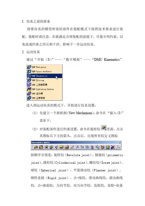
1.仿真之前的准备将要仿真的模型所需的部件在装配模式下按照技术要求进行装配。
装配时请注意,在能满足合理装配的前提下,尽量少用约束,以免造成约束之间互相干涉,影响下一步运动仿真。
2.运动仿真通过“开始(S)”——“数字模拟”——“DMU Kinematics”进入到运动仿真的模式下,开始进行仿真设置:(1)先建立一个新机制(New Mechanism);命令在“插入(I)”菜单下,(2)对装配部件进行约束设置,命令在旋转铰里面,点击其图标右下方的箭头,点击后,出现所有铰定义图标按顺序分别是:旋转铰(Revolute joint),棱镜铰(prismatic joint),圆柱铰(Cylinderical joint),螺纹铰(Screw joint),球铰(Spherical joint),平面滑动铰(Planner joint),刚性连接(Rigid joint),点-线铰,滑动曲线铰,滚动曲线铰,点-曲面铰,万向节铰,双万向节铰,齿轮铰,齿轮-齿条铰,缆绳铰,坐标系铰。
各个铰接的的方法见文献《CATIA 机械运动分析与模拟实例》,上有很详细的介绍。
(3)设置固定件,点击固定零件图标,点击后出现New Fixed Part(新固定零件)对话框,不用理它,在图形区选择要固定的零件即可。
各种铰链设置合理,系统会自动提示:,也就是说,机制可以仿真了。
(a.)仿真使用“命令模拟”时,点击,就会出现运动模拟对话框,在对话框内拖动鼠标,由大到小或有小到大改变角和实数的范围,然后点击下面的黑色开始键,就可以看到仿真运动了。
对话框示例如下(b.)仿真采用“模拟”时,点击,即可进入和将动画视点和自动插入都选上后,用鼠标拖动command 后的命令块由大到小或由小到大改变角和实数的范围,然后点击下面的黑色开始键,就可以看到仿真运动了下面以齿轮运动仿真为例说明:装配过程不多说了,直接进入仿真模块下。
分析:构成:主动齿轮,从动齿轮,侧板使两齿轮运动起来,要用到一个新机制,新机制里有一个齿轮铰,两个旋转铰,一个固定铰,一个驱动。

CATIA模拟仿真入门指南CATIA(Computer Aided Three-dimensional Interactive Application)是一种用于机械设计与制造的三维CAD/CAM/CAE软件。
其中的仿真模块提供了强大的仿真能力,能够帮助工程师在设计阶段进行虚拟验证,从而减少实际制造和测试的成本。
本指南将介绍CATIA模拟仿真的基本原理、常用功能以及使用技巧,旨在帮助初学者快速入门。
一、CATIA模拟仿真概述CATIA模拟仿真是一种基于计算机技术的工程仿真方法,通过使用CAD模型建立虚拟的工程设计环境,对产品进行力学、流体、热传导等物理特性的仿真分析,从而评估并优化设计方案。
它能够模拟真实环境下的物理行为,包括材料的变形、应力的分布、流体的流动等。
CATIA模拟仿真可以应用于各个领域,如汽车、航空航天、能源等。
在设计阶段,它可以评估产品的性能和可靠性,降低产品开发周期,提高设计质量。
在制造和测试阶段,它可以指导加工过程和测试方法,并为产品提供故障诊断和改进的依据。
二、CATIA模拟仿真的基本原理CATIA模拟仿真基于有限元方法(Finite Element Method,FEM)。
在进行仿真分析之前,首先需要进行几何建模,即使用CATIA的建模功能创建产品的三维几何模型。
然后将几何模型导入到仿真模块中,设定材料特性、边界条件和加载条件。
在进行仿真分析时,CATIA会将三维模型分割成无数个小单元,即有限元,并对每个有限元进行力学计算。
通过求解大量的微分方程,得到各个有限元的应力、变形等物理量。
最后,CATIA会将仿真结果以图形和数值的形式呈现出来,帮助工程师分析产品的性能和行为。
三、CATIA模拟仿真的常用功能CATIA模拟仿真提供了多种功能,用于不同类型的仿真分析。
以下是常用的几种功能:1. 结构力学分析:用于评估产品受力情况下的应力、变形等物理量。
可以进行静力学分析、动力学分析、疲劳分析等。
CATIA做运动分析
1.将某一单元的装配图XX-01-00复制一个重命名为:XX-01-motion,打开后将所有参与运动分析的部件以Part文件的形式置于根目录下(其中气缸杆和缸体分为两个Part),并删除所有的约束关系。
2. 将CATIA运行的模式由装配设计模式改为DMU Kinematics模式运行。
3.
4.
5. 双击装配树中的固联双击出现对话框,按下Ctrl+Shift键同时用鼠标选取其
6.
7. 选中铰支点处孔中心线对孔中心线,再选中两个在同一
8. 选中气缸旋转点处孔中心线对孔中心线,再选中两
9. 选中气缸铰接头处孔中心线对孔中心线,完成后点
10.
11.
行运动快慢的调节(数值为总运动过程所分的步数)。
12. 运动完成点
13.删除非运动部件,保存。
14.在装配设计下打开XX-01-00单元,将XX-01-Motion装入,编辑颜色使用。
本单元运动分析完成。
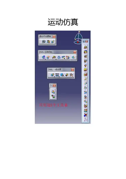
产品研发一部底盘室:马学超题目:CATIA的DMU运动机构模块功能介绍CATIA—DMU运动机构CATIA DMU 运动机构•对于产品的数字模型而言,进行准确的机构运动及状态分析,是十分基本并且重要的功能。
在DMU运动机构系统中,我们可以依照运十分基本并且重要的功能在运动机构系统中我们可以依照运动学的原理,通过约束自由度的方式建立机构,并且分析机构的运动状态与移动轨迹;态与轨•本文主要提供几种基本的结合,使我们建立机构运动,并且可以本文主要提供几种基本的结合使我们建立机构运动并且可以进行动态仿真,记录运动情形,制作成影片播放;CATIA DMU运动机构CATIA—DMU 运动机构•模块简介:CATIA—DMU运动机构CATIA DMU 运动机构•功能键一览:功能键览CATIA DMU 运动机构CATIA—DMU运动机构•过程:—————将装配件导入DMU模块建立机械装置分析运动结合类型—建立运动结合——约束固定件——设置驱动形式——(两种做法运动仿真):运动仿真)1、使用命令进行模拟(可编辑传感器,导出数据,并绘制图形);2、模拟(可生成自动播放动画,也可编辑传感器)——可通过编译模拟,生成重放,——生成包络体;CATIA DMU 运动机构CATIA—DMU运动机构•运动结合点:运动结合点从左至右结合类型依次为::旋转结合;:棱形结合;:圆柱结合;:螺钉结合;:球面结合:平面结合;:刚性结合;:点线结合;:滑动曲线结合;:滚动曲线结合;:点面结合;:通用结合;:CV结合;:齿轮结合;:架子结合;:电缆结合;:基于轴的结合;CATIA—DMU 运动机构CATIA DMU 运动机构•:旋转结合1、点击按钮,弹出右图1窗口;图12、点击右上角“新机械装置”,弹出图2窗口;图23、单击“确定”按钮,弹出图1窗口图3CATIA DMU 运动机构CATIA—DMU运动机构4、图中“直线1”、“直线2”、“平面1”、“平面2”依次选取螺栓轴线、螺母轴线、螺栓垂直轴线平面、螺母垂直轴线平面,螺栓一垂直轴线平面、螺母一垂直轴线平面,并点击“偏移”与“驱动角度”按钮,如右图4显示,并单击“确定”图4CATIA DMU 运动机构CATIA—DMU运动机构5、单击中的按钮,弹出右图所示窗口,然后直接左键单击螺弹出右图所示窗然后直接左键单击螺栓part,这时系统会出现“可以模拟机械装置”提示,点击确定CATIA—DMU运动机构CATIA DMU 运动机构6、在左侧树中双击图中高亮显示的旋转结合,在左侧树中双击图中高亮显示的“旋转”结合,便会弹出如右图5所示窗口,在窗口‐360deg和+360deg处可修改角度范围,修改完点击确定;(注意此时机械装置自由度=0,若不为0是不能仿真的,此项尤为重要,下述每个结合均是如此,不再反复强调)图5CATIA—DMU运动机构CATIA DMU 运动机构点中使用7、点击中的(使用命令进行模拟)按钮,弹出右图6所示窗口,点击“模拟”下的“立刻”按钮,便可拖动上面的游标随意旋转;也可使用“按需要”命令,修改一下右上角数字框中的数据,就可点击下方的箭头标示,使构件自行转动;图6箭头标示使构件自行转动CATIA—DMU运动机构CATIA DMU 运动机构•:棱形结合棱形结合1、单击(棱形结合)按钮,弹出如右图1所示窗口单击(棱形结合)按钮弹出如右图图12、点击右上角“新机械装置”按钮,弹出图2所示窗口图2 3、单击确定按钮,图1窗口变为图3所示窗口,图3CATIA—DMU运动机构CATIA DMU 运动机构4、窗口中“直线1”、“直线2”、“平面1”、“平面2”、分别选择螺栓轴线、螺母轴线、螺栓中的zx平面、螺母中的zx平面(所选平面必须与所选直线平行),并点选“驱动长度”按钮,如右图4所示,并单击确定;图4CATIA DMU 运动机构CATIA—DMU运动机构5、单击中的按钮,弹出右图所示窗口,然后直接左键单击螺弹出右图所示窗然后直接左键单击螺栓part,这时系统会出现“可以模拟机械装置”提示,点击确定CATIA—DMU 运动机构CATIA DMU 运动机构6、在左侧树中双击图中高亮显示的“棱形”结合,所示窗在窗便会弹出如右图5所示窗口,在窗口‐100mm 和100mm 处可修改长度范围,修改完点击确定;图5CATIA—DMU运动机构CATIA DMU 运动机构点中使用7、点击中的(使用命令进行模拟)按钮,弹出右图6所示窗口,点击“模拟”下的“立刻”按钮,便可拖动上面的游标随意移动;也可使用“按需要”命令,修改一下右上角数字框中的数据,就可点击下方的箭头标示,使构件自行移动;图6箭头标示使构件自行移动CATIA—DMU 运动机构CATIA DMU 运动机构•圆柱结合单击(圆柱结合)按钮弹出如右图图11、单击(圆柱结合)按钮,弹出如右图1所示窗口图22、点击右上角“新机械装置”按钮,弹出图2所示窗口3、单击确定按钮,图1窗口变为图3所示窗口,图3CATIA—DMU 运动机构CATIADMU 运动机构线、螺母轴线,并点选“驱动角度”、“驱动长度”按钮如右图所示并单击确定圆长度”按钮,如右图4所示,并单击确定;(圆图4柱)结合从动件既可沿轴向转动,也可同时沿轴向移动);CATIA DMU 运动机构CATIA—DMU运动机构5、单击中的按钮,弹出右图所示窗口,然后直接左键单击螺弹出右图所示窗然后直接左键单击螺栓part,这时系统会出现“可以模拟机械装置”提示,点击确定CATIA DMU 运动机构CATIA—DMU运动机构6、在左侧树中双击图中高亮显示的“圆柱面”结合,便会弹出如右图5所示窗口,在窗口‐100mm和所示窗在窗100mm处可修改长度范围,在窗口‐360deg和360deg处可修改角度范围,修改完点击确定;图5CATIA—DMU运动机构CATIA DMU 运动机构点中使用7、点击中的(使用命令进行模拟)按钮,弹出右图6所示窗口,点击“模拟”下的“立刻”按钮,便可拖动上面的游标随意移动和转动;也可使用“按需要”命令,修改一下右上角数字框中的数据,就可点击下方的箭头标示,使构件自行移动和转动;图6据就可点击下方的箭头标示使构件自行移动和转动CATIA—DMU 运动机构CATIA DMU 运动机构•螺钉结合单击(螺钉结合)按钮弹出如右图图11、单击(螺钉结合)按钮,弹出如右图1所示窗口图22、点击右上角“新机械装置”按钮,弹出图2所示窗口3、单击确定按钮,图1窗口变为图3所示窗口,图3CATIA—DMU运动机构CATIA DMU 运动机构4、窗口中“直线1”、“直线2”分别选择螺栓轴线、螺母轴线,并点选“驱动角度”、或“驱动长度”按钮,如右图4所示,并单击确定;(螺钉结合可通过驱动角度和螺距的设置控制运动,也可通过驱动长度的设置控制运动);动也可通过驱动长度的设置控制运动)图4CATIA—DMU运动机构CATIA DMU 运动机构5、单击中的按钮,单击弹出右图所示窗口,然后直接左键单击螺栓part,这时系统会出现“可以模拟机械装提示点击确定;装置”提示,点击确定;CATIA DMU 运动机构CATIA—DMU运动机构6、在左侧树中双击图中高亮显示的“螺钉”结合,便会弹出如右图5所示窗口,在窗口“螺距”处所示窗在窗“螺距”处可修改螺栓螺母的螺距,在窗口‐360deg和360deg处可修改角度范围,修改完点击确定;图5CATIA—DMU运动机构CATIA DMU 运动机构点中使用7、点击中的(使用命令进行模拟)按钮,弹出右图6所示窗口,点击“模拟”下的“立刻”按钮,便可拖动上面的游标随意移动和转动;也可使用“按需要”命令,修改一下右上角数字框中的数据,就可点击下方的箭头标示,使构件自行移动和转动;图6据就可点击下方的箭头标示使构件自行移动和转动CATIA—DMU 运动机构CATIA DMU 运动机构•球面结合(球头连接)单击(螺钉结合)按钮弹出如右图图11、单击(螺钉结合)按钮,弹出如右图1所示窗口图22、点击右上角“新机械装置”按钮,弹出图2所示窗口3、单击确定按钮,图1窗口变为图3所示窗口,图3CATIA—DMU 运动机构CATIA DMU 运动机构4、在窗口中,点1点选球头面,自动识别球心;在窗口中,点点2点选球套面,自动识别球心位置,如右图所示可先在p中建球点4所示,也可先在part 中建立球心点,前后然后点选时只需直接选取点就行,选选取完之后点击确定,点击确定之后,两球心会相合在一起;4图CATIA DMU 运动机构CATIA—DMU运动机构5、单击中的按钮,此时系统并未自动弹出“可以模拟机械装置”窗口,在树中打开“机械装置”,发现此时的自由度=3,并不等于0,所以只有球面结合和固定件的情况下,是“球面结合”和“固定件”的情况下是不能进行仿真的,“球面结合”必须和其他带有驱动性质的结合一起使用;CATIA DMU 运动机构CATIA—DMU运动机构•平面结合平面结合和球面结合的步骤基本一样,并且只是约束平面结合和固定件的话机械装置的自由度也不为0,需要和别需要和别的带有驱动性质的结合在一起使用;的带有驱动性质的结合在起使用CATIA—DMU运动机构CATIA DMU 运动机构•刚性结合刚性结指将零件具有动式零件刚性结合是指将零件与已经具有运动形式的零件固定在一起,与其做相同的运动,或是与固定件绑定在一起不做运动;窗口中的“零件1”选择已经具有运动形式零件,“零件2”选择要与之刚性结合的零件;CATIA—DMU运动机构CATIA DMU 运动机构•点曲线结合点曲线结合是指一个part以本身的一个点与另外一各part点曲线结合是指个t以本身的个点与另外各t 中的一条曲线连接点沿着曲线方向移动中的一条曲线连接,点沿着曲线方向移动;CATIA—DMU运动机构CATIA DMU 运动机构将曲线固定后,这时系统并不会提示“可以模拟机械装置”,如右图所示,机械装置的自由度=3,并不为0,因为点所在的part并没限制本身的旋转自由度,所以点曲面结合也需要与其他具有驱动特性的结合配合使用;CATIA DMU 运动机构CATIA—DMU运动机构•滑动曲线结合滑动曲线结合,顾名思义就是一条曲线沿着另一条曲线滑动,但仅仅曲线沿着另一条曲线滑动但仅仅约束滑动结合,机械装置的自由度还不为0,必须要与其他形式的结合配合使用;CATIA DMU 运动机构CATIA—DMU运动机构•滚动曲线结合滚动曲线结合,顾名思义就是一条曲线沿着另一条曲线滚动,但仅仅曲线沿着另一条曲线滚动但仅仅约束滚动结合,机械装置的自由度还不为0,必须要与其他形式的结合配合使用;CATIA DMU 运动机构CATIA—DMU运动机构•点曲面结合点曲面结合,顾名思义就是一个点在一个曲面上运动,但这是远远不够的,无论是方向还是转动的自由度都没有约束完全,方向还是转动的自由度都没有约束完全所以是不能够模拟仿真,也需要与其他形式的结合一起使用;CATIA DMU 运动机构CATIA—DMU运动机构•通用结合通用结合是两个旋转结合的复合,将第一个旋转结合进行驱动的设置,第二个旋转不用设置驱动,通过通用结合,就是将第二个旋转结合的旋转零件的轴线与第个旋转结合的旋转零件的轴线连接起来,成为第个旋转件的轴线与第一个旋转结合的旋转零件的轴线连接起来成为第一个旋转零件的从动件;具体操作如下:CATIA DMU 运动机构CATIA—DMU运动机构1、在蓝色零件和灰色零件之间建立旋转结合,命名为“旋转1”,并设置“驱动角度”;CATIA DMU 运动机构CATIA—DMU运动机构2、分别在绿色零件与灰色零件、浅蓝色零件和灰色零件之间建立旋转分别在绿色零件与灰色零件浅蓝色零件和灰色零件之间建立旋转结合,分别命名为“旋转2”、“旋转3”,这两个旋转都不设置“驱动角度”,并将灰色零件设置为固定件;旋转2旋转3CATIA DMU 运动机构CATIA—DMU运动机构3、点击(通用结合)按钮,出现如下图所示窗口,“旋转1”处选择蓝色零件轴线,“旋转2”处选择绿色零件轴线,“十字销轴线方向”选择“垂直于旋转2”,点击确定;CATIA DMU 运动机构CATIA—DMU运动机构4、重复使用通用结合,如下图所示:“旋转1”选择绿色零件轴线,“旋”选择浅蓝色零件“十字销轴线”选择“垂直于旋转”点击确转2选择浅蓝色零件,十字销轴线选择垂直于旋转1,点击确定之后,系统便会提示“可以模拟机械装置”;CATIA—DMU运动机构CATIA DMU 运动机构操作完成后,具体树的情况见右图,图中两个U形接合右图,图中两个“形接合”便是通用结合;CATIA DMU 运动机构CATIA—DMU运动机构•CV结合CV结合与通用结合一样,CV结合只是可以同时识别连接三个旋转结合,并且也是只需第一个旋转结合设置驱动角度就行,后两个旋转结合都是随动件;CATIA DMU 运动机构CATIA—DMU运动机构展开左边的树可以发现展开左边的树,可以发现,cv结合就是两个通用结合的复合,而通用结合就是两个旋转结合的复合;CATIA DMU 运动机构CATIA—DMU运动机构•齿轮结合齿轮结合也是复合结合,也要识别两个旋转结合,所以首先要在两个齿轮和支座之间建立旋转结合;CATIA—DMU运动机构CATIA DMU 运动机构点击齿轮结合,窗口中的旋转结合1、口中的“旋转结合”“旋转结合2”分别要在树中选取;比率填写小齿轮与大齿轮的分度圆直径比;旋转方向,紧挨着的两个齿轮方向相反,若两齿轮间默认有中间齿轮话,则方向相同;驱动角度依据具体情况选取主从动关系;CATIA—DMU运动机构CATIA DMU 运动机构•架子结合架子结指就轮架子结合指的就是齿轮齿条的运动结合,也是复合结合,首先要在齿条和支座之间建立棱形结合,在齿轮和支座之间建立旋转结合,建立完成之后,如右图树中所示;CATIA DMU 运动机构CATIA—DMU运动机构点击架子结合,弹出右上图,“棱形结合”处在树中选择“棱形.1”,“旋转结合”选择“旋转.2”;比率处选择定义,弹出右中图所示窗口,“半径”处选取齿轮分度圆直径,窗口会自动生成比率,点击确定,会转至右图下所示窗口;驱动方式的地方,根据具体情况选取“棱形的驱动长度”或是“旋转示窗口驱动方式的地方根据具体情况选取“棱形的驱动长度”或是“旋转的驱动角度”,点击确定完成,即可模拟仿真;CATIA—DMU运动机构CATIA DMU 运动机构•电缆结合电缆结合是指将两个滑块用虚拟滑轮通过虚拟滑轮连接起来,所以要先在绿色滑块与支撑座、蓝色滑块与支撑座之间建立棱形结合,并在“棱形1”结合中设置驱动长度,将支撑座设置为固定件;CATIA DMU 运动机构CATIA—DMU运动机构点击按钮,弹出如右上图所示窗口,图中“棱形结合1”在左边树中选取“棱形.1”,“棱形结合2”在树中选取“棱形.2”,比率根据实际数据进行填写,驱动方式选取“棱形1的”驱动长度,设置完之后点击确定,会提示“可驱动长度设置完之后点击确定会提示“可以模拟机械装置”;。
运动分析的一般步骤运动分析在Catia V5 R12中的DMU Kinematics模块下的一般步骤1.创建机构运动分析不是针对单个实体的分析,而是针对一个或多个机构的分析,所以应该先确定一个机构。
通常先确定一个固定件,否则机构是不能运动的。
点击Fixed Part命令,出现如下对话框:在几何模型区,或者树形图上选择想要固定的部件,这时定义好的机构自动出现在树形图上。
2.定义约束依据下表选择合适正确的运动副。
RollSlidePointPointJointJoint一个机构要想运动,通常会有一个或多个驱动,具体要根据机构形式而定。
可以在第二步定义约束的同时进行驱动命令的定义。
例如对于圆柱副,既可以定义角度驱动,又可以定义长度驱动,或者同时定义角度驱动和长度驱动。
完全约束的条件:每个运动副约束的自由度不同,而每个驱动命令只能约束一个自由度,当机构的自由度为零时,为完全约束(小于零为过约束,大于零为欠约束);这时系统会提示你,机构已经可以模拟了:4.设置传感器设置传感器来监测动态仿真过程,比如间隙值、碰撞、速度和加速度等。
在动态仿真过程中,可以根据传感器测量的数据来分析检查样机的设计情况。
常用以下几个命令Clash (碰撞分析);Distance & Band Analysis (距离和区域分析);Speed and Acceleration (速度和加速度测量)等。
(1)距离和区域分析:用于测量一个组内或者两个组内物体之间的最小距离。
在装配或运动分析中还可以进行动态测量。
点击命令: Name :自定义名称或者选择默认名称;Type :测量类型,一共有5种;Mimimum ,Along X ,Along Y ,Along Z ,Band Analysis定义驱动命令计算类型,有三种;Between two selection 在两个选择物体之间;Inside one selection 在一个选择物体之内;Selection Against All 选择物体与所有未选择的物体之间。
1.仿真之前的准备
将要仿真的模型所需的部件在装配模式下按照技术要求进行装配。
装配时请注意,在能满足合理装配的前提下,尽量少用约束,以免造成约束之间互相干涉,影响下一步运动仿真。
2.运动仿真
通过“开始(S)”——“数字模拟”——“DMU Kinematics”
进入到运动仿真的模式下,开始进行仿真设置:
(1)先建立一个新机制(New Mechanism);命令在“插入(I)”
菜单下,
(2)对装配部件进行约束设置,命令在旋转铰里面,点击其图标右下方的箭头,点击后,出现所有铰定义图标
按顺序分别是:旋转铰(Revolute joint),棱镜铰(prismatic joint),圆柱铰(Cylinderical joint),螺纹铰(Screw joint),球铰(Spherical joint),平面滑动铰(Planner joint),
刚性连接(Rigid joint),点-线铰,滑动曲线铰,滚动曲线
铰,点-曲面铰,万向节铰,双万向节铰,齿轮铰,齿轮-齿条
铰,缆绳铰,坐标系铰。
各个铰接的的方法见文献《CATIA 机械运动分析与模拟实例》,上有很详细的介绍。
(3)设置固定件,点击固定零件图标,点击后出现New Fixed Part(新固定零件)对话框
,不用理它,在图形区选择要固定的零件即可。
各种铰链设置合理,系统会自动提示:
,也就是说,机制可以仿真了。
(a.)仿真使用“命令模拟”时,点击,就会出现运动模拟对话框,在对话框内拖动鼠标,由大到小或有小到大改变角和实数的范围,然后点击下面的黑色开始键,就可以看到仿真运动了。
对话框示例如下
(b.)仿真采用“模拟”时,点击,即可进入
和
将动画视点和自动插入都选上后,用鼠标拖动command 后的命令块由大到小或由小到大改变角和实数的范围,然后点击下面的黑色开始键,就可以看到仿真运动了
下面以齿轮运动仿真为例说明:
装配过程不多说了,直接进入仿真模块下。
分析:
构成:主动齿轮,从动齿轮,侧板
使两齿轮运动起来,要用到一个新机制,新机制里有一个齿轮铰,两个旋转铰,一个固定铰,一个驱动。
1.在“插入(I)”下,点击新机制命令,可以看到左侧目录树
Application下添加了Mechanisms——Mechanism.1.
2.添加两个旋转铰;点击,出现下面对话框
在Line 1后的空格选择主动齿轮的轴线,
在Line 2后的空格选择侧板孔(安装z z zz 主动齿轮的那个孔)的轴线,
在Plane 1后的空格选择主动齿轮(与侧板相合的那面)的端面,
在Plane 2后的空格选择侧板(与主动齿轮相合的那面)的端面,
点选Angle driven,然后确定即可。
重复上面步骤给从动齿轮添加旋转铰,这里注意:从动齿轮不能点选Angle driven,因为它要被主动齿轮带动。
3. 添加齿轮铰:点击,出现下面命令框
,在这里点选齿轮铰,出现齿轮铰的对话框如下:
在Revolute Joint 1后的框里点选刚刚创建的主动齿轮旋转铰Revolute Joint 1;
在Revolute Joint 2后的框里点选刚刚创建的从动齿轮旋转铰Revolute Joint 2;
Ratio定义为-1,以为主从齿轮转向相反;
点选Angle driven for revolute 1.就是主动轮驱动。
4.添加固定铰:点击,然后用鼠标选中侧板即可。
这时,系统会提示,可以进行仿真了。
5.运动仿真:点击或者都可以。
分别阐述
点击时,出现下面的对话框
这时,系统一般默认命令角度范围是:-360—— 360,点击角度后的可以修改范围,我修改为0——360.
在框的下部,要点选On request,否则你拖动游标时,系统无法记录运动过程。
这些完成后,拖动游标,仿真就开始了。
至于Number of steps,是步数,越大回放时越慢,您可以自己设定不同的值试一试。
点击仿真时,出现
选择机制才能进行仿真,如图,确定。
确定后出现
和
按照图示点选后,即可拖动游标,仿真开始,编辑模拟框将会自动记录下运动过程,拖完以后,可看到编辑模拟框的灰键变黑,表示可以点击回放了。
回放结束后,按确定键,系统将会记录下这次仿真,待以后回放。
在
模型树可以看到
祝你好运,身体健康!。