海高思远程监控和运维平台演示教学
- 格式:ppt
- 大小:16.60 MB
- 文档页数:41

xxxx运维监控管理平台操作手册V1.0 xxxx(天津)科技有限公司变更记录序号版本变更说明修改人/日期01 V1.0 新建张冠洲/2017年1月目录1.平台简介 (4)1.1概述 (4)1.2平台功能 (4)1.3优劣势 ................................................................................................... 错误!未定义书签。
2.安装部署 (4)2.1服务端环境准备 (4)2.2数据库准备 (5)2.3编译安装 (5)2.4配置文件及WEB前端文件修改 (5)2.5WEB前端安装配置 (6)2.6启动S ERVER (7)2.7在HOSTS上配置AGENT (8)3.配置使用 (9)3.1添加H OSTS (9)3.2添加I TEMS (10)3.3添加T RIGGERS (11)3.4添加A CTIONS (12)3.5添加M EDIAS (13)3.6添加U SERS (13)3.7添加WEB M ONITORINGS (14)3.8添加G RAPHS (17)3.9添加S CREENS (18)3.10添加M APS (18)3.11添加SNMP监控 (19)3.12添加自定义监控 (20)3.13添加T EMPLATES (20)3.14添加R EPORTS(定制报表) (20)3.15添加M ACROS (22)3.16添加自动发现设备 (22)3.17添加I NVENTORY (22)3.18E XPORT/I MPORT XML (23)3.19M AINTENANCE(维护时间) (24)1.平台简介1.1概述xxxx运维监控管理平台根据自身业务需求进行开发以满足平台监控业务需要。
平台通过C/S模式采集数据,通过B/S模式在web端展示和配置。
被监控端:主机通过安装agent方式采集数据,网络设备通过SNMP方式采集数据Server端:通过收集SNMP和agent发送的数据,写入MySQL数据库,再通过php+apache在web前端展示。


远程互动教育录播系统VJES使用手册REV688南京纳加软件股份有限公司版权所有,不得翻印目录一、纳加远程互动教育录播系统(VJES1.1) (1)1.1监视 (1)1.2通道 (1)1.3输出 (9)1.4调音台 (20)1.5导播规则 (21)1.6云教室 (24)1.7云台 (26)1.8字幕 (28)1.9角标 (29)1.10CG (29)1.11切换控制 (31)1.12切换特技 (32)1.13上传 (32)二、桌面采集客户端(VJTeacher) (34)2.1安装 (34)2.2运行 (35)2.3桌面采集 (35)2.4远程控制 (36)2.5手写板 (36)2.6音频设置 (37)2.7开始/停止课件录制 (38)2.8录播机开机/关机 (39)2.9课件信息设置 (39)2.10图像质量设置 (40)三、课件录制 (41)3.1课件格式 (41)3.2本地播放 (41)3.3网络在线播放 (41)3.4课件播放器 (42)3.4.1.界面布局 (42)3.4.2.显示模式 (42)3.4.3.PPT索引 (43)3.4.4.笔记 (43)四、附录 (44)4.1录播操作台NDCP-L使用说明 (44)4.2片头、片尾的制作方式和关联使用说明 (47)4.3ONVIF测试工具及方法 (51)4.4常见问题 (52)一、纳加远程互动教育录播系统(VJES1.1)1.1监视1)显示系统当前时间。
2)主监:红色代表主监,监看正在播出的画面。
3)预监:绿色代表预监,监看即将播出的画面。
4)播放音频时的音量指示条。
5)系统状态信息。
1.2通道1)VGA:加载授课机桌面,可以通过采集卡或者VJTeacher软件接入。
2)老师:加载老师摄像机,通过采集卡接入,也可以通过IP摄像机的数据流接入。
3)学生:加载学生摄像机,通过采集卡接入,也可以通过IP摄像机的数据流接入。
4)全景:加载全景摄像机,通过采集卡接入。


xxxx运维监控管理平台操作手册V1.0xxxx( 天津) 科技有限公司变更记录目录1.平台简介.................................................................... 错误!未定义书签。
1.1 概述........................................................................错误!未定义书签。
1.2 平台功能................................................................错误!未定义书签。
1.3 优劣势....................................................................错误!未定义书签。
2.安装部署.................................................................... 错误!未定义书签。
2.1 服务端环境准备....................................................错误!未定义书签。
2.2 数据库准备............................................................错误!未定义书签。
2.3 编译安装................................................................错误!未定义书签。
2.4 配置文件及WEB前端文件修改...........................错误!未定义书签。
2.5 WEB前端安装配置................................................错误!未定义书签。


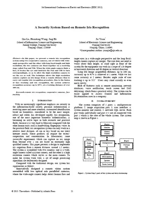
A Security System Based on Remote Iris RecognitionSha Lu, Huaideng Wang, Jing He School of Information Science and Engineering Jinling College, Nanjing UniversityNanjing, China, 210089Jie Yuan*School of Electronic Science and EngineeringNanjing UniversityNanjing, China, 210093*CorrespondentAuthor:***************.cnAbstract—In this paper, we present a remote iris recognition system using two cooperative cameras, one of which with wide-angle perspective and the other with long focal-length and high resolution; the two cameras are fixed together on a resolving stage called Pan and Tilt. When the wide-angle camera finds a face, it locates the eye and instructs the Pan and Tilt to turn correspondingly, so as to allow the high resolution camera to see the eye as well. The technique allows the high resolution camera capture an iris image from a remote distance then to carry out regular iris recognition procedure. Due to the fusion of face tracking and iris recognition, the system achieves recognition accuracy up to 95%, at a working distance of over 100 cm.Keywords-remote iris recognition, cooperative cameras, face trackingI.I NTRODUCTIONWith an increasingly significant emphasis on security in the information-based society, personal authentication is receiving more and more attention. Automated identification based on biometrics, considered to be the most unique, robust and stable, has developed rapidly. Iris recognition, one of the most important biometric authentications, is becoming an active topic in both research and practical fields, because it is very hard to fabricate compared with the other human traits such as handwriting, fingerprint, voice. In the practical field, iris recognition system can only work in a relative short distance, 40 cm or less based on our latest Internet search. These products all require the testers’ cooperation and concentration. In laboratories, some successful experiments which can capture an iris image from beyond over 1 cm are based on extremely high qualified camera. This paper presents a design to implement iris cognition from a remote distance, around 1.5 meters. The system is assembled with two cameras: one is a wide-angle camera called assistant camera, and the other is a high resolution camera which serves as the main camera. To make the system work well, a set of image processing algorithms are deliberately designed.Compared with the traditional design, our system has superiorities as follow:Innovatively designed a remote vision system assembled with two optical axis paralleled cameras, where the wide-angle camera helps detect human face and target eyes in a wide-angle perspective and the long focal-length camera capture iris images. The user does not need to worry about their height, or stand right in front of the system for the equipment can work in a scope of 120 degree in horizontal direction and 60 degree in vertical direction.Long iris image acquisition distance, up to 200 cm. Accuracy up to 95% is achieved at 1 meter, while we lost some accuracy at 2 meters. Besides angle scale of user tracking is up to 355°.Users may stand casually or even move slowly.Rich of features such as remote monitoring, network databases, voice notification, touch screen and SMS delivering, which form a practical utility. The system can be easily applied to Access Control and Information Dissemination Area in a company.II.S YSTEM O VERVIEWThe system comprises of 5 parts: 1. multiprocessor platform; 2. image acquisition part; 3. user interface; 4. system monitor and control; 5. network SQL server. Each part works individually and part 2~5 are all connected with part 1 which is the core of the whole system. The system map is shown in Figure 1.Figure 1. System Map:5 parts of the system and their relationship3rd International Conference on Electric and Electronics (EEIC 2013)Part 1 takes most of the computing tasks including image processing, device control etc. An operating system is embedded in the platform. This platform also provides necessary standard interfaces for other parts. Part 2 comprises of 2 CCD digital cameras and a resolving stage called Pan and Tilt. One camera has wide optic-angle (as assistant camera below), the other camera has long focal-length and high resolution (as high-resolution camera below).The Pan and Tilt rotates both vertically and horizontally, and can be controlled by part 1 with certain instructions. Both cameras are fixed on the Pan and Tilt like shown in Figure2. Part 3 includes touch screen, speaker and a GSM module to send short messages. Part 4 includes a monitor and some general inputs. Part 5 is connected withpart 1 through network.Figure 2. The image acquisition partThe functions of the system are listed as follows:a) Real-time face tracking and eye positioning: Facedetection and eye positioning can be processed in the rate of 30 fps. So the visitor's eye is tracked dynamically and can be locked in 5 seconds. The system functions well against illumination and under multi-people situation.b) Iris image acquisition and recognition: the systemdetects a human face automatically and tracks it, after a certain process the visitor's iris will be recognized. c) User interactive: This part takes responsibility ofanswering for visitor's request and give prompt. Also visitors can make a quick registration into the system. d) Local administration: Administrators of the system canmonitor the status of the system, including details of face tracking and iris recognition. Administrators can make necessary adjustment of parameters, such as optical adjustment, skin color threshold and available scales of rotary table.e) Network identification database: Identificationdatabase is published by a network SQL server. All similar systems share 1 database on this server.When a visitor wants to get into the security system, one could use the touch screen to send a signal to the system. After that the system starts its process automatically: 1. the assistant camera captures an image and judges where the human face is. 2. Then human eyes is also positioned; 3. Based on the position of the human eyes, the systemcontrols the Pan and Tilt in order to focus one human eye. 3. After a close loop control process, the high-resolution camera captures an image with a human eye, which takes more than 60% of whole image. In this image the eyeball can be accurately positioned; 4.The last step is to get the iris image from the eyeball image and recognize it. If this visitor has been registered, the touch screen displays information of the matching result and a welcome message is sent to the visitor’s cell, otherwise this visitor will be rejected.III. I MPLEMENTATION OF A LGORITHMA. Face TrackingGenerally, this part follows 3 steps (i) Skin Region Detection, (ii) Face Candidate Localization (iii) Final Decision. In step (i) the source image is transformed from RGB color space into YCbCr color space, and the skin region can be segmented. Finally we get a binary image in this step. In step (ii) Median filter and morphological closing are applied to the binary image. All connected regions are located after a global scanning. In step (iii) any region without right geometry or area is eliminated, the largest region of the rest is the human face region. After that the rotary table moves to ensure human face region at the center of the whole image.B. Eye PositioningAccording to a face gray image, it is easily to Figureure out that eyes are in the least brightness and have the most details. In another word, eyes have a low brightness value and a high gradient value at the same. To joint analyses of gray images and gradient images, we applied a union evaluate function as follow:(,)(,)(,)G x y I x y S x y =(1)Then we divided the gradient value by a gray value at each pixel, thus the eye pixels were easily found for their values were much higher. Meanwhile, we also followed the geometry characteristic of faces to exclude eyebrows and nostrils, and consequently precisely targeted the eye. The transformed images are shown in Figure.3. Analysis onimage I is shown in Figure4.(a) (b) (c) (d)Figure 3. (a) is source image (b) and (c) are S and G image.(d) is I imagewhich is for joint analysis.Figure 4. Projection method to locate eyes: project binary image into both xand y coordinate and find the peak value.C.Iris PositioningThis step concerns on eyeball location. First of all the gray image is thresholded, after median filter and morphological closing are applied to it, we get several candidate regions. Then eye ball region is told apart from hair, eye bow and others by geometry, area and relative location. In the eyeball region, the image is thresholded and results in a binary image which Then Canny operator is applied to and results in the circular edge of the pupil. After noise removal and smoothing the edges, circular Houghtransform is applied to locate the pupil.Figure 5. Steps to locate irisD.Iris RecognitionThe iris recognition technique applied in this work iscomposed of three stages: preprocessing stage, featureextraction stage and matching stage.In the preprocessing stage, after using Canny edgedetection to find edges, we applied a Hough transform tolocate the iris region. Then, we remapped each point withinthe iris region to a pair of polar coordinates, so that theregion has a fixed dimension, following which we applied aHistogram Equalization.In the second stage, we used a Gabor filters to extractionthe iris pattern and obtain a feature vector. A general 2-dimension Gabor filter is shown as follow:()()ee yvxuyyx0-xy,xG02222yxj2--⎥⎦⎤⎢⎣⎡⎟⎠⎞⎜⎝⎛−+−⎥⎥⎥⎦⎤⎢⎢⎢⎣⎡+⎟⎠⎞⎜⎝⎛−⎟⎠⎞⎜⎝⎛=ππβα(2)In the matching stage, we compared the feature vectorextracted from the iris with the ones stored in the databaseby calculating their Vector Similarity using:(,)||||*||||k jk jk jx xd x xx x•=(3)where xk is the vector of the tested iris, xj is one of the iristemplates, and d is the similarity of the two vectors. If thetwo vectors are derived from the same iris, the d will beclose to 1, otherwise to 0.Figure 6. Iris image and the image filtered by GaborUltimately, the filtered image is projected into a vector oflength 512. Euler distance from vectors in the database iscalculated one by one, before the matching result is given.IV.E XPERIMENTWe tested the Eye Targeting module in differentconditions, and the results are presented in Table 1.TABLE I. S UCCESS RATIO OF FACE DETECTION AND EYEPOSITIONING UNDER DIFFERENT CONDITIONS SUCH AS DIFFERENTILLUMINATION.TestingConditionSuccess Ratio ofFinding Face %Success Ratio ofLocating Eyes%Soft light 100.0 98.5Against light92.5 78.1Large-anglerotated face97.3 65.3Multi persons92.5 87.5Soft light 100.0 98.536 volunteers registered into our database. The testingresults shown in Table 2 are based on this.TABLE II. R ATIO OF FAILURE CAUSED BY IMAGE INVALIDATION ORINTRA-CLASS SIMILARITY .A LSO DISTANCE BETWEEN USERS AND THESYSTEM TERMINAL IS CHANGEDCause offailure/Distance0.5m1m 1.5m 2m 2.5m3mImageInvalidation0.10 1.2 4.1 8.813.4Intra-classSimilarity 3.0 2.3 2.5 3.1 6.110.2Total 3.1 2.33.77.214.923.6V.A CKNOWLEDGEMENTThis work was supported by National Natural ScienceFoundation of China Grant No. 61201425.R EFERENCES[1]Daugman J, Probing the uniqueness and randomness ofIrisCodes: Results from 200 billion iris pair comparisons,IEEE, 2006 vol. 94, no. 11, pp 1927-1935[2]Daugman J and Downing C, Epigenetic randomness,complexity, and singularity of human iris patterns, RoyalSociety, 2001, B, 268, Biological Sciences, 2001, pp 1737 –1740,[3]Richard P. Wildes, Iris Recognition: An Emerging BiometricTechnology, Proceedings of the IEEE,Vol 85, Issue 9, Sept.1997, pp:1348 - 1363[4]R. P. Wildes J. C. Asmuth G. L. Green S. C. Hsu R. J.Kolczynski J. R. Matey S. E. McBride, A System forAutomated Iris Recognition,IEEE,pp.121-128[5]Eric Sung, Towards non-cooperative iris recognition systems,IEEE, Volume 2, 2-5 Dec. 2002 ,pp:990-995[6]R.L.Hsu. Face detection and modeling for recognition[D],Ph.D. CSE.MSU.2002[7]Rafael C. Gonzalez and Richard E. Woods, Digital ImageProcessing Using MATLAB[M], publ. Pearson Education,Inc.,ISBN:0130085197,Chapter 9,pp:337-356 [8]R. P. Wildes, A System for Automated IrisRecognition,IEEE,5-7 Dec. 1994, pp:121 - 128[9]Shimaa M. Elsherief, Biometric Personal Identification Basedon Iris Recognition,Computer Engneering and Systems,IEEE,5-7 Nov. 2006, pp:208 - 213[10]Proenca, H. Alexandre, L.A., Iris segmentation methodologyfor non-cooperative recognition,IEEE, Volume 153, Issue2, 6 April 2006, pp:199-205[11]Covavisaruch, N., Prateepamornkul, P., PersonalIdentification System using Hand Geometry and Iris PatternFusion, Electro/information Technology, 2006 IEEE International Conference on,7-10 May 2006, pp:597 - 602。
网络视频监控系统SmartPSS 使用说明书V1.10.0一、打开软件,弹出对话框,用户名和密码输入admin(用户名和密码相同),可以记住密码,方便下次登录。
二、打开主页,有基本功能,扩展功能和配置管理功能。
双击就打开该功能并加入到菜单栏中了,方便下次使用该功能;如果不想使用了也可以删掉,点击该功能右上角的叉以了。
序号参数说明1 菜单显示主页的图标和已被打开的功能图标。
单击“添加”,可以将需要打开的功能添加到菜单上。
2 基本功能包括预览、回放、报警管理和日志查询功能。
3 扩展功能包括电视墙、电子地图和设备显示控制功能。
4 配置管理包括设备管理、设备配置、报警配置、轮巡计划、PC-NVR管理、电视墙配置、用户配置和系统配置。
5 SmartPSS基本信息显示当前时间、用户信息和登录SmartPSS的时间。
3. 设备管理您可以手动或自动添加设备手动添加设备的步骤如下:步骤1 单击“配置管理”区域框中的。
系统显示“设备管理”界面。
步骤2 单击“设备管理”界面最下面的“添加”。
系统弹出“手动添加”对话框,如图3-8所示。
图3-8 手动添加参数说明设备名称设备的名称。
分组名称需要先在“预览”界面新增分组。
- 17 - 参数说明设备类型选择设备的类型。
IP/域名设备的IP地址或域名。
端口设备的端口号。
采用默认值37777。
用户名登录该设备的用户名。
密码登录该设备的密码。
参数说明设备序列号设备的序列号。
用户不可设置。
视频输入数该设备的视频输入数量。
视频输出数该设备的视频输出数量。
报警输入数该设备的报警输入数量。
报警输出数该设备的报警输出数量。
步骤4 单击“添加”。
您也可以单击“保存并添加”,连续添加下个设备。
已添加的设备显示在设备列表中,如图3-10所示。
图3-10已添加的设备您可以在设备列表中,修改、删除、登录、登出设备。
您也可以将设备批量导入和批量导出。
4.远程设备您可以通过自动搜索或者手动添加远程设备,界面如图3-13所示。
技术培训资料一.软件版本名称介绍:《标准版》《标准北京南瑞五防主机版》《标准珠海共创五防主机版》《标准珠海尤特五防共享内存版》《标准珠海尤特五防主机版》Isa300后台到目前最新为04年9月版后台安装软件,如果现场是老版本,请进行升级。
具体升级办法后面将进行介绍。
●ISA300版本(1.03.01.20)升级到版本(1.03.05.20)将标准版本中声响报警改为语音报警。
各类标准版本中都加入了VQC功能。
新版本与旧版本兼容。
●ISA300版本(1.03.05.28)升级到版本(1.03.07.28)修改了后台IsaMon程序(包括各种版本)中设备动作闪烁的问题。
●ISA300版本(1.03.07.28)升级到版本(1.03.09.16)修改了动态文本数据太大溢出的问题●ISA300版本(1.03.09.16)升级到版本(1.03.10.10)1)修改程序中的不完善之处:后台进行遥控时如果操作不当,会出现同时弹出两个操作对话框,新版中已经予以解决:2)系统组态软件下装参数时发送次序从下装保护遥信->清空主控参数(不符合逻辑)改为清空主控参数->下装保护遥信:3)(新)监控设置中增加了五防端口设置:4)(新)系统配置中增加了复制定义表功能:5)(新)系统组态增加了用于潮流显示的控件。
ISA300版本(1.03.09.16)升级到版本(1.04.09.01)1.版本合并。
2.配置中数据库自动升级。
3.增加IsaMon.exe多组定值调用,最多至255组。
4.增加IsaMon.exe安全运行天数,并可以进行设置。
5.IsaRPT.exe中消除月报表最后一天不能显示错误。
6.增加IsaRPT.exe中增加选择打印机功能,并可选择打印纸。
7.增加MainUnit.exe中增加调度信号数目的扩展。
8.增加了VQC编号对应表。
9.增加遥信推画面功能。
10.增加保护遥信导入,并关联控件用于闪烁、变色功能。