2014凯迪拉克ATS-L产品手册
- 格式:pdf
- 大小:18.35 MB
- 文档页数:24

2014款凯迪拉克ATS作者:朱峥来源:《汽车与运动》2013年第12期在美国人看来,ATS的目标很明确,就是BMW 3系,他们毫无顾忌地在WORKSHOP中多次提起这件事情,不要保守的以为希望渺茫,ATS的确带着诚意姗姗而来了也许这是我从业以来第一次,也是至今为止惟一一次,仅凭一辆新车在技术说明会上的讲解,便进出了强烈的购买欲望。
美国人很重视凯迪拉克ATS在中国市场的宣传,几位ATS项目工程师专程从遥远的大西洋彼岸飞抵魔都上海,为的就是让中国媒体更清楚地了解ATS的点点滴滴。
是的,他们的抉择是正确的,因为凯迪拉克非常需要中国市场,这块几乎分之不尽的“蛋糕”,在德国人几乎一枝独秀的中国入门级豪华轿车市场上,凯迪拉克更需要用尽浑身解数拯救一个历史悠久的品牌在国人心目中的地位。
凯迪拉克表示,中国汽车市场可以分为四大类:中级豪华SUV、中级豪华轿车、入门级豪华轿车和其他,他们已经将SRX和XTS投放市场,并有着非常不错的表现,现在是时候在中国推出入门级豪华轿车了,俗话说趁热打铁也不过如此。
既然剑指BMW 3系,那这下可有凯迪拉克ATST程师忙的了,他们需要做太多的改进和调校了。
不久后,在美国,凯迪拉克的大本营中,他们终于给ATS定出了最终的策略,那就是围绕敏捷、过瘾和设计展开。
现在,让我们忘记那些商人在乎的市场效应吧,如何把ATS 打造得能够和BMW 3系抗衡,才是目前的重中之重。
接下来,ATS来到了举世间名的纽伯格林北环赛道,这是一条连凯迪拉克的试车手都认为:“开遍美国所有赛道都不如来这里测试,落差、直道、弯角应有尽有。
”智利:空气动力学VS风力矛头指向BMW 3系意味着什么?意味着凯迪拉克ATS必须拥有更加完美、更加优秀的运动性能,那又意味着它在整体设计感方面的考虑,以及空气动力学的演绎。
美国人把ATS拖到了巴塔哥尼亚,这里号称拥有全世界最凌厉的风,甚至可以称得上条件恶劣,至少在我看来并不理想。
虽然ATS已经在产地完成了空洞试验,但为了进一步验证产品属性,迎接侧风和逆风的洗礼,是个新的挑战。


凯迪拉克SRX 用户手册忠告《用户手册》和《保修及保养手册》明确了通用汽车有限公司与用户之间就有关产品的质量保证责任、售后服务方面权利与义务设立和终止的约定。
请务必在使用产品前认真阅读《用户手册》与《保修及保养手册》。
凯迪拉克SRX 用户手册感谢您选择了由通用汽车为您精心制造的汽车。
凯迪拉克汽车采用了高新科技,性能良好。
选择凯迪拉克,证明您对汽车的性能和款式都有极高的要求。
请通读本手册,因为其中的信息可让您了解如何正确操控汽车,并从中获得最大程度的驾驶享受。
通用汽车有限公司2009 年9 月零件号:9004087目录 1目录引言 (3)钥匙,车门和车窗 (5)座椅和保护装置 (23)储物区 (63)仪表和控制装置 (71)照明 (105)信息娱乐系统 (111)温度控制系统 (163)驾驶和操作 (169)车辆养护 (207)维修和保养 (273)技术数据 (277)客户须知 (281)2 目录引言 3引言危险、警告、告诫和注意危险标有“危险”警告标志的内容表明有致命伤害的危险。
无视这些信息可能危及生命。
警告GENERAL MOTORS ,GM ,GM 标标有“警告”标志的内容表明有事识, CADILLAC ,CADILLAC 花冠和故或伤害的危险。
无视这些信息可盾牌以及 SRX 名称是通用汽车公司能导致受伤。
的注册商标。
本手册说明了您具体车辆上可能有或告诫可能没有的功能,因为这些选配功能您没有购买或者由于本用户手册后来标有“告诫”标志的内容表明可能在印刷时有更改。
请参考有关您具体损坏车辆。
无视这些信息可能导致车辆的购买文件,确认您车辆上所配车辆损坏。
置的各项功能。
注意标有“注意”标志的内容表明操作车辆时应该注意的事项,无视这些信息可能导致错误的操作。
4 引言钥匙,车门和车窗 5钥匙,车门和车窗车内后视镜.............................19 钥匙和门锁自动变光车内后视镜 (19)车窗........................................19 钥匙钥匙和门锁...............................5 电动车窗................................20 警告钥匙.........................................5 遮阳板 (21)遥控门锁系统(RKE)............6 车顶........................................22 将儿童留在带有遥控门锁发射器的遥控门锁系统(RKE)的操作7 天窗.......................................22 车上是非常危险的,原因有很多,儿童或其他人可能受到严重甚至致遥控车辆起动 (10)命的伤害。
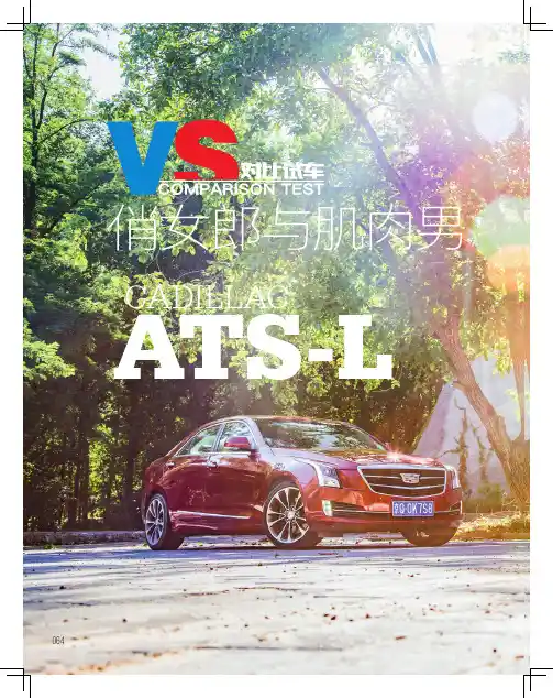
俏女郎与肌肉男CadillaC ATS-L064065文:李文斌 图:袁晓晔 事实上,它们相遇纯属偶然,本来只预定了阿尔法·罗密欧Giulia 一款车,不曾想第二天主编开来了凯迪拉克ATS-L。
虽然两车性格迥异,但却是天作之合,既然聚到一起,那就是缘分。
alfa RomeogiuLiA 我猜想绝大多数人应该都会对阿尔法·罗密欧Giulia 更加心存好感,原因很简单,意大利人在设计方面的造诣简直令人发指。
Giulia 全身充满了曼妙的线条,没有一丝多余。
尽管时代不断变化,但阿尔法·罗密欧始终坚持极富家族特色的三叶草形前脸设计。
炯炯有神的“眯缝眼”车灯好似在坏笑,但又略带有几分杀气。
独特的侧牌照架位置可以最大程度保持前脸的美感。
CadillaCATS-L067 不过阿尔法·罗密欧何许车也,法拉利的员工曾经半开玩笑地说过阿尔法·罗密欧就是可以日常开的法拉利。
这足以看出阿尔法·罗密欧的性能有多出色。
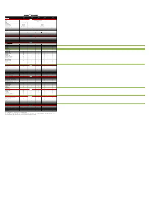
作为Giulia中的入门车型,这台低功CadillaCATS-L 068022凯迪拉克ATS-L 28T领先型车辆规格长、宽、高/mm 轴距/mm 整备质量/kg 最小离地间隙/mm 行李厢容积/ L 动力系统发动机型式L4、涡轮增压4 730、1 824、1 4292 8601 600118-大扭矩,看上去非常令人兴奋。
更令人感到意外的是,ATS-L 居然搭载了一台由通用集团研发,代号为8L45的8挡自动变速器。
全新的变速器无论是换挡平顺性还是燃油经济性较之前的6挡自动变速器来说都有了明显的进步,不过与发动机的默契度还有待提升。
070 同样,虽然轴距经过加长,但凯迪拉克ATS-L依然有着丰富的运动细胞。
前麦弗逊式、后五连杆式独立悬架有着不错的基础,并且还配备了MRC主动电磁感应减振器。
这套主动电磁感应减振器号称是阿尔法·罗密欧Giulia车辆规格长、宽、高/mm 轴距/mm 整备质量/kg 最小离地间隙/mm 4 643、1 860、1 4362 820--符合运动型车的风格。
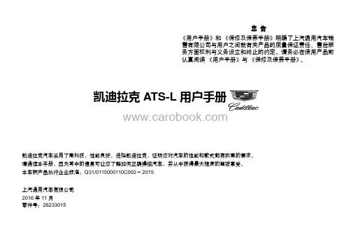
忠告《用户手册》和《保修及保养手册》明确了上汽通用汽车销售有限公司与用户之间就有关产品的质量保证责任、售后服务方面权利与义务设立和终止的约定。
请务必在使用产品前认真阅读《用户手册》与《保修及保养手册》。
凯迪拉克ATS-L凯迪拉克汽车采用了高科技,性能良好。
选择凯迪拉克,证明您对汽车的性能和款式都有极高的要求。
请通读本手册,因为其中的信息可让您了解如何正确操控汽车,并从中获得最大程度的驾驶享受。
本车辆产品执行企业标准:Q31/0115000110C002-2015上汽通用汽车有限公司2016年11月零件号:26233015凯迪拉克ATS-L用户手册目录引言....................................................................0-1钥匙、车门和车窗........................................................1-1座椅和保护装置..........................................................2-1储物....................................................................3-1仪表和控制装置..........................................................4-1照明....................................................................5-1信息娱乐系统............................................................6-1温度控制装置............................................................7-1驾驶和操作..............................................................8-1车辆养护................................................................9-1技术数据...............................................................10-1引言0-1引言引言.....................................0-2引言..................................0-2使用本手册.........................0-2警告、告诫和注意................0-20-2引言引言引言本车的设计集先进技术、安全、环保和经济性于一体。

ATS-1音频分析仪操作手册操作方法概述: 对比度旋钮操作方法概述前面板控制器可分为以下各部分:图4-1前面板按键组成CONTRAST对比度旋钮对比度旋钮用于调整亮度及液晶显示器的视角。
如果观看屏幕时有困难,调整此旋钮能够使显示字符和背景较容易地区分开来。
屏幕亦可反转为背景黑而字符光来显示,该项调整放在设置面板中。
参见页4-8。
仪器模式键——面板导航仪器模式键选择主要的操作模式和显示模式。
通过这些按键可选择1——7种不同的显示面板。
P1PA用户手册Pg 4-1概述: 仪器模式键——面板导航操作方法下图表示各主面板之间的切换关系:捷径:按任何功能键将进入主面板,甚至测量功能不变。
图4-2 面板导航Pg 4-2 P1PA用户手册操作方法概述: 仪器模式键——面板导航本机一开机时,将进入默认的主面板。
其外观如下:图4-3 选择主面板顶部一行的是分析区,通常显示为一、二、或三个实时的读数。
中间一行是信号发生器区,用于显示信号发生器的运行参数。
底部一行提供给软键使用,用于在不同的仪器条件下改变相应的功能。
面板按键提供主面板、和发生器面板、分析器面板和设置面板。
通常第一次按下面按键进入主面板,随后按下该键会在上述面板中循环,最后并返回主面板。
按下BARGRAPH键进入条形面板,其外观如下:图4-4 条形面板这个面板的三个实时的读数,顶部一行如同主面板顶部。
底部替换为一个水平的条形,条形能实时显示读数。
有关更多条形的内容请参见页4-57。
P1PA用户手册Pg 4-3概述: 仪器模式键——面板导航操作方法按SWEEP键可进入扫描面板,其外观如下:图4-5 扫描面板扫描面板用于测量一定范围内的频率或幅度的每一步的值,并读取每步读数。
并根据读数在画面显示图形。
读数产生在垂直轴。
详情参见页4-59。
PRINT键的操作取决于当前屏幕显示的不同而有不同的操作。
当扫描面板显示完毕后按下PRINT键,显示屏将会切换到打印面板,其外观如下:图4-6 打印面板或者表格数据。

适用车型:凯迪拉克ATS-L/XTS/XT4/XT5/CT6零件名称:全新一代流媒体后视镜热线电话:400-820-1902感谢您选择和使用我司生产的全新一代流媒体后视镜产品,相信本产品能为您带来全新的驾乘体验。
如您在使用本产品过程中有任何疑问,请及时与我们取得联系。
本手册旨在为用户提供一个使用此全新一代流媒体后视镜的信息指引,在使用本产品前请仔细阅读此手册,并请妥善保存以备将来使用!特别声明1.本手册所显示的产品外观可能与实物存在差异,请以实物为准。
2.本手册使用的画面示例可能与实际画面有所不同,请以实际画面为准。
3.本手册仅作为用户操作指南,不作为维修服务依据。
产品升级和更新或相关参数变化,恕不另行通知,敬请谅解!4.本手册版权归本公司所有,未经许可,任何单位或个人不得将本手册之部分或全部内容用于商业用途。
5.本手册包括截止至该手册印刷时为最新信息。
上汽通用汽车有限公司负责该手册的修订及说明,并保留该手册印刷后更改而不另行通知的权利。
本手册中部分示意图仅供参考,若图片与实物不符,以实物为准。
6.本公司拥有本手册的最终解释权。
安全提示为保证您和您的汽车及他人的安全,请您务必做到以下一些基本要求:1.行车中请勿操作内后视镜。
2.影像有盲区,变道或转弯时请观察外后视镜。
警告:全新一代流媒体后视镜的视野有限。
可能看不见一部分道路、车辆和其他物体。
行驶或泊车时,请勿只使用此摄像头。
物体的显示距离可能比实际距离更近。
变换或并入车道时,请检查车外后视镜或者转头扫视一下。
不够小心可能导致伤害、死亡或车辆损坏。
注意事项:1.本产品不包含SD卡,用户需自行购买SD卡方可使用(支持8G~128G C10 以上的品牌高速SD卡,建议历时6个月更换一次新卡)。
2.本产品不支持Micro SD卡。
3.请在车辆断电熄火后正常插拔卡。
4.请勿自行对流媒体后视镜进行拆装,如有需要请致电400咨询电话或至4S店进行相关操作。
一、特别说明 (2)二、内后视镜面板功能 (4)三、MyCadillac APP功能说明 (5)3.1扫码绑定 (5)3.1.1 下载MyCadillac APP (5)3.1.2 绑定步骤说明 (5)3.2MyCadillac APP功能说明 (7)四、实时自检 (8)4.1屏幕显示关闭 (8)4.2屏幕显示开启 (9)4.2.1 停车实时自检 (9)4.2.2 行车实时自检 (11)五、屏幕显示关闭操作 (13)5.1锁存/终止锁存 (13)5.2屏幕显示开关 (13)六、屏幕显示开启操作 (14)6.1停车时操作 (14)6.1.1 锁存/终止锁存 (14)6.1.2 亮度调节 (14)6.1.3 角度调节 (14)6.1.4 回放 (15)6.1.4.1 回放列表 (15)6.1.4.2 回放中 (16)6.1.5 系统设置 (17)6.2行车时操作 (18)6.2.1 锁存/终止锁存 (18)6.2.2 亮度调节 (18)6.2.3 角度调节 (18)6.2.4 提示停车操作 (19)附录1故障排除 (20)附录2 有害物质声明 (21)附录3 保修服务 (22)一、特别说明1.说明书中有用矩形图片表示,图像显示实际是在异形框内。
永不冷却的糖衣炮弹车主详说上海通用凯迪拉克ATS
张宇翔
【期刊名称】《车主之友》
【年(卷),期】2014(000)008
【摘要】凯迪拉克这家老字号,正在用ATS为车主们全新打造一条出行的快车道。
不容置疑的是,对凯迪拉克ATS的翘首企盼,是完全必要而有价值的。
细节
1.完美的机械结构是凯迪拉克的传统强项,它所带来的出色行驶品质一向为人称道——在动力方面,ATS更是展开了“大酬宾”。
2.0T涡轮增压直喷发动机竟然
给出了203kW的最大功率和353N·m的最大扭矩,配合6档手/自一体变速器,性能实在有些势不可挡。
【总页数】4页(P192-195)
【作者】张宇翔
【作者单位】不详
【正文语种】中文
【中图分类】U469.11
【相关文献】
1.功能强大质量细节需提升上海通用凯迪拉克XTS车主调查分析报告
2.从修辞学
的角度分析丘吉尔的演说辞——以《永不屈服,永不,永不,永不》为例3.丘吉尔演说的修辞艺术分析——以《永不屈服,永不,永不,永不》为例4.上海通用凯迪拉克
ATS轿车车身控制单元的编程5.加长是硬道理——上海通用凯迪拉克ATS-L
因版权原因,仅展示原文概要,查看原文内容请购买。
Holding CabinetFL-2371-LCRev. 3 (5/14)Page 1 of 95925 Heisley Road • Mentor, OH 44060-1833Cabinet model number:Cabinet serial number: Authorized Service Agency:Ph:Fax:Keep this manual for future reference.OPERATING and MAINTENANCE INSTRUCTIONSModels: H138NPSCLCMC5QRL Merchandising Hot CabinetsHolding Cabinet FL-2371-LCRev. 3 (5/14)Page 2 of 95925 Heisley Road • Mentor, OH 44060-1833ELECTRICAL SPECIFICATIONS:Model No.VoltsWattsAmpsHertzPhaseNEMAH138NPSCLCMC5QRL 120200016.6601L5-20PINSTALLATION & OPERATION INSTRUCTIONSINSTALLATION:1. Remove all paper and packing material from inside of cabinet.2. Remove protective paper and vinyl material from outside surfaces of cabinet.3. For shelf installation, see page 8.4. Place the cabinet in a well-ventilated area.5. Place cabinet on level floor.6. Plug cord end into proper wall outlet.7. See page 4 to reverse the door openings.FIRST TIME START-UP:1. Push the POWER switch to “ON”, and run the unit for one hour.NOTE: DO NOT PUT FOOD INTO CABINET!This step is to burn off manufacturing oils and excess adhesive.2. Let the cabinet cool and wipe inside clean with detergent and hot water before first use.Blower inlet guard must be in place before operating cabinet.HOW TO HOLD:1. Push POWER switch to “ON.” POWER LIGHT will come on.2. The control is preset to maintain an averagetemperature of 160°F. Displayed temperatures will change during loading and unloading of product.3. Preheat cabinet for 45 minutes.4. Put product into cabinet.NOTE: Proper food holding temperature is140°F/60°C or higher.Air is VERY HOTwhen door is opened.Holding CabinetFL-2371-LCRev. 3 (5/14)Page 3 of 95925 Heisley Road • Mentor, OH 44060-1833BEFORE cleaning the cabinet:1. Unplug the cabinet from the wall.2. Allow cabinet to cool.1. Do NOT use abrasives (steel wool) or harshchemicals (chlorine, bromine, iodine or ammonia).2. Do NOT use a water sprayer (pressure sprayer) to clean the cabinet.CLEANING HINTS:1. Wipe up spills as soon as possible.2. Clean cabinet daily to avoid heavy dirt build-up.3. Make a test spot with cleaner:a) Follow manufacturer’s directions on cleaner.b) Do not mix cleaners.c) Avoid drips and splashes.HOW TO CLEAN WIRE RACKS:1. Remove all items from shelves.2. Place towels under the area you will be cleaning.3. Spray shelves with a degreasing cleaner and wait two minutes.4. Scrub the shelves with a brush. Use a toothbrush to get between the wires.5. Wipe off with a damp sponge and warm water. Dry with towels.HOW TO CLEAN THE UNIT:SoilCleanerMethodCABINET Inside and Outside (Stainless Steel)DAILY CLEANINGMild detergent and hot water.1. Sponge on with cloth.2. Rinse with water.3. Wipe dry.STUBBORN SPOTS ANDSTAINSMild abrasive made for stainless steel.1. Apply with damp sponge or cloth.2. Rub lightly.3. Rinse with water and wipe dry.BURNT-ON FOODS OR GREASEChemical oven cleaner for stainless steel.Follow oven cleaner manufacturer’s directions.HARD WATER SPOTS and SCALEVinegar1. Swab or wipe with cloth.2. Rinse and dry.*Mild detergents include soaps and non-abrasive cleaners.Note: Gaskets are removable for cleaning.MAINTENANCE INSTRUCTIONSHOW TO REVERSE THE DOOR OPENING: 1. Open the door 180°, lift it up and off. Lay it downwith the outside up.2. Pop off the hinge covers with a regularscrewdriver.3. Unscrew the hinges and pull handle and remountthem to the opposite sides of the door (make sure the hinge pin is down).4. Remove the cabinet hinges with door stopbrackets. Remove the screws plugging the mating hinge holes on the opposite side of the cabinet. 5. Lift out and turn the plastic cam in each cabinethinge 180°. Use a screwdriver to pop them out,if necessary (see Figure 1). Mount the hingesand door stop brackets onto the opposite side ofcabinet (see Figure 2).6. Put the door back onto the cabinet and adjust/tighten the hinges as shown on page 5.MAINTENANCE INSTRUCTIONSFigure 1Right Hand Hinge (as shipped)Note the position of curved dwell on the cam afterturning it 180°Figure 2Left Hand HingeHow to adjust/tighten the double door hinges:1. Open the door 180°, lift it up and off. Lay it down with the outside up.2. Pop off hinge covers with a screwdriver.3. Loosen the screws that hold hinges to the door. Those holes are slotted for adjustment.a) Push the hinge back for the door to close easier; or b) Pull the hinge forward to close the gap between the door and the cabinet.4. Tighten the screws and then test the door.How to adjust /tighten the full door hinges:1. Loosen the screws holding the hinge to the door.2. Push or pull the hinge per instructions above.MAINTENANCE INSTRUCTIONS TROUBLE-SHOOTING GUIDEHINGE COVERFAILUREPOSSIBLE CAUSE1. POWER LIGHT (Yellow) does NOT light.1a. Switch is “OFF”.1b. Cord unplugged from wall outlet.1c. Circuit breaker/fuse to wall outlet tripped/blown.2. Unit does not heat.2a. Temperature control is set too low.2b. Switch is “OFF”.3. Unit gets too hot or won’t shut off.3a. Defective electrical parts.UNPLUG UNIT FROM WALL OUTLET.4. Blower does not work or makes noise.4a. Defective blower.5. GFCI device trips.5a. The insulation inside the heating element may have absorbed some moisture. This may have occurred if the cabinet has not been used for a long period of time or during shipping and storage of the cabinet. Plug the cabinet into a non-GFCI outlet and set the temperature control to its maximum. Let the cabinet run for about 1 hour to dry out the heating element from any moisture may have been absorbed. If the circuit breaker trips, call the factory Authorized service agent. After drying the heating element, plug cabinet into the GFCI receptacle; the cabinet should run properly. If the GFCI device continues to trip, call the factory Authorized service agent.GFCI (ground-fault circuit interrupter): A GFCI receptacle is a device that de-energizes a circuit when it detects an unsafe flow of current to ground. The intention of a GFCI device is to minimize the potential for an electrical shock.If cause is none of the above, refer to our list of Authorized Service Centers, FL-1400Holding CabinetFL-2371-LCRev. 3 (5/14)Page 6 of 95925 Heisley Road • Mentor, OH 44060-1833REPLACEMENT PARTSInclude all information on nameplate when ordering partsITEM DESCRIPTION120V1Blower Kit0769-180-K-LC 2Heater Kit, Air 1850 Watt 0811-022-K 3High Limit 0848-0604Power Switch 0808-116-K 5Power Light0766-094Relay - Solid State (not shown)0857-1347Temperature controller0848-075-LCK 8Transformer (used with Temp controller)0769-1599Terminal Block (4 pole)0852-093Terminal Block (2 pole)0852-09110Vent Fan0769-165Power Cord (not shown)20 Amp 0810-065-14-LK11Fan Guard 0769-16712Cord Bracket 0553-75713Strain Relief 90°0818-095Holding Cabinet FL-2371-LCRev. 3 (5/14)Page 7 of 95925 Heisley Road • Mentor, OH 44060-1833REPLACEMENT PARTSInclude all information on nameplate when ordering partsCABINET REPLACEMENT PARTS:ItemDescription Part No.ItemDescriptionPart No.1Caster0569-306-K 10Door, front, solid 1221-534-LCK 2Caster with brake 0569-306-BK 11Door, back, window 1221-629-LCK 3Gasket, front doors 0861-245-K 12Handle, door0911-115-LCK 4Gasket, back door 0861-246-K 13Hinge Kit, lift off, set of 20519-114-LCK 5Wire shelf1170-00514Hinge, butt type 0519-089-K Display Rack (upper)See Page 815Air tunnel0546-1206Rack insert (lower)1170-213-LCK 16Light Display, Complete 0820-0588Wire blower inlet guard 1170-21117Light Bulb Kit, set of 50820-059-019Door, front, window1221-616-LCKHolding CabinetFL-2371-LCRev. 3 (5/14)Page 8 of 95925 Heisley Road • Mentor, OH 44060-1833DISPLAY RACK INSTALLATION (Recommended)Front 4th Hook6th HookBottomDISPLAY RACK REPLACEMENT PARTS Item DescriptionPart No.1Post, Left 1170-2392Post, Right1170-2403Post, Right Rear 1170-2374Post, Left Rear 1170-2385Wire Shelf 1170-2236Wire Shelf 1170-236HALOGEN BULB REPLACEMENT INSTRUCTIONS:1. Turn PWR switch OFF, UNPLUG unit from wall outlet and allow unit to COOL to prevent SHOCK or BURN.2. Insert small screwdriver between lens and mounting screwat a 45 degree angle and apply pressure while pulling down the lens. DO NOT DROP GLASS LENS!3. Pull bulb STRAIGHT out. If necessary, gently pry at the base of bulb using a wiggling motion.NOTE: For longest bulb life, do NOT handle a new bulb with bare hands. Use clean glove or cloth to install.Holding CabinetFL-2371-LCRev. 3 (5/14)Page 9 of 95925 Heisley Road • Mentor, OH 44060-1833WIRING DIAGRAM*F O R T W I S T L O C K O P T I O NBLACKWHITET E M P E R A T U R E C O N T R O LW A CA C N OBC t °T R A N S F O R M E R 110V /220432815B L O W E R M O T O RV E N T F A NV E N T F A N B L O W E R M O T O R5-20P 120V , 20A O R L 5-20P *WHITEBLACKGH I G H L I M I TH E A T E R A I R5-15P 120V , 15A O R L 5-15P *G10594S O L I D S T A T E R E L A YL1 T1A2 A1H I G H L I M I TP W R S W I T C H112210121314131415162526152512162697820192265378193204F R O N T L IGH T FI X T U R E SR E A R L I G H T F I X T U R E SM C C A B I N E T O N L Y。
ATS100 (With GPS) Intelligent Turn Assist System User ManualAutel Intelligent Automobile Co., Ltd.TrademarksAutel®, MaxiSys TM, MaxiDAS®, MaxiScan®, MaxiTPMS®, MaxiVideo TM, MaxiRecorder TM, and MaxiCheck TM are trademarks of Autel Intelligent Technology Corp., Ltd., registered in China, the United States, and other countries. All other marks are trademarks or registered trademarks of their respective holders.Copyright InformationNo part of this manual may be reproduced, stored in a retrieval system, or transmitted in any form or by any means, electronic, mechanical, photocopying, recording, or otherwise without the prior written permission of Autel Intelligent Automobile Co., Ltd.Disclaimer of Warranties and Limitation of LiabilitiesAll information, specifications and illustrations in this manual are based on the latest information available at the time of printing.Autel Intelligent Automobile Co., Ltd. will not be liable for any direct, special, incidental, or indirect damages, or for any economic consequential damages (including lost profits) as a result of using the product.IMPORTANTBefore operating or maintaining this unit, please read this manual carefully, paying extra attention to the safety warnings and precautions.For Services and SupportWeb: Email: *********************Hotline: 0086-755-2267-2493 (China HQ) / 1-855-AUTEL-US (288-3587) (North America) / 0049 (0) 6103-2000520 (Europe) /+045 5948465 (APAC) / +971 585 002709 (IMEA)For technical assistance in all other markets, please contact your local distributor.This product holds the approval of German ABE for Abbiegeassistent. Any modifications to the product will result to an automatic cancelation of this approval. The user is also obliged to observe the product in accordance to it’s legal requirement.Table of Contents1.ATS100 Turn Assist System Introduction (1)1.1ASR100 Radar Introduction (2)1.2Warning Display (3)1.3GPS&IMU Module (6)1.4System Connections & Wire Harness Description (7)er Guide (10)2.1 Radar Installation (10)2.2 Radar Wiring (13)2.3 Input Signal Access (14)2.4 Power Access (15)2.5 GPS&IMU Module Installation (15)2.6 Display Screen Installation (16)1.ATS100 Turn Assist System IntroductionATS100 is a turn assist system with accurate target detection and warnings for vehicle blind spots. The system components are as followes: a millimeter-wave radar with operation frequency 76-77GHz and max RF output power 12dbm, a spirit level, a mounting bracket (optional), a warning screen, a GPS&IMU module and the cable. The millimeter-wave radar can accurately measure the target distance, speed, angle, and other information through the difference in echoes between the transmitting and receiving electromagnetic waves. It is an all-weather and all-day operational turn assist system with working temperature from -40℃-85℃. The warning screen warns the driver of a dangerous target in the blind spot and reminds the driver to make timely adjustments to the driving trajectory, to avoid accidents.The ATS100 turn assist system covers 180° on one side, ensuring no blind spots, with target detection range up to 80 x 4.5 m. With a compact structure, it comes with collision pre-determination and graded alarm function, can integrate with external CAN (Controller Area Network) and CAN FD (Flexible Data) interfaces, and supports 12 V or 24 V supply voltage.Figure 1-1 ASR100 radar coverageWarning targets of ATS100 turn assist system include:∙Dynamic vulnerable road users, moving at speeds greater than 3 km/h, including pedestrians, bicycles, electric bicycles, etc.∙Dynamic cars, moving at speeds greater than 10 km/h.Note: The safe use distance of the system needs to be greater than 4cm.1.1ASR100 Radar IntroductionThe ASR100 77 GHz Millimeter-Wave Radar is a compact, rugged radar sensor designed and manufactured by Autel Intelligence Vehicle® in China for side blind zone warnings for heavy trucks/buses, etc. The ASR100 meets automotive grade standard for professional commercial vehicles and has an IP69K rating, in line with the commercial vehicle use environment.Figure 1-2 ASR100 dimensions1.2Warning DisplayThe ATS100 turn assist system employs a precision sensing system to predict future collision probability with the target and provides users with dynamic sensing and display-based intelligent warnings, to remind drivers to take preventative measures in time to reduce the possibility of accidents. The warning display screen supports adaptive brightness control, enabling the screen’s brightness to adjust based on the brightness of the surrounding environment, thereby reducing eye-fatigue for drivers during the night.Figure 1-3 Display sizeThe warning function is divided into three levels as follows: (Note: Prerequisites for enabling the warning function: the speed of the vehicle is <30km/h)●Level 1 warning: The steering wheel angle is less than 30°, , and the target entersthe warning range, then a section of warning light LEDs, displayed in Figure 1-4, light up.●Level 2 warning: The vehicle is turning to the right, the steering wheel angle isgreater than 30° or turn on the turn signal (when the turn signal is connected), and it is expected that the vehicle and the target will collide within a certain amount of time, then a section of warning light LEDs start flashing.●Level 3 warning: The vehicle is turning to the right, the steering wheel angle isgreater than 30° or turn on the turn signal (when the turn signal is connected), and the vehicle and the target collision is imminent within a short amount of time, then the warning light will start flashing and a warning sound is generated.The driver can get the approximate location of the target based on the section of warning light LEDs that are on or are flashing.The detailed description of each warning light on the display is as follows:Figure 1-4 Description of warning light①Warning module power and status indicator: lights up when the status of the warning module is normal.②Brake indicator: This light flashes when actively braking. (Currently this function is not available).③GPS fault indicator: on when GPS sensor has no signal (temporary), flashing when GPS sensor has faulty signal.④Warning light: provides early warning of dangerous targets. The warning area is divided into three different priorities: Zone top (2-5 m in front of the front of the vehicle), Zone central (2 m in front of the front of the vehicle- 7 m behind the front of the vehicle), and Zone bottom (7-30 m behind the front of the vehicle), If there are multiple targets in Zone top, central or bottom at the same time, give priority to Zone central, then Zone bottom, and then Zone top.⑤Vehicle model: for reference; is in a steady on state after power on.⑥Radar status indicator: steady on state indicates a temporary radar failure, usually caused by factors such as radar being blocked, bad weather conditions; flashing indicates a permanent radar failure, requiring professional repair.⑦System fault indicator: The indicator light is on when there is a fault in the entire system.1.3GPS&IMU ModuleThis module integrates high-precision gyroscope, accelerometer, GPS module, adopts high-performance microprocessor and advanced dynamic solution and Kalman dynamic filter algorithm, which can quickly solve the current real-time motion attitude of the module. Using advanced digital filtering technology can effectively reduce measurement noise and improve measurement accuracy. The module integrates an attitude solver and cooperates with the dynamic Kalman filter algorithm to accurately output the current attitude of the module in a dynamic environment. The attitude measurement accuracy is 0.05 degrees static and 0.1 degrees dynamic, with extremely high stability and performance even better than some professional inclinometer.1.4System Connections & Wire Harness DescriptionConnect each port of the radar, display, GPS&IMU module wiring harness as shown below.Figure 1-5 System connections diagramRadar Harness DescriptionIn the figure below, the P1 connector is connected to the radar; it has 8 pins and the pin order is shown as below. The pin number in the figure corresponds to the pin definition in Table 1-2. The P2 connector is connected to the GPS&IMU module; it has 8 pins, and the pin number of P2 in the figure corresponds to the pin definition in Table 1-3. The P3 connector is connected to the vehicle and power supply, it has 6 pins, and the pin number of P3 in the figure corresponds to the pin definition in Table 1-4. The end of each cable has a printed label. Please check it carefully during installation. Do not turn the power on if the connectors are improperly connected.Figure 1-6 Radar wiring harness diagramRadar interface P1 definition table:GPS interface P2 definition table:Vehicle power interface P3 definition table:Display Harness DescriptionIn the figure below, the left P4 connector of the display harness is connected to the GPS module; it has 8 pins and the pin order is shown as below. The pin number in the figure corresponds to the pin definition in Table 1-5.Figure 1-7 Dispaly wiring harness diagramGPS interface P4 definition table:Table 1-5 Definition of GPS interface P4er Guide2.1 Radar InstallationNotes on Installation∙The radar should be installed on a component with little vibration. Strong vibration will negatively affect its detection function.∙The radar should be installed on the most protruding plane on the side of the truck to prevent it from being blocked by other parts and its detection performance from being compromised.Installation position: The radar should be installed on the right side of the truck. For right rudder country please install on the left side of the truck. We recommend you install it on the side guard plate, side guard rail of the truck.Figure 2-1 Radar installation position diagramInstallation range:When the radar is used, the reference coordinate origin is the center of the rear axle of the vehicle. The default installation position parameters of the radar are shown in Table 2-1 which only suitable for vehicles with a wheelbase of about 3.5-5m.Lateral distance X: the longitudinal distance of the radar installation position relative to the center of the rear axle of the vehicle;Longitudinal distance Y: The lateral distance of the radar installation position relative to the center of the rear axle of the vehicle;Installation angle: the rotation angle of the radar installation position relative to the center of the rear axle of the vehicle;Warn_dx: the distance from the center of the rear axle to the front edge of the vehicle.Trailer lengthFigure 2-2 Radar installation location calibration parameters diagramRecommended sensor location is shown in Figure 2-2 below. The radar can be installed at a distance of 230-430cm back from the front edge of the vehicle and a height of 30-120cm from the ground.Figure 2-3 Recommended installation location diagramIf your vehicle’s wheelbase is not within 3.5-5 meters, using the above default radar installation position parameters will cause excessive errors. At this time, the user needs to measure the distance between the actual installation position of the radar and the center of the rear axle of the vehicle to calibrate the installation position of the radar. For the calibration of the radar installation position, please use our customer's host computer AutelRadarCfgTools. The operation steps are shown in Figure 2-4 below:(1) Click the Open button to open the CAN device;(2) Click the Close button to close the CAN device;(3) Select the baud rate of channel 2, the current default value is 250K(4) Click the Start button to open channel 2;(5) Click the Stop button to close channel 2;(6) Select whether the Install Position is facing the left or right side of the front of the vehicle;(7) Enter dx, dy, theta and warn_dx values.dx: the longitudinal distance of the radar installation position relative to the center of the rear axle of the vehicle. Unit: meter;dy: The lateral distance of the radar installation position relative to the center of the rear axle of the vehicle, generally 1.25 m.Installation angle: the left side is -90°, right side is 90°Warn_dx: the distance from the center of the rear axle to the front edge of the vehicle. Unit: meter.Figure 2-4 AutelRadarCfgTools Interface IconInstallation deviations: To ensure detection accuracy, the radar installation horizontal angle error should be at best within ±1°. Installation vertical angle error should be t best within 2°.Figure 2-5 Radar installation deviations diagramExample of InstallationIn order to control installation deviations, an optional auxiliary mounting bracket can be used to adjust the direction and angle during installation.1. With the front of the radar (the side with the plastic casing) facing the detection area, fix the radar to the mounting bracket using the screws.2. Place the spirit level in the middle of the upper plane of the radar and adjust the mounting position adjustment screw until the bubble overlaps the ring in the middle.3. Secure the mounting position adjustment screw, and then connect the cable.Figure 2-6 Radar installation and calibration diagram2.2 Radar WiringInstallation Vertical Angle 30-120cmAfter the radar cable is connected to the radar, it should be routed into the cab together with the chassis cable, as shown in the image below.The entry for the chassis cable into the cab is at the bottom of the cab. Therefore, you need to lift the cab during wiring, as shown in the image below.In front of the front passenger seat (where the main fuse and the main ECU are located), connect the power supply, the display screen and the other parts of this product, as shown in the image below.2.3 Input Signal AccessThe Autel ATS100 requires the 5 interior signals below for its normal operation. The radar automatically reads these CAN J1939 signals by default, The baud rate is 250KB:1.Vehicle speed2.Steering wheel angle3.Yaw rate4.Longitudinal acceleration2.4 Power AccessThe radar has to be powered via KL15 or Clamp 15 (24V). We recommend you find KL15 on the main fuse board and connect the radar to it.2.5 GPS&IMU module InstallationThe GPS/IMU Module can be placed anywhere inside the driver cabin, the preferred position is behind the windshield glass and somewhere in the middle of cockpit.a. Place the GPS&IMU module horizontally, and note that the X-axis direction is consistent with the vehicle's forward direction.b. The module can be fixed using screws or double-sided tape.c. Connect the two wire harnesses at the end of the GPS&IMU module to the radar and display respectively.Note: GPS&IMU module installation angle tolerance<30°2.6 Display Screen Installationa. Remove the A-pillar cover and drill holes: Referring to Figure 1, take the mounting holes on the bracket back plate as reference points, and drill two 4.5 mm mounting holes and one 12 mm hole to route the cable through (30-40 mm below the mounting holes).b. Referring to Figure 2, use two M4*14 screws to fix the bracket back plate to the A-pillar cover.Note: 3M adhesive on the bracket back plate allows the bracket to be stuck on the A-pillar cover.c. Referring to Figure 3, route the cable on the screen assembly through the cable hole on the A-pillar cover.d. Referring to Figure 4, place the screen assembly on the corresponding position on the bracket back plate, as shown in view V and view VI. You can rotate the screen around the axis to adjust its angle, and then fix the screen assembly with M4*14 screws.e. Install the cover back to the A-pillar.17。
1 LX shown in Starfire Pearl // Options shown.3LX shown in Silver Lining Metallic // Options shown.2DO EVERYTHING YOU CAN IMAGINE.AND A FEW MORE THINGS THAT YOU CAN’T. THE UNPARALLELED 2014 LX.4LX shown in Nebula Gray Pearl // Options shown.56LX shown in Parchment leather with Mahogany wood trim // Options shown.7EXCEPTIONALL8LX shown in Silver Lining Metallic // Options shown.910LX shown in Parchment leather with Mahogany wood trim // Options shown.11LX shown in Silver Lining Metallic // Options shown.13The available Wide-view Front Monitor 16 captures a broad view of the forward and peripheral surroundings, which then displays on the Navigation15403 lb-ftt orque @ 3,600 rpm 1290% of maximum torqueavailable @ 2,200 rpm7,000-poundt owing capacity 13,14G. Available Wide-view Front and Side Monitor system 4 H. Blackleather interior with Mahogany trim I. Available Rear-SeatEntertainment System (RSES ) J. Electroluminescent instrumentation with multi-information display K. Steering-wheel controls L. USB connectivity1716 A. Transfer case, Crawl Control,11 vehicle height andsuspension controls B. Parchment leather interior with Mahogany trim C. Power open/close rear door D. Subscription-free Lexus Enform App Suite 7 E. Versatile rear seating F. Three-row, eight-passenger seating20Four-zone automatic climate control with smog sensor and automatic circulation mode // Lexus Memory System // Power tilt-and-slide moonroof // Power rear door // Leather-trimmed interior // Mahogany interior trim // 10-airbag system 20 // Navigation System 17 // Lexus Enform 7 one-year trial subscription // Lexus Enform App Suite 7 // Full-timefour-wheel drive // Adaptive Variable Suspension (AVS ) with Active Height Control (X-AHC ) // Crawl Control 11 with T urn Assist // 14-way driver’s seat(including dual-function lumbar and cushion extender ) // Power-sliding,60/40-split middle-row seatwith 40/20/40-split seatback // Auto on/off High-Intensity Discharge (HID ) headlamps with Dual-swivel Adaptive Front Lighting System (AFS )21 // Wood- and leather-trimmed steering wheel and shift knob // Smart Stop technology 22 // T railer Sway Control 1820-in split-five-spoke alloy wheels 27 STANDARDKEYSTANDARD FEATURESPACKAGES WHEELS For complete list, visit /LX/featuresINDIVIDUAL OPTIONSMark Levinson 19-speaker 450-watt @ less than0.1% THD, 20–20,000 Hz 23 Reference Surround Sound Audio System 1 // Heated and ventilated front seats and heated second-row seats // Dual-screen DVD Rear-Seat Entertainment System (RSES )9 // Wide-view Front and Side Monitor system 4 with Intuitive Parking Assist // Pre-Collision System (PCS )15 and Dynamic Radar Cruise Control 24For complete list, visit /LX/options For complete list, visit /LX/packagesFor complete list of Genuine Lexus Accessories, visit /LX/accessoriesLUXURY PACKAGE WITH PRE-COLLISION SYSTEM AND DYNAMIC RADAR CRUISE CONTROLSemi-aniline leather-trimmed interior with contrast stitching // Heated steering wheel // Heated and ventilated front seats // Heated second-row seats // Mahogany-trimmed door switchplates and rear-center armrest cover // Front-seat cool box // SmartAccess 25,26 cardkeyLX shown in Silver Lining Metallic // Options shown.21HEIGHT 75.6 INKEY SPECS5.7L V87.5S12,28LX 570ENGINEPERFORMANCE12 / 17 / 1429FUEL ECONOMY, EPA-ESTIMATED RATINGS (CITY / HIGHWAY / COMBINED ) 4W D6-SPEEDSTANDARDDRIVETRAINSEQUENTIAL-SHIFT ELECTRONICALLY CONTROLLED TRANSMISSIONEST MPG0–60 INFor complete specs, visit /LX/specsWIDTH 77.6 INOVERALL LENGTH 197.0 INWHEELBASE 112.2 INHORSEPOWER383HP12TORQUE GROUND CLEARANCECARGO CAPACITY (MAX )TOWING CAPACITY403LB-FT 128.9IN83.1CU FT 57,000LB 13,1423EXTERIORSILVER LINING METALLIC STARFIRE PEARL NEBULA GRAY PEARLSATIN CASHMERE METALLICCLARET MICABLACK ONYX22INTERIOR BLACKLEATHERPARCHMENTLEATHERTRIMMAHOGANYFPOFSC Logo—, NOVEMBER 14, 2012“THE BIGGEST, MOST CAPABLE AND MOST OPULENT SPORT-UTILITY ON THE BLOCK.”WARRANTY Four-year/50,000-mile Lexus Limited Warranty. Six-year/70,000-mile Powertrain Warranty. Six-year/unlimited-mileage Corrosion Perforation Warranty. All warranties with zero deductible. See the LX Warranty and Services Guide at your Lexus dealer for details. DISCLOSURES 1. Mark Levinson ® is a registered trademark of Harman International Industries, Inc. 2. The LX 570 is designed to meet most off-road driving requirements. Abusive use may result in bodily harm or damage. Lexus encourages responsible operation to help protect you, your vehicle and the environment. Seatbelts should be worn at all times. Please do not allow passengers to ride in the cargo area. Tow hitch receivers/ball mount kits are not intended to provide crash protection. 3. The backup camera does not provide a comprehensive view of the rear area of the vehicle. Y ou should also look around outside your vehicle and use your mirrors to confirm rearward clearance. Cold weather may limit effectiveness and view may become cloudy. 4. The Wide-view Front and Side Monitor does not provide a comprehensive view of the front and side areas of the vehicle. Y ou should also look around outside your vehicle and use your mirrors to confirm clearance. Cold weather will limit effectiveness and view may become cloudy. 5. The Wide-view Side Monitor system does not provide a comprehensive view of the front passenger-side area of the vehicle. Y ou should also look around outside your vehicle and use your mirrors to confirm clearance. Cold weather will limit effectiveness and view may become cloudy. 6. Cargo and load capacity limited by weight and distribution. 7. Always drive safely, obey traffic laws & focus on the road while driving. Apps/services vary by phone/carrier; functionality depends on many factors. Select apps use large amounts of data, you are responsible for all charges. Apps/services are subject to change. Apps identified by ™ or ® are trademarks or registered trademarks of their respective companies. For enrollment, cost and more details, see /enform. 8. Contact with the response center may not be available in all areas. Service Agreements required. A variety of subscription terms available; charges will vary. See for details. 9. A single-disc DVD player is standard. A separate DVD player or game system utilizing the center console’s video/audio inputs is required in order to use the split-screen function of the dual-screen system. 10. Headphones are for passenger use only. Do not use while operating vehicle. 11. Crawl Control is designed for driving on difficult terrain at low speeds. It assists the driver by controlling acceleration and braking, allowing the driver to focus on steering. The LX 570 is designed to meet off-road driving requirements, but off-roading is inherently dangerous. Always wear seatbelts. 12. Ratings achieved using the required premium unleaded gasoline with an octane rating of 91 or higher. If premium fuel is not used, performance will decrease. 13. Before towing, confirm your vehicle and trailer are compatible, hooked up properly and you have any necessary additional equipment. If gross trailer weight is above 5,000 lb (2,268 kg ), it is necessary to use a weight-distributing hitch with sufficient capacity. Do not exceed any Weight Ratings and follow all instructions and cautions from your trailer-hitch manufacturer and vehicle Owner’s Manual . The maximum amount you can tow depends on the total weight of any cargo, occupants and available equipment. 14. Please consult your Lexus dealer or Owner’s Manual for towing and load specifications. 15. The Pre-Collision System is designed to help reduce the crash speed and damage in certain frontal collisions only. It is not a collision-avoidance system and is not a substitute for safe and attentive driving. System effectiveness depends on many factors, such as speed, driver input and road conditions. See Owner’s Manual for further information. 16. The Wide-view Front Monitor does not provide a comprehensive view of the front area of the vehicle. Y ou should also look around outside your vehicle and use your mirrors to confirm clearance. Cold weather will limit effectiveness and view may become cloudy. 17. Availability and accuracy of the information provided by the Navigation System or any SiriusXM™ and/or HD Radio™ services mentioned (if installed ) are dependent upon many factors. Use common sense when relying on information provided. Services not available in every city or roadway. Periodic Enform app updates do not include Navigation updates. Navigation updates are available at an additional cost from your local dealer. See Navigation Owner’s Manual or contact SiriusXM for details. 18. Trailer Sway Control (TSC ) is an electronic system designed to help the driver maintain vehicle control under adverse conditions. It is not a substitute for safe driving practices. Factors including speed, road conditions and driver steering input can all affect whether TSC will be effective in preventing a loss of control. See Owner’s Manual for details. 19. TORSEN ® is a registered trademark of Zexel Torsen, Inc. 20. All the airbag (AB ) systems are Supplemental Restraint Systems. All ABs are designed to inflate only under certain conditions and in certain types of severe collisions: frontal and knee ABs typically inflate in frontal collisions; side and side curtain ABs in side collisions; Roll-Sensing Curtain ABs at a severe tilt degree, roll or lateral G-force. In all other accidents, the ABs will not inflate. To decrease the risk of injury from an inflating AB, always wear seatbelts, sit upright in the middle of the seat as far back as possible and do not lean against the door. Do not put objects in front of an AB or around the seatback. Do not use a rearward-facing child seat in any front passenger seat. The force of an inflating AB may cause serious injury or death. See Owner’s Manual for further information/warnings. 21. The Adaptive Front Lighting System helps improve vision at night. Situations such as dirty windshield, rapidly changing light conditions or hilly terrain will limit effectiveness, requiring the driver to manually turn off. See Owner’s Manual for details. 22. Smart Stop Technology operates only in the event of certain simultaneous brake and accelerator pedal applications. When engaged, the system will reduce power to help the brakes bring the vehicle to a stop. Factors including speed, road conditions and driver input can all impact stopping distance. Smart Stop T echnology is not a substitute for safe and attentive driving and does not guarantee instant stopping. See Owner’s Manual for further details. 23. Continuous average power, all channels driven, at less than 0.1% THD; 20–20,000 Hz. 24. Dynamic Radar Cruise Control is designed to assist the driver and is not a substitute for safe and attentive driving practices. See Owner’s Manual for details. 25. The SmartAccess system may interfere with some pacemakers or cardiac defibrillators. If you have one of these medical devices, please talk to your doctor to see if you should deactivate this system. 26. The engine immobilizer is a state-of-the-art anti-theft system. When you insert your key into the ignition switch or bring a SmartAccess fob into the vehicle, the key transmits an electronic code to the vehicle. The engine will only start if the code in the transponder chip inside the key/fob matches the code in the vehicle’s immobilizer. Because the transponder chip is embedded in the key/fob, it can be costly to replace. If you lose a key or fob, your Lexus dealer can help. Alternatively, you can find a qualified independent locksmith to perform high-security key services by consulting your local Y ellow Pages or by contacting . 27. 20-in performance tires are expected to experience greater tire wear than conventional tires. Tire life may be substantially less than 20,000 miles, depending upon driving conditions. 28. Performance figures are for comparison only and were obtained with prototype vehicles by professional drivers using special safety equipment and procedures. Do not attempt. 29. 2014 EPA-estimated ratings. Actual mileage will vary.Lexus strives to build vehicles to match customer interest, and thus they typically are built with popular options and option packages. Not all options/packages are available separately, and some may not be available in all regions of the country. See for information about options/packages commonly available in your area. If you would prefer a vehicle without any or with different options, contact your dealer to check for current availability or the possibility of placing a special order. Specifications, features, equipment, technical data, performance figures, options, and color and trim are based upon information available at time of printing, are subject to change without notice, and are for mainland U.S.A. vehicles only. Some vehicles shown with available equipment. See your Lexus dealer for details. Lexus reminds you to wear seatbelts, secure children in rear seat, obey all traffic laws and drive responsibly. For more information, call 800-USA-LEXUS (872-5398) or visit . To learn more about your financing options, contact your Lexus dealer or call Lexus Financial Services at 800-874-7050. P4-021 (XX/13) 00217-LXBRO -14 Printed in U.S.A. (XXXM ) ©2013 Lexus.。