Bosch_CAN用户手册中文版
- 格式:doc
- 大小:1.84 MB
- 文档页数:21

1. C_CAN用户手册1术语和缩写Terms and AbbreviationsThis document uses the following terms and abbreviations.这个文档使用到以下的术语和缩写。
Term MeaningCAN Controller Area Network控制器局域网BSP Bit Stream Processor位流处理器BTL Bit Timing Logic位时间机制CRC Cyclic Redundancy Check Register循环冗余码校验冗余DLC Data Length Code数据长度编码EML Error Management Logic错误管理机制FSM Finite State Machine有限动作状态TTCAN Time Triggered CAN 时间触发通讯的控制器局域网2. C_CAN用户手册2Functional Description功能简介C_CAN是可以作为单独或集成ASIC一部分的CAN总线模块。
用硬件描述语言描述C_CAN综合到逻辑器件。
它包含CAN内核、消息RAM、消息处理状态机、控制寄存器和模块接口。
CAN内核通信符合CAN协议规范2.0A和2.0B。
在使用中位速率可以编程达到1M/S。
硬件连接物理层需在接收发射器。
在CAN网络中通信,每个消息目标需要设定,接收的消息目标和识别符掩码存储到消息RAM中。
所有关于消息处理是在消息处理状态器中完成。
这些功能包括消息过滤、CAN内核与消息RAM之间的通信和消息发送中断请求并产生中断模块。
C_CAN中的寄存器组可以通过接口模块被外器CPU访问。
这些寄存器用于控制或配置CAN内核和消息处理状态机,并存储到消息RAM。
在C_CAN模块中的接口模块可以定制成适合于用户使用的模块接口。
C_CAN具有以下的功能特性:支持CAN协议怎版本2.0A和版本2.0B位速度达到1M/S32个消息目标(在消息RAM中有32个可以自定义接收或发送的消息目标)每个消息目标有自己的识别符掩码可编程的FIFO模式(消息目标在FIFO中连续存放)可屏蔽中断对于时间触发的CAN应用可以取消自动重传模式在自己测试操作可以设计成循环模式(重复发关这一个消息)兼容摩托罗拉公司HC08的8位单处理模块接口对ARM内核有2个16位的接口模式给AMBA ABB总路线3. C_CAN用户手册3模式结构Block DiagramCAN CoreCAN内核CAN协议控制器和接收与发送移位寄存器完成消息的并行或串行转换Message RAM消息RAN存储消息目标和识别符掩码Registers寄存器所有寄存器用于控制和配置C_CAN模块Message Handler消息状态处理机控制数据在CAN内核接收与发送移位寄存器与消息RAM 之间的传送,也在控制和配置寄存器中产生中断Module Interface模块接口到目前为止,C_CAN模块被分成3种不同的接口。

中央控制器(CCU)部分1.激活的话筒(Active Micro’s):中央控制器(CCU)前面板上的“ 激活的话筒(Active Micro’s)” 有“1”、“2”、“4”三个可选项,表示在开会过程中可以同时打开的话筒的数量,在开会过程中根据具体情况可灵活选择;2.话筒控制方式”Operation”:中央控制器(CCU)前面板上的”Operation”表示话筒控制方式,有“Open”、“Override”、“Voice activation”三个可选项,具体意思如下:λ话筒控制方式“Open”:如果该控制方式被选中,会议代表可通过按下代表机上的话筒按键的方式来激活他们的话筒。
同时可以讲话的代表的数量受“ 激活的话筒(Active Micro’s)”选项中选择的数量确定。
例如:如果在“ 激活的话筒(Active Micro’s)”选项中选择的数量为4,则只允许有四个代表可以同时讲话,其他代表在这段时间内无法讲话;如果有第五位代表按下了他的代表机上的话筒按键想要加入到前四个代表的辩论中去,则这个代表只能加入到一个“要求发言(request-to-speak)”的队列中去。
如果前四个正在参加辩论的代表中的一个按下了他的代表机上的话筒按键关闭了他的话筒,则第一个在“要求发言(request-to-speak)”的队列中的代表的话筒会打开,并加入到前面的辩论中去。
注:“要求发言(request-to-speak)”的队列中的最大的代表数量为20人。
λ话筒控制方式“Override”:如果该控制方式被选中,会议代表可通过按下代表机上的话筒按键的方式来激活他们的话筒。
如果在“ 激活的话筒(Active Micro’s)”选项中选择的数量为4,且目前只有三个代表在参加辩论,如果这时有第四位代表按下了他的代表机上的话筒按键想要加入到前三个代表的辩论中去,这不会打断前三个代表的辩论;但是如果这时有第五位代表按下了他的代表机上的话筒按键想要加入到前四个代表的辩论中去,这将会强行关闭前四个正在辩论的代表中最早加入进去的那个代表的话筒(按照‘先入先出’的顺序)。
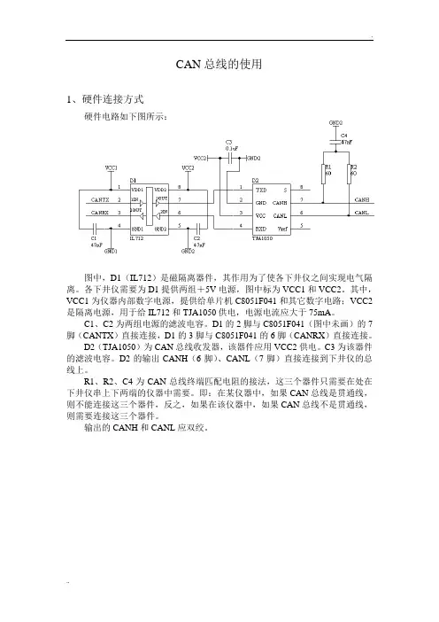
CAN总线的使用1、硬件连接方式硬件电路如下图所示:图中,D1(IL712)是磁隔离器件,其作用为了使各下井仪之间实现电气隔离。
各下井仪需要为D1提供两组+5V电源,图中标为VCC1和VCC2。
其中,VCC1为仪器内部数字电源,提供给单片机C8051F041和其它数字电路;VCC2是隔离电源,用于给IL712和TJA1050供电,电源电流应大于75mA。
C1、C2为两组电源的滤波电容。
D1的2脚与C8051F041(图中未画)的7脚(CANTX)直接连接,D1的3脚与C8051F041的6脚(CANRX)直接连接。
D2(TJA1050)为CAN总线收发器,该器件应用VCC2供电。
C3为该器件的滤波电容。
D2的输出CANH(6脚)、CANL(7脚)直接连接到下井仪的总线上。
R1、R2、C4为CAN总线终端匹配电阻的接法,这三个器件只需要在处在下井仪串上下两端的仪器中需要。
即:在某仪器中,如果CAN总线是贯通线,则不能连接这三个器件,反之,如果在该仪器中,如果CAN总线不是贯通线,则需要连接这三个器件。
输出的CANH和CANL应双绞。
2、软件使用方法编程者应该熟悉以下两本资料:《C8051F040/1/2/3/4/5/6/7混合信号ISP FLASH微控制器数据手册》《Bosch’s C_CAN User’s Manual》在下井仪中建议采用C8051F041或C8051F040单片机,该单片机内部集成了Bosch CAN控制器。
以下简要介绍C8051F04x单片机和Bosch CAN控制器及其软件编程方法。
2.1 C8041F04x单片机SFR的分页机制C8051F04x系列MCU对CIP-51内核和外设有几项关键性的改进,提高了整体性能。
其中与编程密切相关的一点是使用了SFR(特殊功能寄存器)分页机制,允许器件将很多SFR映射到0X80~0XFF这个存储器空间。
C8051F04x器件使用了5个SFR页:0、1、2、3和F。
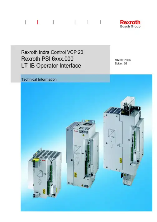
Rexroth Indra Control VCP 20Rexroth PSI 6xxx.000LT-IB Operator Interface Technical Information 1070087066 Edition 02II Bosch Rexroth AG Electric Drives PSI 6xxx.000 1070087066 / 02and ControlsTitle Rexroth PSI 6xxx.000LT-IB operator interfaceType of Documentation Technical InformationDocument Typecode DOK-PS6000-LT-IB*****-FK02-EN-PPurpose of Documentation The present manual provides information on●Installation and●functionalityof the “LT-IB” operator interface/parameterization software.Record of Revisions Description ReleaseNotesDate−−−−DOK-PS6000-LT-IB*****-FK02-EN-P 03.2005Copyright © Bosch Rexroth AG, 2003−2005Copying this document , giving it to others and the use orcommunication of the contents thereof without expressauthority, are forbidden. Offenders are liable for the paymentof damages. All rights are reserved in the event of the grantof a patent or the registration of a utility model or design (DIN34-1).Validity The data specified above only serve to describe theproduct. No statements concerning a certain condition orsuitability for a certain application can be derived from ourinformation. The given information does not release theuser from the obligation of own judgement and verification. Itmust be remembered that our products are subject to anatural process of wear and aging.Published by Bosch Rexroth AGPostfach 11 62D-64701 ErbachBerliner Strafle 25D-64711 ErbachTel.: +49 (0) 60 62/78-0Fax: +49 (0) 60 62/78-4 28Abt.: BRC − WS/VTRContentsContentsPage3 Operation 3−13.1 Starting / Exiting the software 3−13.2 Setting the basic parameters 3−23.3 Parameterizing the setpoint input 3−93.4 Setting the date/time 3−11 3.5 Displaying the device type and the firmware version 3−113.6 Displaying the error log 3−113.7 Fault reset 3−123.8 Backing-up data 3−123.9 Restoring data backups 3−133.10 Triggering device Reset 3−13 3.11 Loading factory setting of the device 3−14Operation3 Operation3.1 Starting / Exiting the software★Before starting the LT-IB software, you should make sure that the 24 V supply voltage for the digital welding current source has been switchedon.This is indicated by the “LOGIC” LED on the front panel of the interfacemodule:LOGIC LED, green. Is on if 24 V DC (logicsupply voltage) is available.●Start the LT-IB software by double-clicking on the link symbol createdin the course of installation.☞If the program window remains empty after the start, or if it closesagain automatically, the software is not able to detect a digital weldingcurrent source at either of the serial interfaces of the PC. In this case, you should check whether●the connecting cable has been properly wired and plugged in.●the 24 V supply to the digital welding current source has beenswitched on.If a digital welding current source is connected and has beendetected, the main menu of the software will appear as follows:Device type andfirmware version ofthe digital weldingcurrent sourceconnectedMain menuInput prompt3−2 Bosch Rexroth AG Electric Drives PSI 6xxx.000 1070087066 / 02 and ControlsOperationThe cursor is flashing at the input prompt. In this condition, you can activate the functions displayed simply by pressing the corresponding key.For a description of the individual functions ofkey “P”: refer to Sect. 3.2 page 3−2.key “F”: refer to Sect. 3.6 page 3−11.key “K”: refer to Sect. 3.3 page 3−9.key “B”: refer to Sect. 3.8 page 3−12.key “R”: refer to Sect. 3.9 page 3−13.key “Z”: refer to Sect. 3.7 page 3−12.key “D”: refer to Sect. 3.4 page 3−11.key “N”: refer to Sect. 3.5 page 3−11.Keys “E” or “Esc”: exit the software.3.2 Setting the basic parameters------------------------------------------------------------------------------------------------------------------------------------ CAUTIONIncorrect parameter settings may damage the transformers, thewelding system, or produce incorrect welds. Therefore, you should notchange any parameters unless you are totally sure about theconsequences of such a change.In cases of doubt, please ask your supervisor!------------------------------------------------------------------------------------------------------------------------------------ Here, you can set the basic parameters of the digital welding currentsource. The display/query of some parameters depends on thecurrent firmware version and the parameter settings made for the unit:●Configuration (only if master/slave operationis supported by the inverter)●Regulation mode●Current measurement●Toroid sensitivity● Measuring range (with secondary currentmeasurement only)●Transformer type●Number of transformers●Type of transformer connection●Transformer ratio (for third-party transformers only)●Transformer secondary current (for third-party transformers only)● Diode type (for third-party transformers only)●Number of parallel diodes (for third-party transformers only)●Diode monitoring (on/off)1070087066 / 02 PSI 6xxx.000 Electric Drives Bosch Rexroth AG 3−3 and ControlsOperation★Press key “P” in the main menu while the cursor is at the input prompt.All necessary parameters are displayed one by one by the system,queried, a nd immediately transmitted to the unit after acknowledgment by the “Enter” or “Esc” key.☞If you do not want to change a parameter, press the “Enter” or “Esc” keywithout entering a value.When all parameters have been displayed/queried, the main menu is built up again.Example:Resulting query sequence with the following parameter input:●Configuration as master with 1 slave●KSR mode (current regulation)●Primary current measurement●Toroid sensitivity = 150●Connection of 1 x transformer PSG 3100.00●Diode monitoring is active●Normal controller dynamics3−4 Bosch Rexroth AG I Electric Drives PSI 6xxx.000 1070087066 / 02 and ControlsOperationRegulation modePossible settings:●0 : Pulse width mode (PHA mode)The welding heat within the welding circuit is influenced by changing thepulse width. The pulse width only depends on the command value present in this case.● 2 : Current regulation (KSR mode)The programmed current (in kA) is determined by the command value signal supplied (0 to 10 V DC). There is closed-loop control of the actual current in the secondary circuit. The welding heat within the welding circuit is influenced by the controller which changes the pulse width as needed.★Make sure that the setting matches the type of command value input by the external weld timer!☞For more information on the regulation modes, refer to the manual “Controland I/O level, Technical Information (1070 087 065)”, keyword “Regulationmodes”.Current measurementPossible settings:●0 : Primary current measurementAn sensor integrated in the primary circuit inside the device is used as current sensor. The device converts the measured value into the correspondingsecondary current based on the transformer parameter settings.● 1 : Secondary current measurementAn external current sensor linked to X3 is used in the secondary circuit.☞The following applies for secondary current measurement: max. weld time< 1s!1070087066 / 02 PSI 6xxx.000 Electric Drives Bosch Rexroth AG 3−5and ControlsOperationToroid sensitivityInternal evaluation factor for the measured current.This function may be used to adjust the device to an external currentmeasuring unit (reference ammeter) (calibration).Measuring range☞ The parameter is only offered if secondary current measurement is active.Possible settings:●11 : 0.5 to 5 kA●12 : 1 to 10 kA●13 : 2 to 20 kA●14 : 4 to 40 kA●15 : 8 to 80 kA●16 : 16 to 160 kADefines the current range covered by the currents to be measured.★Please make sure that the measuring range set for the currents to bemeasured is not too small. The measured currents should be in the upperthird of a measuring range.Transformer typePossible settings:●0 : PSG 3050.00● 1 : PSG 3050.10● 2 : PSG 3075.10● 3 : PSG 3100.00● 4 : PSG 3200.00● 5 : no PSG transformer (third-party transformer)From this setting, the unit derives certain PSG transformer parameters fordiode monitoring and conversion from primary into secondary current values.★After having changed this parameter, you should perform a device reset(refer to Sect. 3.10 page 3−13) as soon as the main menu was built up again!3−6 Bosch Rexroth AG Electric Drives PSI 6xxx.000 1070087066 / 02 and ControlsOperationNumber of transformersPossible settings:● 1 to 8Number of welding transformers connected to the unit.★After having changed this parameter, you should perform a device reset(refer to Sect. 3.10 page 3−13) as soon as the main menu was built up again!Type of transformer connectionPossible settings:●0 : serial● 1 : parallelYou specify whether the welding transformers on the secondary side areconnected in parallel or in series.★After having changed this parameter, you should perform a device reset(refer to Sect. 3.10 page 3−13) as soon as the main menu was built up again! Transformation ratio☞The parameter is only offered for third-party transformers(trans former type = 5).It specifies the transformation ratio (primary/secondary side) of the welding transformers used.Maximum transformer secondary current☞The parameter is only offered for third-party transformers(trans former type = 5).Specifies the maximum permitted secondary current of the transformer(in kA).1070087066 / 02 PSI 6xxx.000 Electric Drives Bosch Rexroth AG 3−7and ControlsOperationType of diode☞ The parameter is only offered for third-party transformers(trans former type = 5).Possible settings:●0 : SKN 4000● 1 : SKN 6000● 2 : SDD71B0200● 3 : D 4457 NSpecifies the diode types the transformers in use are equipped with.★After having changed this parameter, you should perform a device reset(refer to Sect. 3.10 page 3−13) as soon as the main menu was built up again! Number of parallel diodes☞ The parameter is only offered for third-party transformers(transformer type = 5).Possible settings:● 1 to 4Specifies the number of diodes connected in parallel in the transformer per branch.Diode monitoring active------------------------------------------------------------------------------------------------------------------------------------ CAUTIONPossibility of destroying the power unit or the welding transformer!If diode monitoring is not active, the diodes of the welding transformer are no longer monitored by the PSI. In the event of excessive load, this may result in considerable damage to the welding equipment.Therefore, diode monitoring should always be switched on.------------------------------------------------------------------------------------------------------------------------------------ Possible settings:●0 : Monitoring deactivated● 1 : Monitoring activated★After having changed this parameter, you should perform a device reset(refer to Sect. 3.10 page 3−13) as soon as the main menu was built up3−8 Bosch Rexroth AG Electric Drives PSI 6xxx.000 1070087066 / 02 and ControlsOperationController adjustmentPossible settings:●−10 to 10, step size 1. Default setting: 0.Influences the dynamics of the constant-current regulator.Negative values mean a potentially slower current rise, positive values afaster current rise.------------------------------------------------------------------------------------------------------------------------------------ CAUTIONOscillation of current control is possible!Changing this parameter to inappropriate values may cause the control tooscillate and lead to improper welds!After having changed this parameter, please check whether the resultingcurrent characteristic during the weld is correct.------------------------------------------------------------------------------------------------------------------------------------1070087066 / 02 PSI 6xxx.000 Electric Drives Bosch Rexroth AG 3−9 and ControlsOperation3.3 Parameterizing the setpoint input☞The parameter settings for the command value input are not active unless KSR regulation mode has been selected.In order to optimally adjust the setpoint signal input of the digital weldingcurrent source (at X2, input voltage range: 0 to 10 V DC) to the setpoint signal of an external controller, two pairs of values can be parameterized (voltage inmV, resulting welding current in kA) to specify a linear characteristic.The digital welding current source will then use this characteristic to convert any active voltage to the corresponding command current.★Proceed as follows to set the parameters for these two pairs of values:1. Press key “K” in the main menu while the cursor is at the input prompt.The system then waits for input of the first voltage value.☞If you do not want to change the currently active characteristic, press the“Enter” or “Esc” key without entering a value in subsequent steps 2, 3, 4 or 5.After having queried all values, the system will report “Function aborted –please repeat” in this case without changing the existing characteristic.2. Enter the first voltage value in mV.The lower one of the two voltages must be input at this point. In theexample below, this would be 2000.Acknowledge the value input with the “Enter” key.The system then waits for input of the first current value.3. Enter the first current value in kA.The lower one of the two current values must be input at this point. In theexample below, this would be 60.Acknowledge the value input with the “Enter” key.The system then waits for input of the second voltage value.4. Enter the second voltage value in mV.The higher one of the two voltages must be input at this point. In theexample below, this would be 10000.Acknowledge the value input with the “Enter” key.The system then waits for input of the second current value.5. Enter the second current value in kA.The higher one of the two current values must be input at this point. In the example below, this would be 120.Acknowledge the value input with the “Enter” key.The system calculates the characteristics from the data input and showsthe resulting currents for the input voltages of 0 V and 5 V as controloutput.The main menu is built up again afterwards.3−10 Bosch Rexroth AG Electric Drives PSI 6xxx.000 1070087066 / 02 and ControlsOperationExample for Type PSI 6500.000:Desired adjustment toexternal controller:Parameter input procesdurecorresponding to step 2. to 5.(see above):1st pair of values2nd pair of valuesControl displayParameter input for the setpoint signal input☞ Please note that voltage values below 1 V are basically interpreted as 0 V, therefore, no activity is initiated.1070087066 / 02 PSI 6xxx.000 Electric Drives Bosch Rexroth AG 3−11 and ControlsOperation3.4 Setting the date/timeThis function will copy the current date and the current time of the PC to the digital welding current source.☞ Errors cannot be logged properly unless these values have been setcorrectly!★Proceed as follows:1. Check whether the date and time settings of the PC are correct.Otherwise, set the proper date and time at the PC.2. Press key “D” in the main menu while the cursor is at the input prompt.The time settings of the PC and the digital welding current source havebeen synchronized.The main menu is built up again.3.5 Displaying the device type and the firmware versionDisplays the device type and the firmware version.★Press key “N” in the main menu while the cursor is at the input prompt.The information is displayed, and the main menu is built up again afterwards.3.6 Displaying the error logDisplays the internal error log − starting with the error that occurredlast − page by page on the screen.★Press key “F” in the main menu while the cursor is at the input prompt.●Enter key:scrolling by pages through the error log●“Esc” key:cancels the error log display.When the last page of the error log has been displayed or if the display has been canceled, the main menu is built up again.3−12 Bosch Rexroth AG Electric Drives PSI 6xxx.000 1070087066 / 02 and ControlsOperation3.7 Fault resetWhile the digital welding current source automatically resets“selfacknowledging errors” as soon as the corresponding error condition no longer exists, “non-self-acknowledging errors “ must be reset manually using “Fault reset”.Whether or not an error is currently pending is indicated on the front panel of the interface module.☞For more details concerning possible errors, please refer to the“Display error log” function (refer to Sect. 3.6).★First, the cause of the error should be corrected.★Press key “Z” in the main menu while the cursor is at the input prompt.The main menu is built up again.If the error condition is no longer present, the “READY” LED on the frontpanel of the interface module will be lit again.3.8 Backing-up dataFor backup purposes or for series commissioning of a plant, the currentparameter settings of the digital welding current source can be saved on the PC:“Data backup” can be performed at any time, even during a weldingschedule.★Press key “B” in the main menu while the cursor is at the input prompt.The complete parameter settings are saved to the “BACKUP.SST” file in thecurrent working directory.When the process is finished, main menu is built up again.☞ To restore the data: refer to section 3.9.1070087066 / 02 PSI 6xxx.000 Electric Drives Bosch Rexroth AG 3−13 and ControlsOperation3.9 Restoring data backupsWhen the parameters of the digital welding current source have alreadybeen backed up (refer to “Backing-up data”, Section 3.8), the backup datacan be restored when necessary.☞ Backup data can be restored to a device of the same type only!------------------------------------------------------------------------------------------------------------------------------------ CAUTION“Restore” will interrupt the currently active welding process!This will result in an incorrect weld. Therefore, you should only use thisfunction if●the unit is not involved in a production process.------------------------------------------------------------------------------------------------------------------------------------ ★Proceed as follows:1. Make sure that the “BACKUP.SST” file containing the appropriateparameters exists in the current working directory.2. Press key “R” in the main menu while the cursor is at the input prompt.3. Then confirm the query “Are you sure” by hitting “Y”.Any other key will abort the function.The Ready status of the unit is deactivated while data is being restored.During this time span, welding is not possible.If there is no error, the unit will automatically restore the Ready condition when the data restoring process has been completed.The main menu is built up again.3.10 Triggering device ResetUse this function to reboot the digital welding current source.This process is equivalent to reinitialization of the device and may benecessary after certain parameter changes (e.g. in the area of diodemonitoring) in order to ensure proper functioning.Where this is the case, you will be informed accordingly.------------------------------------------------------------------------------------------------------------------------------------ CAUTIONDevice Reset will interrupt the currently active welding process! This willresult in an incorrect weld. Therefore, you should only use this function if●the unit is not involved in a production process.------------------------------------------------------------------------------------------------------------------------------------------------3−14 Bosch Rexroth AG Electric Drives PSI 6xxx.000 1070087066 / 02 and ControlsOperation★Press key “*” in the main menu while the cursor is at the input prompt.The device is rebooted without any further safety query.The main menu is built up again.3.11 Loading factory setting of the deviceThis option should be used in order to●reset all parameters of the digital welding current source to their defaultvalues, and●delete the contents of all process log memories.------------------------------------------------------------------------------------------------------------------------------------ CAUTIONLoading the factory settings of the device will delete the current parameter settings!The default value settings (e.g. transformer values, characteristic forconverting the setpoint signal into a current setpoint) may not be suitable for your specific application. Therefore, you should only use this function if●you are fully aware of its consequences●the unit is not involved in a production process.------------------------------------------------------------------------------------------------------------------------------------ ☞Deleting the process log memory contents of units that are involved in theproduction process is not permitted by quality assur a nce in many cases.If you are not sure whether or not the process log memory contents of thedevice may be deleted, please contact your supervisor.★Proceed as follows:1. Press key “L” in the main menu while the cursor is at the input prompt.2. Then confirm the query “Are you sure” by hitting “Y”.Any other key will abort the function.The main menu is built up again.BOSCH psi6500.000現有參數設定值:Regulation mode :( 0: Pulse width mode (PHA mode), 2: Current regulation (KSR mode)) Possible settings: 2Current measurement (0:Primary 1: Secondary)Possible settings: 1Sensor responsiveness :Possible settings: 150Measuring range : ( 11:5kA ;12:10kA;13:20kA; 14:40kA; 15:80kA; 16:160kA)Possible settings: 15Transformer type: (0: PSG 3050.00, 1: PSG 3050.10. 2: PSG 3075.10, 3: PSG 3100.00, 4: PSG 3200.00, 5:OEM)Possible settings: 5Number of transformers :Possible settings: 4Type of transformer connection :( 0: serial, 1: parallel)Possible settings: 1Transformation ratioPossible settings: 55Maximum transformer secondary currentPossible settings: 0Type of diode:( 0: SKN 4000, 1: SKN 6000, 2: SDD71B0200, 3: D 4457 N)Possible settings: 0Number of parallel diodes : (1-4)Possible settings: 2Diode monitoring active : ( 0:off, 1: on)Possible settings: 1BOSCH psi6500.000 KSR現有設定值3.3 Parameterizing the setpoint inputThe parameter settings for the command value input are not active unless KSR regulation mode has been selected.aborted −please repeat. in this case without changing the existing characteristic.2. Enter the first voltage value in mV. 10003. Enter the first current value in kA. 104. Enter the second voltage value in mV.100005. Enter the second current value in kA. 483-2 Bosch Rexroth AG | Electric Drives PSG 6xxx. | 1070087063 / 03 andControlsTransformer selection3.2 Technical dataNameTypes PSG ...3075.10 xx 6130.00 xxNominal power SN 80 kVA (at 20% duty cycle) 130 kVA (at 20% duty cycle) maximum primary continuous current I1P76 A 118 APrimary voltage U1N 500 Vmaximum DC current Idmax refer to load diagrams in the sections that deal with thetransformersContinuous DC current Id (100% duty cycle) 4.2 kA 6.5 kA No-load DC voltage UdiO 8.4 V 9 V Frequency f (primary circuit) 1000 HzSensitivity Ratio 55 : 1min. conductor area (primary circuit) 16 mm2 35 mm2 min. cooling water quantity 6 l/min 8 l/min max. cooling water temperature 30° Cmax. cooling water pressure drop refer to differential pressure diagrams in the sections that dealwith the transformersmax. operating temp. (primary winding) 150° Cmax. operating temperature (diodes) 80° CDegree of protection of transformer block IP65Degree of protection(connection zone on primary side)1)Degree of protection(connection zone on secondary side)IP00Insulation class of welding transformers FWeight 14.5 kg 16 kg Dimensions and locations of connections refer to dimensioned drawingsColor RAL 7005; grey RAL 1004; yellow 1) With terminal box: IP55; without terminal box: IP009-40 Bosch Rexroth AG | Electric Drives PSI 6xxx. | 1070080059 / 02 andControlsPSI 6500.xxx W19.6.2 Technical dataType 3-phase rack-mounted mid-frequency converterWeld timer integratedI/O interface Slot for parallel, serial or fieldbus interfaceQuality module Slot provided for later additionDegree of protection IP 20; designed for installation in housing or switch cabinet with IP 54 Storage temperature range −25° C to +70° COperating temperature range (in installation space) +10° C to +45° C; in the case of a thermal capacity that is greater than half of the nominal capcity, a cabinet cooler that regulates the cabinet temperature to 35 degrees Celsius is used.Cooling using water; 10 l/min; supply flow max. 30° C Temperature monitoring integratedCorrosion The ambient air must be free of high concentrations of acids, brines, corrosives, salt and metallic vapors.Humidity 3K3 according to EN 60721−3−3 Condensation on the mid-frequency converter is not permitted.Air pressure 0 to 2000 m above sea level.Main supply voltage connection to grounded TN or TT network. 400 V −20% to 480 V +10%; 50/60 Hz Nominal main supply voltage(maximum thermal continuouscurrent)660 A (with cabinet cooler) 330 A (without cabinet cooler)Max. output current(primary current)2400 AMax. secondary current(transformer−dependent)120 kA (with PSG 3100)Logic main supply(e.g. for weld timer CPU, I/O interfaces, etc.) 24 V=, min: 19 V=; max: 30 V=, acc. to EN 61131-2. Supply possibilities: using external power pack; using separate supply with the integrated power pack (from the welding main supply).1070080059 / 02 | PSI 6xxx Electric Drives | Bosch Rexroth GmbH 9-41and ControlsPSI 6500.xxx W1Over voltage protection MOV (metal oxide varistor)Electrical connection main supply andusing terminal ends; M10 screws per connectiontransformerWire range 2−4 cables per 120 mm2Basic switchgear cabinet losses 100 Wmax. cooling losses 4400 WSwitchgear cabinet losses at max. power 850 WWeight approx. 70 kg; mechanically divisibleMounting position vertical or lying on rearProduct informationPerformance chartSecondary current ranges of PSI 6xxxs from thermal current up to peak current with 9VTransformers3* PSI 6500 2* PSI 6500PSI 6500PSI 6400PSI 6200PSI 6300PSI 6100PSI 60256V transformerThe master/slave conceptThe PSI 6500 inverter can be operated in a master/slave configuration to increase its power. In this mode, up to 3 units can be connected in parallel. Each inverter is connected to one or several identical transformers in this case.The transformers can then be connected in parallel on the secondary side in a simple symmetrical configuration in order to achieve three times the power of one individual unit. The hardware of the units is identical. The slave or master function is selected by suitable parameter settings.Technical dataBosch Rexroth AG“The Drive & Control Company”Vertriebskoordination WiderstandsschweißenPostfach 1162D-64701 Erbach/OdenwaldTel: +49 (0)60 62-78-231Fax: +49 (0)60 62-78-728。

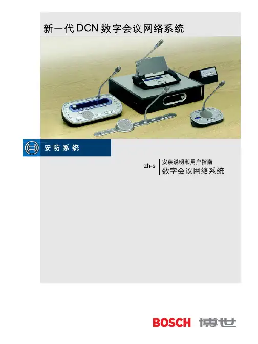
BOSCH 同声传译系统说明中央控制器通过内置的D/A转换器,将会议系统的音频信号输入到混音功放进行扩声,并可将外部的声源信号通过中央控制器接入DCN系统,代表可在面板扬声器和耳机中直接收听。
BOSCH(原PHILIPS)数字会议网络系统(DCN)首开在研讨、代表、大型国际会议中应用数字技术的先河,它的信号传输和处理均采用了数字音频技术,具有多功能、高音质、数据传输保密可靠等特点,可对会议过程实行全面的控制,对各类型的会议都能提供灵活的管理,不论是非正式的小型会议,还是上千人的国际大型会议。
DCN是同类设备中率先采用全数字技术的系统。
具有多功能、高音质、数据传送保密可靠等特点,可以满足现代会议的一切管理需求,包括:基本的话筒管理,代表认证和登记,电子表决,资料分配和显示以及多语种的同声传译。
系统的信号和处理采用了久经考验的飞利浦数字音频技术。
比如在会议代表用的话筒中采用了高性能的“Bitstream”系统进行模-数转换。
由于采用了先进的数字技术,在传输过程中信号的质量和幅度都不会衰减,因此音频的技术性能达到了空前的水平。
使得每一个与会者都可以听到稳定、纯正的声音。
这一点对提高发言的清晰度无疑有重要的贡献。
DCN从根本上消除了一般会议系统的缺陷,如背景噪音、干扰、失真和串音等。
DCN数字技术的另一个重要优点是安装速度快,节约经费。
用一根细而软的双同轴电缆可以传送系统的全部数字信号,并且可以在任意点上“搭接”补充发言机或其他DCN设备。
因此在以后需要将系统的容量进一步扩大时,不必改动系统原来的接线即可进行扩容。
各设备的电源也是同一根电缆上的两根线提供的。
DCN的控制系统有两种选择:一种是以先进的、操作方便的软件设施调整与控制。
另一种是无机务人员的自动控制。
系统的应用软件能把会议的准备、管理、控制置于计算机环境中,微软视窗允许同时运行多个软件,并可在各应用软件之间进行信息传递。
视窗的图形用户界面具有非常的直观性。
bus规范V2.0版本引言随着串行通讯进入更多应用领域在一些应用里原先的地址范围由11个识别位定义则这些应用就可以更好地由CAN来实现由29位定义有的用户不需要由扩展格式提供的识别符范围可以采用市场上可用的CAN仪器为了区别标准格式和扩展格式使用了CAN报文格式的第一个保留位因此仍然是有效的由于扩展格式已经定义这本CAN规范技术规范由两部分组成CAN的报文格式说明标准格式和扩展格式的说明要求CAN的仪器应兼容A部分或B部分只要没有用到扩展格式根据A部分或CAN旧版本设计的仪器可以和根据B部分设计的仪器相互间进行通讯介绍 (3)2报文传输 (6)3.1 帧类型 (6)3.1.1 数据帧 (6)3.1.2 远程帧 (9)3.1.3 错误帧 (10)3.1.4 过载帧 (11)3.1.5 帧间空间 (11)3.2 发送器/接收器的定义 (12)4编码 (13)6故障界定 (13)8介绍控制器局域网为串行通讯协议CAN的应用范围很广在汽车电子行业里传感器等等同时诸如车灯组用以代替接线配线装置可是比如电气特性和数据转换的解释CAN被细分为以下不同的层次the object layerthe transfer layerthe phyical layer¶ÔÏó²ãµÄ×÷Ó÷¶Î§°üÀ¨l 确定由实际要使用的传输层接收哪一个报文在这里传输层的作用主要是传送规则执行仲裁出错标定总线上什么时候开始发送新报文及什么时候开始接收报文位定时的一些普通功能也可以看作是传输层的一部分传输层的修改是受到限制的当然物理层对于所有的节点必须是相同的在选择物理层方面还是很自由的并定义CAN协议于周围各层当中所发挥的作用基本概念CAN具有以下的属性就自动将破坏的报文重新传输• 将节点的暂时性错误和永久性错误区分开来Layered Structure od a CAN node±¾¼¼Êõ¹æ·¶Ã»Óж¨ÒåÎïÀí²ã¶Ô·¢ËÍýÌåºÍÐźŵçƽ½øÐÐÓÅ»¯Ëü°Ñ½ÓÊÕµ½µÄ±¨ÎÄÌṩ¸ø¶ÔÏó²ã´«Êä²ã¸ºÔðλ¶¨Ê±¼°Í¬²½ÖٲôíÎó¼ì²âºÍ±ê¶¨l 对象层的功能是报文滤波以及状态和报文的处理所具有的意义Messagesµ«³¤¶ÈÊÜÏÞ信息路由 在CAN系统里比如l 系统灵活性就可以在CAN网络中直接添加节点报文的内容由识别符命名但解释数据的含义网络上所有的节点可以通过报文滤波确定是否应对该数据做出反应由于引入了报文滤波的概念并同时对此报文做出反应在CAN网络内或同时不被接收系统的数据连贯性是通过多播和错误处理的原理实现的Bit rateCAN的速度不同在一给定的系统里并且是固定的Prioritiesʶ±ð·û¶¨ÒåÒ»¾²Ì¬µÄ±¨ÎÄÓÅÏÈȨRemote Data RequestÐèÒªÊý¾ÝµÄ½Úµã¿ÉÒÔÇëÇóÁíÒ»½Úµã·¢ËÍÏàÓ¦µÄÊý¾ÝÖ¡IDENTIFIERMultimasterÈκε¥Ôª¶¼¿ÉÒÔ¿ªÊ¼´«Ëͱ¨ÎÄ仲裁任何单元都可以开始发送报文那么就会有总线访问冲突仲裁的机制确保信息和时间均不会损失数据帧优先于远程帧每一个发送器都对发送位的电平与被监控的总线电平进行比较则这个单元可以继续发送隐性显性见总线值必须退出发送状态SafetyCAN的每一个节点均采取了强有力的措施以进行错误检测错误检测必须采取以下措施发送器对发送位的电平与被监控的总线电平进行比较Performance of Error Detection- 检测到所有的全局错误- 检测到发送器所有的局部错误- 可以检测到一报文里多达5个任意分布的错误- 检测到一报文里长度低于15µÄÍ»·¢ÐÔ´íÎó- 检测到一报文里任一奇数个的错误对于没有被检测到的错误报文报文错误率* 4.7 * 10 –11Error Sinalling and Recovery Time´Ë±¨ÎÄ»áʧЧ²¢½«×Ô¶¯µØ¿ªÊ¼ÖØд«ËÍ´Ó¼ì²âµ½´íÎóµ½ÏÂÒ»±¨ÎĵĴ«ËÍ¿ªÊ¼ÎªÖ¹故障界定永久故障的节点会被关闭ConnectionsÀíÂÛÉϵ«ÓÉÓÚʵ¼ÊÉÏÊÜÑÓ³Ùʱ¼äÒÔ¼°/或者总线线路上电气负载的影响Single Channelͨ¹ý´ËͨµÀ¿ÉÒÔ»ñµÃÊý¾ÝµÄÔÙͬ²½ÐÅÏ¢ÓÐÐí¶àµÄ·½·¨¿ÉÒÔ²ÉÓüÓÉϽӵعâÀµȵȼ´Î´¶¨ÒåÎïÀí²ãBus value»ò显性隐性总线的结果值为在执行总线的时显性逻辑1代表等级比如光Acknowledgment¶ÔÓÚÁ¬¹áµÄ±¨ÎĶÔÓÚ²»Á¬¹áµÄ±¨ÎÄ睡眠模式可以将CAN器件设为睡眠模式以便停止内部活动及断开与总线驱动器的连接或系统内部状态而被唤醒虽然传输层要等待一段时间使系统振荡器稳定通过检查11个连续的的位总线在线内部运行已重新开始可以使用一特殊的唤醒报文最低等级的识别符rrr rrrd rrrr; r = d=- 数据帧- 远程帧请求发送具有同一识别符的数据帧任何单元检测到一总线错误就发出错误帧过载帧用以在先行的和后续的数据帧之间提供一附加的延时或远程帧帧起始控制场CRC场帧结尾 帧起始它标志数据帧和远程帧的起始显性只在总线空闲信号参见Interframe Spac eInterfram eSpac eRTRʶ±ð·ûµÄ³¤¶ÈΪ11位最低位是ID-0ID-10到ID-4¸ÃλÔÚÊý¾ÝÖ¡Àï±ØÐëΪÒþÐÔ控制场控制场由6个位组成所发送的保留位必须为显性隐性数据长度代码数据长度代码为4个位DATA LENGTH CODEd显性012345678d d d d d d d d rd d d d r r r r dd d r r d d r r dd r d r d r d r d其他的数值不允许使用它可以为0ÿ×Ö½Ú°üº¬ÁË8个位 CRC 场CRC 场包括CRC序列CRC DELIMITERÓÉÑ-»·ÈßÓàÂëÇóµÃµÄÖ¡¼ì²éÐòÁÐ×îÊÊÓÃÓÚλÊýµÍÓÚ127位的帧被除的多项式系数由无填充位流给定帧起始控制场假如有将此多项式被下面的多项式发生器除CRC SEQUENCE¿ÉÒÔʹÓÃ15位的位移寄存器CRC_RG ËüÓÉ´ÓÖ¡µÄÆðʼµ½Êý¾Ý³¡Ä©Î²¶¼ÓÉÎÞÌî³äµÄλÐòÁиø¶¨CRC SEQUENCE1414:113:0014:014:04599hexCRC序列开始或存在一个错误条件CRC_RG 包含有CRC 序列它包含一个单独的位°üº¬Ó¦´ð¼ä϶和应答界定符发送站发送两个位接收器就会在应答间隙期间向发送器发送一的位以示应答CRC Fi eldACK Sl o tACK D elimiterEnd of Fr ameACK F IELDËùÓнÓÊÕµ½Æ¥ÅäCRC 序列的站会在应答间隙期间用一的位写入发送器的位来作出回答ACK 界定符是ACK 场的第二个位隐性因此ACK SLOTµÄλËù°üΧCRC DELIMITERACKDELIMITERÕâ¸ö±êÖ¾ÐòÁÐÓÉ7个位组成作为某数据接收器的站通过其资源节点对不同的数据传送进行初始化设置帧起始控制场应答场与数据帧相反隐性它没有数据场可以标注为容许范围里0...8的任何数值Int erSp ac eRTR位RTRµÚÒ»¸ö³¡ÓÃ×÷Ϊ²»Í¬Õ¾ÌṩµÄ´íÎó±êÖ¾的叠加为了能正确地终止错误帧错误被动如果的接收器有本地错误的话总线的载荷不应为100%Ö÷¶¯´íÎó±êÖ¾和被动错误标志显性被动错误标志由6个连续的的位组成显性检测到错误条件的的站通过发送主动错误标志错误标志的形式破坏了从帧起始到CRC界定符的位填充规则所有其他的站由此检测到错误条件并与此同时开始发送错误标志位位可以在总线上监视这个顺序的总长度最小为6个位检测到错误条件的的站试图通过发送被动错误标志的站等待6个相同极性的连续位被动错误标志的发送就完成了ÒþÐÔ错误标志传送了以后隐性隐性然后就开始发送7位以上的位过载标志和过载界定符1. 接收器的内部条件显性由过载条件1而引发的过载帧只允许起始于所期望的间歇场的第一个位时间开始显性Á½¸ö¹ýÔØÖ¡¶¼»á²úÉúÏÔÐÔ¹ýÔرêÖ¾µÄËùÓÐÐÎʽºÍÖ÷¶¯´íÎó±êÖ¾µÄÒ»ÑùÒò´ËÏÔÐÔÔòÆäËûµÄ½Úµã½«²»ÄÜÕýÈ·µØ½âÊ͹ýÔرêÖ¾ÏÔÐÔÕâµÚ6个的位破坏了产生错误条件的位填充的规则过载界定符过载界定符包括8个的位过载标志被传送后显性隐性过渡形式总线上的每一个站完成了过载标志的发送隐性3.1.5 帧间空间 数据帧与其前面帧的隔离是通过帧间空间实现的数据帧错误帧过载帧与错误帧之前没有帧间空间帧间空间帧间空间包括间歇场如果的站已作为前一报文的发送器时总线空闲外SUSPEND TRANSMISSION´íÎ󱻶¯»òÕß´ËÕ¾ÒÑ×÷Ϊǰһ±¨ÎĵĽÓÊÕÆ÷´íÎ󱻶¯ÆäÖ¡¼ä¿Õ¼äÈçÏÂͼËùʾÒþÐÔ间歇期间唯一要做的是标示一个过载条件时间任何等待发送信息的站就会访问总线有报文被挂起其传送起始于间歇之后的第一个位显性挂起传送µÄÕ¾·¢Ëͱ¨ÎĺóÒþÐÔÈç¹ûÓë´ËͬʱÁíÒ»Õ¾¿ªÊ¼·¢Ëͱ¨ÎÄ3.2 发送器/接收器的定义发送器 产生报文的单元被称之为报文的ARBITRATIONRECEIVERÔòÕâÒ»µ¥Ôª¾Í±»³Æ֮Ϊ±¨ÎĵÄ报文校验校验报文是否有效的时间点发送器Ôò´Ë±¨ÎĶÔÓÚ·¢ËÍÆ÷ÓÐЧÔò±¨ÎÄ»á¸ù¾ÝÓÅÏÈȨ×Ô¶¯ÖØ·¢ÖØд«Êä±ØÐëÔÚ×ÜÏß¿ÕÏÐʱÆô¶¯如果直到一最后的位均没有错误5帧的部分仲裁场数据场以及CRC序列无论何时便自动在位流里插入一补码位CRC界定符的剩余位场形式相同错误帧和过载帧的形式也相同其报文里的位流根据之方法来编码在整个位时间里显性要么为错误处理6.1 错误检测有以下5种不同的错误类型• 位错误站单元在发送位的同时也对总线进行监视则在此位时间里检测到一个位错误ARBITRATION FIELDACK SLOTλµÄÇé¿öÊÇÀýÍâµÄ此时显性不会发出位错误显性也不视为位错误出现了第6个连续相同的位电平时• CRC错误CRC序列包括发送器的CRC计算结果如果计算结果与接收到CRC序列的结果不相符CRC ERRORÔò¼ì²âµ½Ò»¸öÐÎʽ´íÎóACK SLOTACKNOWLEDGMENT ERROR¶ÔÓڵĽڵãÖ÷¶¯´íÎó±êÖ¾¶ÔÓڵĽڵ㱻¶¯´íÎó±êÖ¾Õ¾¼ì²âµ½ÎÞÂÛÊÇλ´íÎóÐÎʽ´íÎóÕâ¸öÕ¾»áÔÚÏÂһλʱ·¢³ö´íÎó±êÖ¾ÐÅÏ¢´íÎó±êÖ¾µÄ·¢ËÍ¿ªÊ¼ÓÚACK½ç¶¨·ûÖ®ºóµÄλ故障界定至于故障界定•错误被动总线关闭错误主动µÄµ¥Ôª²»ÔÊÐí·¢ËÍÖ÷¶¯´íÎó±êÖ¾´íÎ󱻶¯¶øÇÒµ¥Ôª½«ÔÚÔ¤ÉèÏÂÒ»¸ö·¢ËÍ֮ǰ´¦Óڵȴý״̬¼ûµÄµ¥Ôª²»ÔÊÐíÔÚ×ÜÏßÉÏÓÐÈκεÄÓ°Ïì• 发送错误计数• 接收错误计数这些计数按以下规则改变可能要用到的规则不只一个接收错误计数就加1½ÓÊÕ´íÎó¼ÆÊýÆ÷Öµ²»¼Ó1ÏÔÐÔ½ÓÊÕ´íÎó¼ÆÊýÖµ¼Ó8·¢ËÍ´íÎó¼ÆÊýÆ÷Öµ¼Ó8发送器为注显性显性发送器因为填充错误而发送错误标志引起填充错误是由于填充位隐性但是却被监视为发送错误计数器值不改变如果发送器检测到位错误 5. 当发送主动错误标志或过载标志时位错误6. 在发送主动错误标志任何节点最多容许7个连续的λÿһ·¢ËÍÆ÷½«ËüÃǵķ¢ËÍ´íÎó¼ÆÊýÖµ¼Ó8当检测到第14个连续的位后显性在每一附加的8个连续位顺序之后得到应答及直到帧末尾结束没有错误除非已经是0Ôڳɹ¦µØ½ÓÊÕµ½±¨Îĺ󼰳ɹ¦µØ·¢ËÍÁËÓ¦´ðλ如果接收错误计数器值是0如果大于1279. 当发送错误计数器值等于或超过128时节点为错误被动10.当发送错误计数器值大于或等于256时总线关闭11. 当发送错误计数器值和接收错误计数器值都小于或等于127时错误被动错误主动12. 在总线监视到128次出现11个连续位之后总线关闭错误主动不再是 备注最好能够采取措施测试这个条件Æð¶¯/睡眠以及如果这个节点发送一些报文如此检测到错误并重复报文节点会变为总线关闭8标称位时间标称位时间 = 1 /标称位速率可以把标称位时间划分成了几个不重叠时间的片段同步段 传播时间段 相位缓冲段1相位缓冲段2位时间如下图所示SYN C_SEG PR OP_SEG PH ASE_SE G1PH AS E_SEG2SYNC SEGÕâÒ»¶ÎÄÚÒªÓÐÒ»¸öÌø±äÑØPROP SEG它是总线上输入比较器延时和输出驱动器延时总和的两倍相位缓冲段2ÕâÁ½¸ö¶Î¿ÉÒÔͨ¹ýÖØÐÂͬ²½¼Ó³¤»òËõ¶ÌSAMPLE POINT²É¼¯µãλÓÚÏàλ»º³å¶Î1之后INFORMATION PROCESS TIME²É¼¯µãÓÃÓÚ¼ÆËãºóÐøλµÄλµçƽTIME QUANTUM´æÔÚÓÐÒ»¸ö¿É±à³ÌµÄÔ¤±ÈÀýÒò×Ó32的整数时间份额的长度为TIME QUANTUM MINIMUM TIME QUANTUM m为预比例因子Length of Time SegmentsSYNC_SEG传播段的长度可设置为1…»º³å¶Î1 的长度可设置为1…Ïàλ»º³å¶Î2的长度为阶段缓冲段1和信息处理时间之间的最大值一个位时间总的的时间份额值可以设置在8同步 硬同步内部的位时间从同步段重新开始硬同步强迫由于硬同步引起的沿处于重新开始的位时间同步段之内RESYHCHRONIZATION JUMP WIDTHʹÏàλ»º³å¶Î1增长相位缓冲段加长或缩短的数量有一个上限重新同步跳转宽度应设置于1和最小值之间后续位有固定的最大数值这个属性提供了总线单元在帧期间重新和位流同步的可能性这里有一个属性只有后续位的一固定最大值才具有相同的数值可用于重新同步的两个过渡过程之间的最大长度为29个位时间一个沿的相位误差一个沿的相位误差由相关于同步段的沿的位置给出相位误差定义如下SYNC_SEGSAMPLE POINTSAMPLE POINTÖØÐÂͬ²½ºÍÓ²¼þͬ²½µÄ×÷ÓÃÏàͬ• 如果相位误差为正增长的范围为与重新同步跳转宽度相等的值则相位缓冲段2被缩短同步的原则硬同步和重新同步都是同步的两种形式1. 在一个位时间里只允许一个同步才把沿用作于同步有一转变到的沿硬同步都会被执行隐性显性则其他符合规则1和规则2的所有从转化为的沿可以用作为重新同步即隐性显性此沿具有正的相位误差9 增加CAN振荡器容差这章介绍CAN协议的向上兼容的修改有必要作以下修改以便向上兼容现有的CAN规范 如果CAN节点在间歇的第三位采集到一显性位2Ôò´Ëλ±»½âÊÍΪ֡µÄÆðʼλ¶ø²»ÊÇÊ×ÏÈ·¢ËÍÖ¡µÄÆðʼλ»ò³ÉΪһ½ÓÊÕÆ÷如果节点在错误界定符或过载界定符的第八个位采集到一显性位而不是错误帧4Ϊ·ûºÏÏÖÓеĹ淶56CAN才发送帧起始位 这个修改允许振荡器最大为1.58%的容差为了满足CAN协议的整个总线速度范围只要符合以下的要求8ËùÓеĿØÖÆÆ÷±ØÐëʹÓþ§Õñ具有最高振荡准确度要求的芯片只有在所有的节点使用增强型的CAN协议时才能使用陶瓷谐振器简介 (19)2 基本概念 (19)3报文滤波 (31)5 报文校验 (31)6错误处理 (31)7.1 错误检测 (31)7.2 错误标定 (32)8位定时要求 (33)简介控制器局域网CAN为串行通讯协议CAN的应用范围很广在汽车电子行业里传感器等等同时诸如车灯组用以代替接线配线装置可是比如电气特性和数据转换的解释根据ISO/OSI参考模型• 数据链路层- 逻辑链路控制子层(LLC)- 媒体访问控制子层 物理层注数据链路层的LLC子层和MAC子层的服务及功能分别被解释为和• 为远程数据请求以及数据传输提供服务• 为恢复管理和过载通知提供手段定义对象处理较为自由也就是控制帧结构错误检测故障界定均在MAC 子层里确定理所当然物理层的作用是在不同节点之间根据所有的电气属性进行位的实际传输尽管如此这本技术规范的目的是定义数据链路层中MAC子层和一小部分LLC子层所具有的意义• 报文的优先权• 保证延迟时间• 设置灵活• 时间同步的多点接收• 系统内数据的连贯性• 多主机• 错误检测和错误标定• 只要总线一处于空闲并且可以自动关闭由OSI参考模型分层CAN结构的错误的节点因此涉及到位时间同步的解释以便允许根据它们的应用• MAC子层是CAN协议的核心并接收来自LLC子层的报文仲裁错误检测和标定ÒÔ±ã°ÑÓÀ¾Ã¹ÊÕϺͶÌʱÈŶ¯Çø±ð¿ªÀ´¹ýÔØ֪ͨData LinkLay erPhys ica l Lay erLL CMA CAcceptan ce Fi ltering Over load N otification Recove ry Ma nagem entData E ncapsul ation /Decap sul ation Fr ame C oding(S tuffing, Des tuffing)Medium A ccess M anag emen t Error D etection E r ror Sig nalling Acknow ledgmentSe rializa tion / De se rializa tionBit E ncoding/Decoding Bit T iming Synchro nizationDriver/Recei ver C haracteristicsFau ltConfinem en tBu s Fa ilure Mana gem en tSuperviso rLL C =Logical L ink C ontrolMAC = M edium Access C ontrol此技术规范的目的是为了定义数据链路层及定义CAN 协议在周围各层中所发挥的作用Messagesµ«³¤¶ÈÊÜÏÞ信息路由 在CAN 系统里比如l系统灵活性可以在CAN 网络中直接添加节点±¨ÎĵÄÄÚÈÝÓÉʶ±ð·ûÃüÃûµ«½âÊÍÊý¾ÝµÄº¬ÒåÍøÂçÉÏËùÓеĽڵã¿ÉÒÔͨ¹ý±¨ÎÄÂ˲¨È·¶¨ÊÇ·ñÓ¦¶Ô¸ÃÊý¾Ý×ö³ö·´Ó¦ÓÉÓÚÒýÈëÁ˱¨ÎÄÂ˲¨µÄ¸ÅÄî²¢Óë´Ëͬʱ¶Ô´Ë±¨ÎÄ×ö³ö·´Ó¦Ó¦È·±£±¨ÎÄÔÚCAN网络里同时被所有的节点接收系统的数据连贯性是通过多播和错误处理的原理实现的Bit rateCAN的速度不同在一个给定的系统里并且是固定的Prioritiesʶ±ð·û¶¨ÒåÒ»¸ö¾²Ì¬µÄ±¨ÎÄÓÅÏÈȨRemote Data RequestÐèÒªÊý¾ÝµÄ½Úµã¿ÉÒÔÇëÇóÁíÒ»½Úµã·¢ËÍÏàÓ¦µÄÊý¾ÝÖ¡多主机任何单元都可以开始传送报文仲裁任何单元都可以开始发送报文那么就会有总线访问冲突仲裁的机制确保了报文和时间均不损失数据帧优先于远程帧每一个发送器都对发送位的电平与被监控的总线电平进行比较则这个单元可以继续发送隐性显性见总线值必须退出发送状态SafetyCAN的每一个节点均采取了强有力的措施以便于错误检测错误检测必须采取以下措施发送器对发送位的电平与被监控的总线电平进行比较错误检测的机制要具有以下的属性位其剩余的错误可能性概率低于任何检测到错误的节点会标志出损坏的报文如果不再出现错误的话恢复时间最多为31个位的时间Fault Confinement¹ÊÕϵĽڵã»á±»¹Ø±ÕConnectionsÀíÂÛÉϵ«ÓÉÓÚʵ¼ÊÉÏÊÜÑÓ³Ùʱ¼äÒÔ¼°/或者总线线路上电气负载的影响单通道通过此通道可以获得数据的再同步报文有许多的方法可以采用加上接地光缆等等总线值或显性隐性总线的结果值为在总线的执行时显性逻辑1代表等级比如灯光Acknowledgment¶ÔÓÚÁ¬¹áµÄ±¨ÎĶÔÓÚ²»Á¬¹áµÄ±¨ÎÄ睡眠模式可以将CAN器件设为睡眠模式以便停止内部活动及断开与总线驱动器的连接或系统内部状态而被唤醒虽然MAC子层要等待一段时间使振荡器稳定通过检查11个连续的的位总线在线内部运行已重新开始Oscillator ToleranceÓйظü¶à׼ȷµÄÆÀ¹ÀDais, S; Chapman, M;“Impact of Bit Representation on Transport Capacity and Clock Accuracy in Serial Data Streams”, SAE Technical Paper Series 890532, Multiplexing in Automobiles SP-773 March 1989为了满足CAN协议的整个总线速度范围3²»Í¬Ö®´¦ÎªÊ¶±ð·û³¡µÄ³¤¶È²»Í¬¶øº¬ÓÐ29位识别符的帧为扩展帧数据帧远程帧请求发送具有同一识别符的数据帧任何单元检测到总线错误就发出错误帧过载帧用以在先行的和后续的数据帧之间提供一附加的延时它们用一个帧间空间与前面的帧分隔Data Frame帧起始Arbitration Frame Control Frame Data Frame CRC Frame ACK Frame End of FrameDATA FRAME帧起始帧起始标志数据帧和远程帧的起始显性只在总线空闲信号参见- 标准格式里识别符位由ID-28…ID-18Öٲó¡°üÀ¨29位识别符IDE位其识别符由ID-28... ID-0Ç°°æ±¾CAN规范1.0-1.2的保留位r1现表示为IDE Bitr 0R T R标准格式识别符的长度为11位Base ID最低位是ID-18ID-28 - ID-22扩展格式和标准格式形成对比其格式包含两个部分18位扩展ID基本ID 包括11位它相当于标准识别符的格式扩展IDËü°´ID-17到ID-0顺序发送识别符其后是RTR 位标准格式以及扩展格式远程发送请求位RTR位在数据帧里必须为隐性基本ID 首先发送扩展ID 的发送位于SRR 位之后扩展格式替代远程请求位SRR是一隐性位因此代替标准帧的RTR 位标准帧与扩展帧的冲突是通过标准帧优先于扩展帧这一途径得以解决的参见以下的扩展格式识别符扩展位- 扩展格式的仲裁场 - 标准格式的控制场 标准格式里的IDE 位为隐性±ê×¼¸ñʽÒÔ¼°À©Õ¹¸ñʽ±ê×¼¸ñʽµÄ¿ØÖƳ¡¸ñʽºÍÀ©Õ¹¸ñʽµÄ²»Í¬IDE 位扩展格式里的帧包括数据长度代码和两个保留位其保留位必须发送为显性显性隐性Standard F ormat and ExtendedFormat数据长度代码数据长度代码指示了数据场里的字节数量它在控制场里发送d显性012345678d d d d d d d d rd d d d r r r r dd d r r d d r r dd r d r d r d r d数据帧{0,1,....,7,8}数据场数据场由数据帧里的发送数据组成8个字节首先发送MSB±ê×¼¸ñʽÒÔ¼°À©Õ¹¸ñʽCRC SEQUENCECRC DELIMITERData or Co ntrol Fie ldCRC S equenceCRC Del im iterAc k Fie ldCRC F IELD±ê×¼¸ñʽÒÔ¼°À©Õ¹¸ñʽBCH码被除的多项式系数由无填充位流给定帧起始控制场假如有将此多项式被下面的多项式发生器除CRC序列可以使用15位的位移寄存器如果NXTBIT指示位流的下一位CRC序列的计算如下CRC_RG 包含有CRC 顺序标准格式以及扩展格式它包含一个单独的位±ê×¼¸ñʽÒÔ¼°À©Õ¹¸ñʽ°üº¬Ó¦´ð¼ä϶和应答界定符应答场隐性当接收器正确地接收到有效的报文ACK SLOT·¢ËÍACK 信号位以示应答CRC Fi eldACK Sl o tACK D elimiterEnd of Fr ameACK F IELDCRC SEQUENCEACK SLOTµÄλдÈë·¢ËÍÆ÷µÄλÀ´×÷³ö»Ø´ð²¢ÇÒÊÇÒ»¸ö±ØÐëΪµÄλӦ´ð¼ä϶被两个的位所包围CRC DELIMITERACK DELIMITER±ê×¼¸ñʽÒÔ¼°À©Õ¹¸ñʽÕâ¸ö±êÖ¾ÐòÁÐÓÉ7个的位组成作为某数据接收器的站可以初始化通过其资源节点传送不同的数据而且都由6个不同的位场组成仲裁场CRC 场帧结尾远程帧的RTR 位是的数据长度代码的数值是不受制约的Int er Sp aceRTR位RTRµÚÒ»¸ö³¡ÓÃÊDz»Í¬Õ¾ÌṩµÄ´íÎó±êÖ¾的叠加为了能正确地终止错误帧错误被动如果的接收器有局部错误的话总线的载荷不应为100%Ö÷¶¯µÄ´íÎó±êÖ¾ºÍ±»¶¯µÄ´íÎó±êÖ¾ÏÔÐÔ2. 被动的错误标志由6个连续的的位组成显性检测到错误条件的的站通过发送主动错误标志指示错误参见所有其他的站由此检测到错误条件并与此同时开始发送错误标志位位可以在总线上监视这个序列的总长度最小为6个位检测到错误条件的的站试图通过发送被动错误标志指示错误错误被动这6个位处于被动错误标志的开始被动错误标志的发送就完成了隐性错误标志传送了以后隐性隐性然后就开始发送其余7个位过载标志和过载界定符这三种情况都会引发过载标志的传送此接收器对于下一数据帧或远程帧需要有一延时显性3. 如果CAN节点在错误界定符或过载界定符的第8位采样到一个显性位不是错误帧根据过载情况1而引发的过载帧只允许起始于所期望的间歇的第一个位时间显性通常为了延时下一个数据帧或远程帧Overload FlagÏÔÐÔ¹ýÔرêÖ¾µÄËùÓÐÐÎʽºÍÖ÷¶¯´íÎó±êÖ¾µÄÒ»ÑùÒò´ËÈç¹ûÓеĽڵãÔÚ¼äЪµÄµÚ3个位期间检测到位备注如下显性则其他的节点将不能正确地解释过载标志显性这第6个的位破坏了产生错误条件的位填充的规则过载界定符 过载界定符包括8个的位过载标志被传送后显性隐性此时并开始同时发送其余7个位或远程帧数据帧错误帧过载帧与错误帧之前没有帧间空间帧间空间 帧间空间包括间歇如果的站已作为前一报文的发送器时总线空闲外SUSPEND TRANSMISSION´íÎ󱻶¯ÆäÖ¡¼ä¿Õ¼äÈçÏÂͼËùʾ´íÎóÖ÷¶¯ÆäÖ¡¼ä¿Õ¼äÈçÏÂͼËùʾIntermissionÒþÐÔ间歇期间唯一要做的是标示一个过载条件如果CAN节点有一报文等待发送并且节点在间歇的第三位采集到一显性位并从下一个位开始发送报文的识别符首位总线空闲 总线空闲的时间是任意的任何等待发送报文的站就会访问总线有报文被挂起其传送起始于间歇之后的第一个位显性挂起传送 的站发送报文后隐性如果与此同时另一站开始发送报文3.3 关于帧格式的符合性标准格式相当于在CAN1.2规范中描述的数据/远程帧为了使控制器的设计相对地简单比如仪器必须无条件地支持标准格式这些属性与3.1和3.2定义的帧格式有关- 每一新的控制器支持标准格式- 每一新的控制器可以接收扩展格式的报文可是3.4 发送器/接收器的定义发送器 产生报文的单元被称之为报文的ARBITRATIONReceiverÔòÕâÒ»µ¥Ôª¾Í±»³Æ֮Ϊ±¨ÎĵÄ报文滤波报文滤波取决于整个识别符不考虑可以选择多组的识别符如果使用屏蔽寄存器即屏蔽寄存器的长度可以包含整个识别符5 报文校验校验报文有效的时间点发送器 如果直到帧的末尾位均没有错误如果报文破损为了能够和其他报文竞争总线接收器 如果直到一最后的位均没有错误帧末尾最后的位被置于状态显性参见7.1章节编码位流编码 帧的部分仲裁场数据场以及CRC序列无论何时便自动在位流里插入一补充位CRC界定符的剩余位场形式固定错误帧和过载帧的形式也固定其报文里的位流根据之方法来编码在整个位时间里显性要么为错误处理7.1 错误检测有以下5种不同的错误类型• 位错误 单元在发送位的同时也对总线进行监视则在此位时间里检测到一个位错误ARBITRATION FIELD ACK SLOT λµÄÇé¿öÊÇÀýÍâµÄ此时显性不会发出位错误显性也不视为位错误Struff Error³öÏÖÁ˵Ú6个连续相同的位电平时• CRC错误 CRC序列包括发送器的CRC计算结果如果计算结果与接收到CRC序列的结果不相符• 形式错误 当一个固定形式的位场含有1个或多个非法位(备注Acknowledgment ErrorACK SLOT。
BOSCHCAN SpecificationVersion 2.01991, Robert Bosch GmbH, Postfach 50, D-7000 Stuttgart 1The document as a whole may be copied and distributed without restrictions. However, the usage of it in parts or as a whole in other documents needs the consent of Robert Bosch GmbH. Robert Bosch GmbH retains the right to make changes to this document without notice and does not accept any liability for errors.Imported into Framemaker 4 by:Chuck Powers, Motorola MCTG Multiplex Applications, April 5,1995.BOSCH Sep. 1991CAN Specification 2.0page 1RecitalThe acceptance and introduction of serial communication to more and more applications has led to requirements that the assignment of message identifiers to communication functions be standardized for certain applications. These applications can be realized with CAN more comfortably, if the address range that originally has been defined by 11 identifier bits is enlargedTherefore a second message format (’extended format’) is introduced that provides a larger address range defined by 29 bits. This will relieve the system designer from compromises with respect to defining well-structured naming schemes. Users of CAN who do not need the identifier range offered by the extended format, can rely on the conventional 11 bit identifier range (’standard format’) further on. In this case they can make use of the CAN implementations that are already available on the market, or of new controllers that implement both formats.In order to distinguish standard and extended format the first reserved bit of the CAN message format, as it is defined in CAN Specification 1.2, is used. This is done in such a way that the message format in CAN Specification 1.2 is equivalent to the standard format and therefore is still valid. Furthermore, the extended format has been defined so that messages in standard format and extended format can coexist within the same network.This CAN Specification consists of two parts, with•Part A describing the CAN message format as it is defined in CAN Specification 1.2;•Part B describing both standard and extended message formats.In order to be compatible with this CAN Specification 2.0 it is required that a CAN implementation be compatible with either Part A or Part B.NoteCAN implementations that are designed according to part A of this or according to previous CAN Specifications, and CAN implementations that are designed according to part B of this specification can communicate with each other as long as it is not made use of the extended format.PART ABOSCH Sep. 1991ContentsPart A - page 3 1INTRODUCTION (4)2BASIC CONCEPTS (5)3MESSAGE TRANSFER (10)3.1Frame Types (10)3.1.1DATA FRAME (10)3.1.2REMOTE FRAME (15)3.1.3ERROR FRAME (16)3.1.4OVERLOAD FRAME (17)3.1.5INTERFRAME SPACING (18)3.2Definition of TRANSMITTER/RECEIVER (20)4MESSAGE VALIDATION (21)5CODING (22)6ERROR HANDLING (23)6.1Error Detection (23)6.2Error Signalling (23)7FAULT CONFINEMENT (24)8BIT TIMING REQUIREMENTS (27)9INCREASING CAN OSCILLATOR TOLERANCE (31)9.1Protocol Modifications (31)BOSCH Sep. 1991IntroductionPart A - page 4 1 INTRODUCTIONThe Controller Area Network (CAN) is a serial communications protocol which efficiently supports distributed realtime control with a very high level of security.Its domain of application ranges from high speed networks to low cost multiplex wiring. In automotive electronics, engine control units, sensors, anti-skid-systems, etc. are connected using CAN with bitrates up to 1 Mbit/s. At the same time it is cost effective to build into vehicle body electronics, e.g. lamp clusters, electric windows etc. to replace the wiring harness otherwise required.The intention of this specification is to achieve compatibility between any two CAN implementations. Compatibility, however, has different aspects regarding e.g. electrical features and the interpretation of data to be transferred. To achieve design transparency and implementation flexibility CAN has been subdivided into different layers.•the (CAN-) object layer•the (CAN-) transfer layer•the physical layerThe object layer and the transfer layer comprise all services and functions of the data link layer defined by the ISO/OSI model. The scope of the object layer includes •finding which messages are to be transmitted•deciding which messages received by the transfer layer are actually to be used,•providing an interface to the application layer related hardware.There is much freedom in defining object handling. The scope of the transfer layer mainly is the transfer protocol, i.e. controlling the framing, performing arbitration, error checking, error signalling and fault confinement. Within the transfer layer it is decided whether the bus is free for starting a new transmission or whether a reception is just starting. Also some general features of the bit timing are regarded as part of the transfer layer. It is in the nature of the transfer layer that there is no freedom for modifications.The scope of the physical layer is the actual transfer of the bits between the different nodes with respect to all electrical properties. Within one network the physical layer, of course, has to be the same for all nodes. There may be, however, much freedom in selecting a physical layer.The scope of this specification is to define the transfer layer and the consequences of the CAN protocol on the surrounding layers.BOSCHSep. 1991Part A - page 52 BASIC CONCEPTSCAN has the following properties•prioritization of messages •guarantee of latency times •configuration flexibility •multicast reception with time synchronization •system wide data consistency •multimaster •error detection and signalling •automatic retransmission of corrupted messages as soon as the bus is idle again •distinction between temporary errors and permanent failures of nodes and autonomous switching off of defect nodes Layered Structure of a CAN NodeObject Layer- Message Filtering- Message and Status HandlingTransfer Layer- Fault Confinement- Error Detection and Signalling- Message Validation- Acknowledgment- Arbitration- Message Framing- Transfer Rate and TimingPhysical Layer- Signal Level and Bit Representation- Transmission MediumApplication LayerBasic ConceptsBOSCH Sep. 1991Basic ConceptsPart A - page 6•The Physical Layer defines how signals are actually transmitted. Within this specification the physical layer is not defined so as to allow transmission medium and signal level implementations to be optimized for their application.•The Transfer Layer represents the kernel of the CAN protocol. It presents messages received to the object layer and accepts messages to be transmitted from the object layer. The transfer layer is responsible for bit timing andsynchronization, message framing, arbitration, acknowledgment, error detection and signalling, and fault confinement.•The Object Layer is concerned with message filtering as well as status and message handling.The scope of this specification is to define the transfer layer and the consequences of the CAN protocol on the surrounding layers.MessagesInformation on the bus is sent in fixed format messages of different but limited length (see section 3: Message Transfer). When the bus is free any connected unit may start to transmit a new message.Information RoutingIn CAN systems a CAN node does not make use of any information about the system configuration (e.g. station addresses). This has several important consequences.System Flexibility: Nodes can be added to the CAN network without requiring any change in the software or hardware of any node and application layer.Message Routing: The content of a message is named by an IDENTIFIER. The IDENTIFIER does not indicate the destination of the message, but describes the meaning of the data, so that all nodes in the network are able to decide by MESSAGE FILTERING whether the data is to be acted upon by them or not.Multicast: As a consequence of the concept of MESSAGE FILTERING any number of nodes can receive and simultaneously act upon the same message.Data Consistency: Within a CAN network it is guaranteed that a message is simultaneously accepted either by all nodes or by no node. Thus data consistency of a system is achieved by the concepts of multicast and by error handling.BOSCH Sep. 1991Basic ConceptsPart A - page 7Bit rateThe speed of CAN may be different in different systems. However, in a given system the bitrate is uniform and fixed.PrioritiesThe IDENTIFIER defines a static message priority during bus access.Remote Data RequestBy sending a REMOTE FRAME a node requiring data may request another node to send the corresponding DATA FRAME. The DATA FRAME and the corresponding REMOTE FRAME are named by the same IDENTIFIER.MultimasterWhen the bus is free any unit may start to transmit a message. The unit with the message of higher priority to be transmitted gains bus access.ArbitrationWhenever the bus is free, any unit may start to transmit a message. If 2 or more units start transmitting messages at the same time, the bus access conflict is resolved by bitwise arbitration using the IDENTIFIER. The mechanism of arbitration guarantees that neither information nor time is lost. If a DATA FRAME and a REMOTE FRAME with the same IDENTIFIER are initiated at the same time, the DATA FRAME prevails over the REMOTE FRAME. During arbitration every transmitter compares the level of the bit transmitted with the level that is monitored on the bus. If these levels are equal the unit may continue to send. When a ’recessive’ level is sent and a ’dominant’ level is monitored (see Bus Values), the unit has lost arbitration and must withdraw without sending one more bit.SafetyIn order to achieve the utmost safety of data transfer, powerful measures for error detection, signalling and self-checking are implemented in every CAN node.Error DetectionFor detecting errors the following measures have been taken:- Monitoring (transmitters compare the bit levels to be transmitted with the bit levels detected on the bus)- Cyclic Redundancy Check- Bit Stuffing- Message Frame CheckBOSCH Sep. 1991Basic ConceptsPart A - page 8Performance of Error DetectionThe error detection mechanisms have the following properties:- all global errors are detected.- all local errors at transmitters are detected.- up to 5 randomly distributed errors in a message are detected.- burst errors of length less than 15 in a message are detected.- errors of any odd number in a message are detected.Total residual error probability for undetected corrupted messages: less thanmessage error rate * 4.7 * 10-11.Error Signalling and Recovery TimeCorrupted messages are flagged by any node detecting an error. Such messages are aborted and will be retransmitted automatically. The recovery time from detecting an error until the start of the next message is at most 29 bit times, if there is no further error.Fault ConfinementCAN nodes are able to distinguish short disturbances from permanent failures. Defective nodes are switched off.ConnectionsThe CAN serial communication link is a bus to which a number of units may be connected. This number has no theoretical limit. Practically the total number of units will be limited by delay times and/or electrical loads on the bus line.Single ChannelThe bus consists of a single channel that carries bits. From this data resynchronization information can be derived. The way in which this channel is implemented is not fixed in this specification. E.g. single wire (plus ground), two differential wires, optical fibres, etc.Bus valuesThe bus can have one of two complementary logical values: ’dominant’ or ’recessive’. During simultaneous transmission of ’dominant’ and ’recessive’ bits, the resulting bus value will be ’dominant’. For example, in case of a wired-AND implementation of the bus, the ’dominant’ level would be represented by a logical ’0’ and the ’recessive’ level by a logical ’1’. Physical states (e.g. electrical voltage, light) that represent the logical levels are not given in this specification.BOSCH Sep. 1991Basic ConceptsPart A - page 9AcknowledgmentAll receivers check the consistency of the message being received and will acknowledge a consistent message and flag an inconsistent message.Sleep Mode / Wake-upTo reduce the system’s power consumption, a CAN-device may be set into sleep mode without any internal activity and with disconnected bus drivers. The sleep mode is finished with a wake-up by any bus activity or by internal conditions of the system. On wake-up, the internal activity is restarted, although the transfer layer will be waiting for the system’s oscillator to stabilize and it will then wait until it has synchronized itself to the bus activity (by checking for eleven consecutive ’recessive’ bits), before the bus drivers are set to "on-bus" again.In order to wake up other nodes of the system, which are in sleep-mode, a special wake-up message with the dedicated, lowest possible IDENTIFIER (rrr rrrd rrrr; r =’recessive’ d = ’dominant’) may be used.BOSCH Sep. 1991Part A - page 10 3 MESSAGE TRANSFER3.1 Frame TypesMessage transfer is manifested and controlled by four different frame types:A DATA FRAME carries data from a transmitter to the receivers.A REMOTE FRAME is transmitted by a bus unit to request the transmission of the DATA FRAME with the same IDENTIFIER.An ERROR FRAME is transmitted by any unit on detecting a bus error.An OVERLOAD FRAME is used to provide for an extra delay between the preceding and the succeeding DATA or REMOTE FRAMEs.DATA FRAMEs and REMOTE FRAMEs are separated from preceding frames by an INTERFRAME SPACE.3.1.1 DATA FRAMEA DATA FRAME is composed of seven different bit fields:START OF FRAME, ARBITRATION FIELD, CONTROL FIELD, DATA FIELD, CRC FIELD, ACK FIELD, END OF FRAME. The DATA FIELD can be of length zero.Interframe Space InterframeSpaceStart of FrameArbitration FieldControl FieldData FieldCRC FieldACK FieldEnd of Frameor Overload FrameDATA FRAME Message TransferBOSCHSep. 1991Part A - page 11START OF FRAMEmarks the beginning of DATA FRAMES and REMOTE FRAMEs. It consists of a single ’dominant’ bit.A station is only allowed to start transmission when the bus is idle (see BUS IDLE). All stations have to synchronize to the leading edge caused by START OF FRAME (see ’HARD SYNCHRONIZATION’) of the station starting transmission first.ARBITRATION FIELDThe ARBITRATION FIELD consists of the IDENTIFIER and the RTR-BIT.IDENTIFIERThe IDENTIFIER’s length is 11 bits. These bits are transmitted in the order from ID-10to ID-0. The least significant bit is ID-0. The 7 most significant bits (ID-10 - ID-4) must not be all ’recessive’.RTR BITRemote Transmission Request BITIn DATA FRAMEs the RTR BIT has to be ’dominant’. Within a REMOTE FRAME the RTR BIT has to be ’recessive’.CONTROL FIELDThe CONTROL FIELD consists of six bits. It includes the DATA LENGTH CODE and two bits reserved for future expansion. The reserved bits have to be sent ’dominant’.Receivers accept ’dominant’ and ’recessive’ bits in all combinations.DATA LENGTH CODEThe number of bytes in the DATA FIELD is indicated by the DATA LENGTH CODE.This DATA LENGTH CODE is 4 bits wide and is transmitted within the CONTROL FIELD.Interframe SpaceStart of FrameIdentifierRTR BitControl FieldARBITRATION FIELDData FrameBOSCHSep. 1991Part A - page 12Coding of the number of data bytes by the DATA LENGTH CODE abbreviations:d ’dominant’r ’recessive’DATA FRAME: admissible numbers of data bytes: {0,1,....,7,8}.Other values may not be used.r1r0DLC3DLC2DLC1DLC0or CRC FieldArbitration FieldData Field CONTROL FIELDData Length Codereserved bits012345678d d d d d d d d rd d d d r r r r dd d r r d d r r dd r d r d r d r dDLC3DLC2DLC1DLC0Number of DataBytesData Length CodeData FrameBOSCHSep. 1991Part A - page 13DATA FIELDThe DATA FIELD consists of the data to be transferred within a DATA FRAME. It can contain from 0 to 8 bytes, which each contain 8 bits which are transferred MSB first.CRC FIELDcontains the CRC SEQUENCE followed by a CRC DELIMITER.CRC SEQUENCEThe frame check sequence is derived from a cyclic redundancy code best suited for frames with bit counts less than 127 bits (BCH Code).In order to carry out the CRC calculation the polynomial to be divided is defined as the polynomial, the coefficients of which are given by the destuffed bit stream consisting of START OF FRAME, ARBITRATION FIELD, CONTROL FIELD, DATA FIELD (if present) and, for the 15 lowest coefficients, by 0. This polynomial is divided (the coefficients are calculated modulo-2) by the generator-polynomial:X 15 + X 14 + X 10 + X 8 + X 7 + X 4 + X 3 + 1.The remainder of this polynomial division is the CRC SEQUENCE transmitted over the bus. In order to implement this function, a 15 bit shift register CRC_RG(14:0) can be used. If NXTBIT denotes the next bit of the bit stream, given by the destuffed bit sequence from START OF FRAME until the end of the DATA FIELD, the CRC SEQUENCE is calculated as follows:CRC_RG = 0;// initialize shift register REPEATCRCNXT = NXTBIT EXOR CRC_RG(14);CRC_RG(14:1) = CRC_RG(13:0);// shift left by CRC_RG(0) = 0;// 1 positionData or Control FieldCRC SequenceCRC DelimiterAck FieldCRC FIELDData FrameBOSCHSep. 1991Part A - page 14IF CRCNXT THENCRC_RG(14:0) = CRC_RG(14:0) EXOR (4599hex);ENDIFUNTIL (CRC SEQUENCE starts or there is an ERROR condition)After the transmission / reception of the last bit of the DATA FIELD, CRC_RG contains the CRC sequence.CRC DELIMITERThe CRC SEQUENCE is followed by the CRC DELIMITER which consists of a single ’recessive’ bit.ACK FIELDThe ACK FIELD is two bits long and contains the ACK SLOT and the ACK DELIMITER.In the ACK FIELD the transmitting station sends two ’recessive’ bits.A RECEIVER which has received a valid message correctly, reports this to the TRANSMITTER by sending a ’dominant’ bit during the ACK SLOT (it sends ’ACK’).ACK SLOTAll stations having received the matching CRC SEQUENCE report this within the ACK SLOT by superscribing the ’recessive’ bit of the TRANSMITTER by a ’dominant’ bit.ACK DELIMITERThe ACK DELIMITER is the second bit of the ACK FIELD and has to be a ’recessive’bit. As a consequence, the ACK SLOT is surrounded by two ’recessive’ bits (CRC DELIMITER, ACK DELIMITER).END OF FRAMEEach DATA FRAME and REMOTE FRAME is delimited by a flag sequence consisting of seven ’recessive’ bits.CRC FieldACK SlotACK DelimiterEnd of FrameACK FIELDData FrameBOSCHSep. 1991Part A - page 153.1.2 REMOTE FRAMEA station acting as a RECEIVER for certain data can initiate the transmission of the respective data by its source node by sending a REMOTE FRAME.A REMOTE FRAME is composed of six different bit fields:START OF FRAME, ARBITRATION FIELD, CONTROL FIELD, CRC FIELD, ACK FIELD, END OF FRAME.Contrary to DATA FRAMEs, the RTR bit of REMOTE FRAMEs is ’recessive’. There is no DATA FIELD, independent of the values of the DATA LENGTH CODE which may be signed any value within the admissible range 0...8. The value is the DATA LENGTH CODE of the corresponding DATA FRAME.The polarity of the RTR bit indicates whether a transmitted frame is a DATA FRAME (RTR bit ’dominant’) or a REMOTE FRAME (RTR bit ’recessive’).Inter SpaceInter Space Start of FrameArbitration FieldControl FieldCRC FieldACK FieldEnd of Frameor Overload FrameREMOTE FRAMEFrame FrameRemote FrameBOSCHSep. 1991Part A - page 163.1.3 ERROR FRAMEThe ERROR FRAME consists of two different fields. The first field is given by the superposition of ERROR FLAGs contributed from different stations. The following second field is the ERROR DELIMITER.In order to terminate an ERROR FRAME correctly, an ’error passive’ node may need the bus to be ’bus idle’ for at least 3 bit times (if there is a local error at an ’error passive’ receiver). Therefore the bus should not be loaded to 100%.ERROR FLAGThere are 2 forms of an ERROR FLAG: an ACTIVE ERROR FLAG and a PASSIVE ERROR FLAG.1.The ACTIVE ERROR FLAG consists of six consecutive ’dominant’ bits.2.The PASSIVE ERROR FLAG consists of six consecutive ’recessive’ bits unless it is overwritten by ’dominant’ bits from other nodes.An ’error active’ station detecting an error condition signals this by transmission of an ACTIVE ERROR FLAG. The ERROR FLAG’s form violates the law of bit stuffing (see CODING) applied to all fields from START OF FRAME to CRC DELIMITER or destroys the fixed form ACK FIELD or END OF FRAME field. As a consequence, all other stations detect an error condition and on their part start transmission of an ERROR FLAG. So the sequence of ’dominant’ bits which actually can be monitored on the bus results from a superposition of different ERROR FLAGs transmitted by individual stations. The total length of this sequence varies between a minimum of six and a maximum of twelve bits.An ’error passive’ station detecting an error condition tries to signal this by transmission of a PASSIVE ERROR FLAG. The ’error passive’ station waits for six consecutive bitsData FrameError FlagError DelimiterInterframe Space or ERROR FRAMEOverload Framesuperposition of Error FlagsError FrameBOSCHSep. 1991Part A - page 17of equal polarity, beginning at the start of the PASSIVE ERROR FLAG. The PASSIVE ERROR FLAG is complete when these 6 equal bits have been detected.ERROR DELIMITERThe ERROR DELIMITER consists of eight ’recessive’ bits.After transmission of an ERROR FLAG each station sends ’recessive’ bits and monitors the bus until it detects a ’recessive’ bit. Afterwards it starts transmitting seven more ’recessive’ bits. 3.1.4 OVERLOAD FRAMEThe OVERLOAD FRAME contains the two bit fields OVERLOAD FLAG and OVERLOAD DELIMITER.There are two kinds of OVERLOAD conditions, which both lead to the transmission of an OVERLOAD FLAG:1.The internal conditions of a receiver, which requires a delay of the next DATA FRAME or REMOTE FRAME.2.Detection of a ’dominant’ bit during INTERMISSION.The start of an OVERLOAD FRAME due to OVERLOAD condition 1 is only allowed to be started at the first bit time of an expected INTERMISSION, whereas OVERLOAD FRAMEs due to OVERLOAD condition 2 start one bit after detecting the ’dominant’ bit.At most two OVERLOAD FRAMEs may be generated to delay the next DATA or REMOTE FRAME.End of Frame or Overload Overload DelimiterInter Space or OVERLOAD FRAMEOverload Framesuperposition of Overload FlagsFlagFrame Error Delimiter or Overload DelimiterOverload FrameBOSCH Sep. 1991Overload FramePart A - page 18OVERLOAD FLAGconsists of six ’dominant’ bits. The overall form corresponds to that of the ACTIVE ERROR FLAG.The OVERLOAD FLAG’s form destroys the fixed form of the INTERMISSION field. As a consequence, all other stations also detect an OVERLOAD condition and on their part start transmission of an OVERLOAD FLAG. (In case that there is a ’dominant’ bit detected during the 3rd bit of INTERMISSION locally at some node, the other nodes will not interpret the OVERLOAD FLAG correctly, but interpret the first of these six ’dominant’ bits as START OF FRAME. The sixth ’dominant’ bit violates the rule of bit stuffing causing an error condition).OVERLOAD DELIMITERconsists of eight ’recessive’ bits.The OVERLOAD DELIMITER is of the same form as the ERROR DELIMITER. After transmission of an OVERLOAD FLAG the station monitors the bus until it detects a transition from a ’dominant’ to a ’recessive’ bit. At this point of time every bus station has finished sending its OVERLOAD FLAG and all stations start transmission of seven more ’recessive’ bits in coincidence.3.1.5 INTERFRAME SPACINGDATA FRAMEs and REMOTE FRAMEs are separated from preceding frames whatever type they are (DATA FRAME, REMOTE FRAME, ERROR FRAME, OVERLOAD FRAME) by a bit field called INTERFRAME SPACE. In contrast, OVERLOAD FRAMEs and ERROR FRAMEs are not preceded by an INTERFRAME SPACE and multiple OVERLOAD FRAMEs are not separated by an INTERFRAME SPACE.INTERFRAME SPACEcontains the bit fields INTERMISSION and BUS IDLE and, for ’error passive’ stations, which have been TRANSMITTER of the previous message, SUSPEND TRANSMISSION.BOSCH Sep. 1991Part A - page 19For stations which are not ’error passive’ or have been RECEIVER of the previous message:For ’error passive’ stations which have been TRANSMITTER of the previous message:INTERMISSIONconsists of three ’recessive’ bits.During INTERMISSION no station is allowed to start transmission of a DATA FRAME or REMOTE FRAME. The only action to be taken is signalling an OVERLOAD condition.BUS IDLEThe period of BUS IDLE may be of arbitrary length. The bus is recognized to be free and any station having something to transmit can access the bus. A message, which is pending for transmission during the transmission of another message, is started in the first bit following INTERMISSION.The detection of a ’dominant’ bit on the bus is interpreted as a START OF FRAME.SUSPEND TRANSMISSIONAfter an ’error passive’ station has transmitted a message, it sends eight ’recessive’bits following INTERMISSION, before starting to transmit a further message or recognizing the bus to be idle. If meanwhile a transmission (caused by another station)starts, the station will become receiver of this message.Frame Bus IdleINTERFRAME SPACE Intermission FrameFrame Bus IdleINTERFRAME SPACE Intermission FrameSuspend TransmissionInterframe SpaceBOSCH Sep. 1991Transmitter / ReceiverPart A - page 20 3.2 Definition of TRANSMITTER / RECEIVERTRANSMITTERA unit originating a message is called “TRANSMITTER” of that message. The unit stays TRANSMITTER until the bus is idle or the unit loses ARBITRATION.RECEIVERA unit is called “RECEIVER” of a message, if it is not TRANSMITTER of that message and the bus is not idle.BOSCH Sep. 1991Message ValidationPart A - page 21 4 MESSAGE VALIDATIONThe point of time at which a message is taken to be valid, is different for the transmitter and the receivers of the message.Transmitter:The message is valid for the transmitter, if there is no error until the end of END OF FRAME. If a message is corrupted, retransmission will follow automatically and according to prioritization. In order to be able to compete for bus access with other messages, retransmission has to start as soon as the bus is idle.Receivers:The message is valid for the receivers, if there is no error until the last but one bit of END OF FRAME.5 CODINGBIT STREAM CODINGThe frame segments START OF FRAME, ARBITRATION FIELD, CONTROL FIELD, DATA FIELD and CRC SEQUENCE are coded by the method of bit stuffing. Whenever a transmitter detects five consecutive bits of identical value in the bit stream to be transmitted it automatically inserts a complementary bit in the actual transmitted bit stream.The remaining bit fields of the DATA FRAME or REMOTE FRAME (CRC DELIMITER, ACK FIELD, and END OF FRAME) are of fixed form and not stuffed. The ERROR FRAME and the OVERLOAD FRAME are of fixed form as well and not coded by the method of bit stuffing.The bit stream in a message is coded according to the Non-Return-to-Zero (NRZ) method. This means that during the total bit time the generated bit level is either ’dominant’ or ’recessive’.。
解码器操作说明主要技术指标:▁▁▁▁▁▁▁▁▁▁▁▁▁▁▁▁▁▁▁▁▁▁▁▁▁▁·输入电源:220V AC·云台电源供应:24V AC 或 220V AC 可选·光圈/焦距/变焦电源供应:总值 180mA 12V DC·喷水/雨刷/摄像机/红外灯电源供应:24V AC 或 220V AC 可选·控制端子AUTO为云台自动运行控制端·通信电气接口协议:RS-485·工作环境温度:0℃~50℃·尺寸(长×宽×高):265×185×96·重量:2Kg功能说明:▁▁▁▁▁▁▁▁▁▁▁▁▁▁▁▁▁▁▁▁▁▁▁▁▁▁▁▁·本解码器可控制24V AC 或 220V AC型云台1.当控制24V AC型云台时,其电源由解码器提供。
解码器提供电源的最大输出功率为45W,此时,需将解码板上的跳线器JP3、JP4分别短接即可。
特别注意:在控制24V AC型云台时,解码板上标有“PTL”与“PTN”的接线端子不得外接任何输入电源,否则可能损坏解码器2.当控制220V AC型云台时,云台电源由外部提供,此时,需将解码板上的 跳线器JP3、JP4均断开,否则将损坏解码器。
外部电源由解码板上标有 “PTL” 与“PTN”的接线端子输入3.解码器出厂默认值:控制24V AC型云台4.当解码器控制24V AC型云台的功率大于45W或者控制其它类型电压的云台时,只需要将解码器上标有“JP3”、“JP4”的跳线器断开,将AC24V大功率电源或其它对应于负载电压类型的电压从解码板上标有“PTL” 与“PTN”的接线端子输入即可·云台控制接线:“PAN RIGHT”为云台水平向右,“PAN LEFT”为云台水平向左,“TILTUP” 为云台垂直向上,“TILT DOWN”为云台垂直向下,“AUTO”为云 台自动控制端,“PTN”为云台控制公共端·喷水/雨刷/摄像机/红外灯控制电压:24V AC 或 220V AC可选1.当采用24V AC控制时,其电源由解码器提供,解码器提供电源的最大输出功率为45W,此时,需将解码板上的跳线器JP1、JP2分别短接即可。
Gas hob[en]Instruction manual2 Control knobs3 Auxiliary burner (up to 1kW)Rapid burner (up to 3kW)6 Double-flame wok burner (up to 3.3kW)Safety precautions (2)Your new appliance (3)Accessories (3)Gas burners (4)Switching on manually (4)Switching on automatically (4)Safety system (4)Switching off a burner (4)Power levels (4)Warnings (4)Cooking guidelines (5)Cooking pans (5)Suitable pans (5)Precautions for use............................................................................5Cleaning and maintenance.. (6)Cleaning (6)Maintenance (6)Trouble shooting (6)Technical Assistance Service (7)Warranty conditions (7)Used appliances and packaging (7)Environmentally-friendly waste management................................7Additional information on products, accessories, replacement parts and services can be found at and in the online shopRead these instructions carefully. Reading these instructions will enable you to use your appliance safely and effectively. Keep the operation and installation instructions and provide them along with the appliance if it is passed on to another user. The manufacturer is exempt from all responsibility if the requirements of this manual are not complied with.The graphics in this instruction manual are given as a guide only.Do not remove the appliance from its protective packaging until it is installed in the unit.Do not switch on the appliance if it is damaged in any way. Contact our Technical Assistance Service.This appliance is class 3 type, according to the EN 30-1-1 regulation for gas appliances: built-in appliance.This appliance can only be installed in a well-ventilated place in accordance with existing regulations and ventilation specifications. The appliance must not be connected to a combustion product removal device.The place in which the appliance is installed must have fully-functioning ventilation, in accordance with the regulations. Before installing your new hob, ensure that it is being installed according to the assembly instructions.This appliance leaves the factory set to the type of gas that is indicated on the specifications plate. If this needs to be changed, please consult the assembly instructions.All operations relating to installation, regulation and conversion to other types of gas must be carried out by an authorised installation engineer, respecting the applicable regulations, standards and the specifications of the local gas and electricity providers. You are recommended to contact the Technical Assistance Service to convert to another type of gas.This appliance has been designed for home use only, not for commercial or professional use. This appliance cannot be installed on yachts or in caravans. The warranty will only be valid if the appliance is used for the purpose for which it was designed.This appliance is only intended for cooking purposes, not as a heating system.This appliance is not intended for operation with an external clock timer or a remote control.Never leave the appliance unattended during operation.This appliance may be used by children 8years old and older and by persons with reduced physical, sensory or mental capacity or a lack of experience or knowledge if they are supervised or they have been instructed about the safe use of the appliance and have understood the associated dangers. Never let children play with the appliance. Cleaning and user maintenance must not be carried out by unsupervised children. The hotplates and surrounding area become very hot. Never touch the hot surfaces. Children under 8 years old must be kept at a safe distance from the appliance.3The hotplates become very hot. Never place combustible items on the hob. Never place objects on the hob.Do not store or use corrosive chemicals, steamers,inflammable materials or non-food products below or near this domestic appliance.Fat or oil which is overheated can catch fire easily. Do not leave oil or fats to heat up unattended. If oil or fats do catch fire, never use water to put the fire out. Risk of burns! Put the fire out by covering the pan with a lid and switch off the hotplate.Pans which are damaged, are not the right size, hang over the edge of the hob or are not positioned correctly can cause serious injuries. Follow the advice and warnings provided relating to the cooking pans.Do not subject the appliance to draughts. These might blow out the burners.Do not clean the hob using a steam cleaner. Risk of electrocution!In the event of a malfunction, turn off the appliance’s gas and electricity supply. For repairs, call our Technical Assistance Service.Do not tamper with the appliance's interior. If necessary, call our Technical Assistance Service.If one of the control knobs will not turn, do not force it. Call the Technical Assistance Service immediately, so that they canrepair or replace it.Page 2 shows an overall view of your new appliance as well as the burner power.AccessoriesThe following accessories can be purchased from the Technical Assistance Service:CodeThe manufacturer accepts no liability if these accessories are not used or are used incorrectly.Additional wok pan support Simmer PlateThis accessory has been designed to reduce the level of heat at the lowest power setting.Place the accessory directly on the pan support with the cones facing upwards, never directly over the burner. Cen-tre the pan over the acces-sory.Simmer CapBurner specially designed to cook at minimum power. In order to use it, remove the auxiliary burner and replace itwith the Simmer Cap burner.Wok panHEZ298108Additional wok pan support: cast iron HEZ298110Additional wok pan support: steel enamel HEZ298114Additional coffee maker support HEZ298105Simmer Plate HEZ298104Simmer Cap HEZ298103Wok pan4There are indications to show which burner each control knob operates.It is essential to ensure that all the burner parts and pan supports are correctly installed for the appliance to work correctly.Switching on manually1.Press the chosen burner control knob and turn itanticlockwise to the required setting.e any type of lighter or flame (cigarette lighter, matches,etc.) and bring it close to the burner.Switching on automaticallyIf your hob can be switched on automatically (ignition sparkers):1.Press the chosen burner control knob and turn itanticlockwise to the maximum power setting.While the control knob is still pressed down, sparks are produced on all burners. The flame ignites.2.Release the control knob.3.Turn the control knob to the required setting.If it does not come on, turn the control knob to the off setting and repeat the steps above. This time, press and hold the control knob for longer (up to 10 seconds).ã=Risk of deflagration!If after 15 seconds the flame does not ignite, switch off the burner and open a nearby window or door. Wait at least one minute before trying to switch the burner back on.Safety systemDepending on the model, your hob may have a safety system (thermocouple) that prevents the flow of gas if the burners accidentally switch off.To ensure that this device is active:1.Switch on the burner as usual.2.Without releasing the control knob, press and hold it downfirmly for 4 seconds after lighting the flame.Switching off a burnerTurn the corresponding control knob clockwise to the 0 setting.Power levelsThe progressive control knobs can be used to control the power needed, from minimum to maximum power.WarningsIt is normal to hear a soft whistling noise while the burner is operating.When it is first used, it is normal for the burner to give off odours. This does not pose any risk and does not indicate a malfunction. They will disappear in time.An orange-coloured flame is normal. This is caused by the presence of dust in the atmosphere, spilt liquids, etc.The kitchen will become hot and humid when this gasappliance is used. You must therefore ensure that the kitchen is well ventilated: Either keep the natural ventilation apertures open, or install a ventilation system (extractor hood).Intense and prolonged use of the appliance may mean additional ventilation is required (for example, opening awindow) or more effective ventilation (for example, increasing the hob's ventilation, if possible).If the burner flames are accidentally blown out, switch off the burner operating control knob and do not try to relight it for at least one minute.A few seconds after the burner is switched off, a sound (thud) will be produced. This is not a fault - this means that the safety device is no longer operating.Keep the burner as clean as possible. If the ignition sparkers are dirty they will not light properly. Clean them periodically using a small non-wire brush. Bear in mind that the ignition sparkers must not suffer any serious impacts.Due to the plastic covering used to protect the stainless steel on this appliance, you may find remains of adhesive onengraved areas. Remove them using a damp cloth.Setting ÛControl knob offHigh flame ƒMaximum capacity or aperture and elec-tricity onLow flame…Minimum capacity or aperture5Cooking guidelinesSuitable pansPrecautions for useThe following advice is intended to help you save energy and prevent pan damage:Burner Very high - HighMediumLowWok burnerBoiling, steam-ing, griddling,toasting, paellas, Asian food (wok).Reheating and keeping things hot: cooked and pre-cooked dishes Rapid burner Escalopes,steaks, ome-lettes, frying Rice, white sauce, ragout Steaming: fish, vegeta-blesSemi-rapid burnerSteamed pota-toes, fresh vege-tables, vegetable stews, pasta Reheating, keeping things hot and making tasty casse-rolesAuxiliary burnerCooking: casse-roles, rice pud-ding, caramelDefrostingand slowcooking: veg-etables, fruit and frozen productsMelting: but-ter, choco-late, jelly Burner Minimum pan diameter Maximum pan diameterWok burner 22cm Rapid burner 22cm 26cm Semi-rapid burner 14cm 20cm Auxiliary burner12cm16cmUse pans which are the right size for each burner.Do not use small pans on large burners. The flame must not touch the sides of the pan.Do not use damaged pans, which do not sit evenly on the hob. Pans may tip over.Only use pans with a thick, flat base.Do not cook without using a lid and make sure the lid is properly fitted. This wastes energy.Always centre the pan over the burner, not to one side. Otherwise it could tip over.Do not place large pans on the burners near the control knobs. These may bedamaged by the very hightemperatures.Place the pans on the pan supports, never directly on the burner.Make sure that the pansupports and burner caps are correctly positioned before using the appliance.Pans should be placed on the hob carefully.Do not strike the hob and do not place excessive weight onit.6CleaningOnce the appliance is cool, use a sponge to clean it with soap and water.After each use, clean the surface of the respective burner parts once they have cooled down. If any residue is left (baked-on food, drops of grease etc.), however little, it will become stuck to the surface and more difficult to remove later. The holes and grooves must be clean for the flame to ignite properly. The movement of some pans may leave metal residue on the pan supports.Clean the burners and pan supports using soapy water and scrub with a non-wire brush.If the pan supports are fitted with rubber rests, ensure thatthese are also cleaned. The rests may come loose and the pan support may scratch the hob.Always dry the burners and pan supports completely. Water droplets or damp patches on the hob at the start of cooking may damage the enamel.After cleaning and drying the burners, make sure the burner caps are correctly positioned on the diffuser.Caution!Do not use steam cleaners. This could damage the hob.MaintenanceAlways clean off any liquid as soon as it is spilt. This willprevent food remains from sticking to the hob surface and you will save yourself any unnecessary effort.Do not leave acidic liquids (e.g. lemon juice, vinegar, etc.) on the hob.Due to the high temperatures endured, the wok burner and the stainless steel zones (grease drip tray, burner outline, etc.) can change colour. This is normal. After each use, clean these areas with a product that is suitable for stainless steel.It is recommended that the cleaning product available from ourTechnical Assistance Service (code 464524) is used regularly.Sometimes certain faults detected can be easily resolved. Before calling the Technical Assistance Service, bear in mind the following advice:FaultPossible cause SolutionThe general electrical sys-tem is malfunctioning.Defective fuse.Check the fuse in the main fuse box and change it if it is damaged.The automatic safety switch or circuit breaker has tripped.Check the main control panel to see if the auto-matic safety switch or circuit breaker has tripped.The automatic switching on function does not work.There may be food or cleaning products stuckbetween the ignition sparkers and the burners.The space between the ignition sparker and theburner must be clean.The burners are wet.Dry the burner caps carefully.The burner caps are not correctly positioned.Check that the covers are correctly positioned.The appliance is not earthed, is poorly connected or the earthing is faulty.Contact the installation technician.The burner flame is not uni-form.The burner components are not correctly posi-tioned.Ensure the components are correctly positioned.The grooves on the burner are dirty.Clean the grooves on the burner.The gas flow is not normal or there is no gas.The gas supply is blocked via intermediary valves.Open all gas taps.If the gas is supplied from a gas cylinder, check that this is not empty.Change the gas cylinder.The kitchen smells of gas. A gas tap has been left on.Turn off the taps.Incorrect coupling of gas cylinder.Check that the coupling is sound.Possible gas leak.Shut off the gas supply, ventilate the premises and immediately notify an authorised installation tech-nician so that they can check and certify the instal-lation. Do not use the appliance until you are sure that there is no gas leak in the installation or appli-ance itself.The safety valves on one of the burners are not work-ing.The control knob was not held down for long enough.Once the burner is on, hold the control knob down a few seconds longer.The grooves on the burner are dirty.Clean the grooves on the burner.7When contacting our Technical Assistance Service, please provide the product number (E-Nr.) and production number (FD) of the appliance. This information is given on thespecifications plate located on the lower section of the hob and on the label in the user manual.Please find the contact data of all countries in the enclosed customer service list.To book an engineer visit and product advice Trust the expertise of the manufacturer, and rest assured that the repair will be carried out by trained service technicians using original spare parts for your domestic appliance.Warranty conditionsIn the unlikely event that the appliance is damaged or does not meet your expectations in terms of quality, please inform us as soon as possible. For the warranty to be valid, the appliance must not have been tampered with, or used inappropriately.The applicable warranty conditions are those set out by the company's representative office in the country of purchase. Detailed information is available from retail outlets. Proof of purchase must be presented to obtain the benefits of the warranty.We reserve the right to introduce changes.If the ) symbol is shown on the specifications plate, bear in mind the following instructions:Environmentally-friendly waste managementUnpack the appliance and dispose of the packaging by environmentally-friendly means.The packaging of your appliance has been manufactured using only the materials which are strictly necessary to guarantee efficient protection during transport. These materials are 100% recyclable, thus reducing the environmental impact. You can also contribute to caring for the environment by following the advice below:■Dispose of the packaging in the appropriate recycling bin.■Before you get rid of an old appliance, make sure you disable it. Contact your local authority to find out the address of your nearest recycling centre to dispose of your appliance.■Do not pour used oil down the sink. Collect it in a sealed container and take it to an appropriate collection point or, failing that, place it in the rubbish bin (it will end up in a controlled dump; this is probably not the best option, but it will avoid contaminating ground water)This appliance complies with European directive 2002/96/EC on electrical and electronic equipment identified as WEEE (waste electrical and electronic equipment).GB ***********Calls from a BT landline will be charged at up to 3pence per minute. A call set-up fee of up to 6 pence may apply.IE 01450 2655E*9000512187*9000512187Robert Bosch Hausgeräte GmbH Carl-Wery-Straße 3481739 München Germany。
AB C13Safety en71 SafetyPlease read the safety information to ensure that you use your ac-cessories safely.1.1 General informationYou can find general information for this instruction manual here.¡Read this instruction manual carefully. Only this will ensure that you operate accessories safely and efficiently.¡Observe the instructions for the base unit.¡Follow the safety instructions and warnings.¡Keep the manual and the product information in a safe place for future reference or for the next owner.1.2 Intended useOnly use the accessories:¡with a food processor from the same series MUMS2, MUM5.¡With genuine parts and accessories.¡for cutting up, shredding and grating food.1.3 Safety instructionsObserve the safety instructions.WARNING ‒ Risk of cutting!The cutting discs have sharp blades and edges.▶Only take hold of the cutting discs by the edge.▶Never touch the sharp blades and edges with bare hands.WARNING ‒ Risk of injury!Rotating drives, tools or accessory parts may cause injury.▶Do not reach into the filling shaft.▶Only use the pusher to push down ingredients.Improper use may cause injuries.▶Never assemble the accessories on the base unit.▶Only attach and remove accessories once the drive has stopped and the appliance has been unplugged.▶Only use the accessories once fully assembled.en Safety8▶The accessories should only be used in the intended operatingposition.WARNING ‒ Risk of harm to health!Soiling on surfaces may be harmful to health.▶Follow the cleaning instructions.▶Clean surfaces which come in contact with food before each use.Avoiding material damage en92 Avoiding material dam-ageATTENTION!Improper use may cause material damage.▶Do not process food that contains hard components, e.g. bones.▶Do not insert objects into the filling shaft or housing, e.g. wooden spoons.▶Before use, check the filling shaft and housing for foreign objects.▶Do not apply great force with the pusher.3 Unpacking and check-ingFind out here what you need to note when unpacking the appliance.3.1 Unpacking the accessor-ies and parts1.Take the accessories out of thepackaging.2.Take all other parts and the ac-companying documents out of the packaging and place them to hand.3.Remove any packaging material.4.Remove any stickers or film.3.2 Contents of packageAfter unpacking all parts, check for any damage in transit and complete-ness of the delivery.→ Fig.11Depending on the appliance spe-cificationscifications3.3 Cleaning the accessoriesbefore using for the first time1.Take the assembled accessoriesapart.→ "Dismantling the continuous feed shredder", Page 122.Clean all parts that come into con-tact with food before using for the first time.→ "Cleaning and servicing",Page 123.Put the cleaned and dried parts out ready for use.4 Familiarising yourself with the accessories4.1 ComponentsYou can find an overview of the parts of your accessories here.→ Fig. 21Depending on the appliance spe-cificationsen Familiarising yourself with the accessories10cifications4.2 SymbolsYou can find an overview of the sym-bols used on your accessories here.4.3 Overview of cutting discsYou can find an overview of the cut-ting discs and their purposes here.Designa-tion UseRevers-ible cut-ting disc,thick/thinCutting food into thick or thin slices, e.g. fruit and vegetables.Marking:¡ 1 = thick slices ¡ 3 = thin slicesNote: Not suitable for processing hard cheese,bread, rolls or chocolate.Tip: Only cut up cooked potatoes once they have cooled down.1Depending on the appliance spe-cificationsDesigna-tion UseRevers-ibleshredding disc,coarse/fineShredding food coarsely or finely, e.g. fruit, veget-ables or cheese as Gouda or Edam.Marking:¡ 2 = coarse side ¡ 4 = fine sideNote: Not suitable for processing nuts or hard cheese, e.g. Parmesan.Tip: Shred soft cheese with the coarse side only.Fine grat-ing disc Shredding food medium-fine, e.g. raw potatoes orhard cheese such as Parmesan.Note: Not suitable for processing soft cheese and cheese slices.Revers-ible sli-cing /shredding disc1Grating raw potatoes orcutting into slices.Note: Not suitable for processing very fibrous foods, e.g. leek or ve-getables disc1For cutting food into thin strips, e.g. fruit and ve-getables.1Depending on the appliance spe-cifications4.4 Overload protectionThe overload protection system pre-vents the motor and other compon-ents from being damaged through being overloaded.Before using the appliance enIf the continuous feed shredder is overloaded or blocked, the disc holder shaft will break at the prede-termined breaking point.Note: Spare parts with a predeter-mined breaking point are not covered by our warranty obligations. A new disc holder is available from cus-tomer service under order number 00630760.5 Before using the appli-ancePrepare the base unit and the ac-cessories for use.5.1 Overview of base units You can prepare your kitchen ma-chine as shown.→ Fig.35.2 Assembling the continu-ous feed shredder1.Grip the disc holder level with thewings.→ Fig. 4The two plastic tips must point up.2.Take hold of the required cuttingdisc by the edge and fit onto thedisc holder with the side you re-quire facing up.‒Fit single-sided discs with the blades or serrations facing up.‒Fit reversible discs with the re-quired marking facing up.→ Fig. 53.Insert the disc holder with the cut-ting disc into the housing.→ Fig. 64.Place the lid on the housing.→ Fig. 7Markings and must matchup.5.Rotate the lid clockwise until it en-gages.→ Fig. 8Markings and must matchup.5.3 Fitting continuous feedshredder onto the baseunit1.Place the continuous feed shred-der on drive 2 as shown.→ Fig. 92.Push the continuous feed shredderdown and rotate clockwise until itengages.→ Fig. 10The continuous feed shreddermust be securely connected to the base unit.6 Basic operation6.1 Processing food with thecontinuous feed shredder Note: Take note of the recommended speeds.→ "Application examples", Page 13 Tip: For optimum results, process thin ingredients in bunches.1.Prepare your food.Cut large items of food into pieces so they fit into the filling shaft.2.Insert the mains plug.→ Fig. 11en Cleaning and servicing3.Set the rotary switch to the recom-mended speed.→ Fig. 124.Insert the food into the filling shaftand press down with the pusher,applying light pressure.→ Fig. 135.Stop processing when‒all food has been processed.‒the food in the bowl almostreaches the outlet opening ofthe continuous feed shredder. 6.Set the rotary switch to .→ Fig. 14Wait until the appliance stops.7.Unplug the mains plug.6.2 Emptying the bowlTip: You can empty the bowl during processing without removing the con-tinuous feed shredder.1.Set the rotary switch to .Wait until the appliance stops.2.Unplug the mains plug.→ Fig. 153.Press the release button and raisethe swivel arm until it engages.→ Fig. 164.Remove and empty the bowl.→ Fig. 176.3 Removing the continuousfeed shredder1.Rotate the continuous feed shred-der anticlockwise until it releases.→ Fig. 182.Remove the continuous feedshredder from the base unit.→ Fig. 196.4 Dismantling the continu-ous feed shredder1.Rotate the lid anticlockwise.→ Fig. 20Markings and must matchup.2.Remove the lid.→ Fig. 213.Take hold of the disc holder by theshaft and take out of the housingwith the cutting disc.→ Fig. 224.Take hold of the cutting disc bythe edge and remove.→ Fig. 23Tip: Clean all parts immediately after use so that residues do not dry on.7 Cleaning and servicing 7.1 Cleaning productsFind out here what cleaning agents are suitable for your accessories. ATTENTION!Using unsuitable cleaning agents or incorrect cleaning may damage the accessories.▶Do not use cleaning agents con-taining alcohol or spirits.▶Do not use sharp, pointed or metal objects.▶Do not use abrasive cloths or cleaning agents.7.2 Overview of cleaningHere you will find a overview of the best way to clean the individual com-ponents.→ Fig. 24Application examples en Tip: When processing food such ascarrots, plastic parts may becomediscoloured. Remove discolourationwith a soft cloth and a few drops ofcooking oil.8 Application examplesObserve the comments and figuresin the table.→ Fig. 25en Troubleshooting9 TroubleshootingYou can rectify minor faults on your appliance yourself. Read the troubleshoot-ing information before contacting our after-sales service. This will avoid unne-cessary costs.Fault Cause and troubleshootingProcessed food does not fall into the bowl.Outlet opening or housing is blocked.1.Finish processing and unplug from the mains.2.Remove the accessory.3.Take the accessory apart and remove the block-age.Cutting disc does not rotate although the base unit is running.Lid is not fitted and engaged properly.▶Check whether the lid is fitted properly.→ "Assembling the continuous feed shredder",Page 11Accessory has been overloaded and the disc holder shaft has broken at the predetermined breaking point.▶You can order a new disc holder from customer service under order number 00630760.Keselamatan ms1 KeselamatanSila perhatikan maklumat untuk keselamatan untuk memastikan aksesori digunakan secara selamat.1.1 Maklumat umumDi sini, terdapat maklumat umum mengenai panduan ini.¡Baca panduan ini dengan teliti. Barulah anda boleh menggunakan aksesori dengan selamat dan cekap.¡Ikuti arahan untuk peranti asas.¡Perhatikan panduan keselamatan dan panduan amaran.¡Simpan panduan dan juga maklumat produk untuk penggunaan atau pengguna seterusnya.1.2 Pengendalian mengikut peraturanGunakan aksesori hanya:¡dengan mesin dapur siri ini MUMS2, MUM5.¡dengan alat ganti dan aksesori tulen.¡Untuk memotong dan sagat dari memarut makanan.1.3 Arahan keselamatanPerhatikan arahan keselamatan.AMARAN ‒ Risiko terpotong!Kepipis pencincang mempunyai pisau dann bucu tajam.▶Pegang kepipis pencincang pada pinggirnya sahaja.▶Jangan sekali-kali menyentuh pisau dan tepinya tajam dengan tangan kosong.AMARAN ‒ Risiko kecederaan!Pemacu, alat atau bahagian aksesori yang berputar boleh menyebabkan kecederaan.▶Jangan pegang di dalam bahagian suapan.▶Hanya gunakan penghentak untuk menambahkan bahan. Penggunaan yang tidak betul boleh menyebabkan kecederaan.▶Jangan sesekali pasang aksesori pada unit asas.ms Keselamatan▶Hanya pasang dan tanggalkan aksesori semasa pemacu berhenti dan peranti tidak terpasang.▶Gunakan aksesori hanya apabila dipasang sepenuhnya.▶Hanya gunakan aksesori pada kedudukan kerja yang dimaksudkan.AMARAN ‒ Risiko bahaya kepada kesihatan!Kotoran pada permukaan boleh membahayakan kesihatan.▶Patuhi arahan pembersihan.▶Bersihkan permukaan yang bersentuhan dengan makanan sebelum setiap penggunaan.Elakkan kerosakan harta benda ms2 Elakkan kerosakanharta bendaPERHATIAN!Penggunaan yang tidak betul boleh menyebabkan kerosakan harta benda.▶Jangan proses makanan yang mengandungi komponen keras,contohnya tulang.▶Jangan masukkan objek ke dalam bahagian suapan atau perumah,contohnya sudu kayu.▶Periksa benda asing di bahagian suapan dan perumah sebelumdigunakan.▶Jangan kenakan tekanan yang tinggi ke atas penghentak.3 Buka pembungkusan dan periksaAnda ketahui di sini perkara yang perlu diperhatikan semasa membuka pembungkusan.3.1 Buka pembungkusanaksesori dan komponen1.Keluarkan aksesori daripadabungkusan.2.Keluarkan semua komponen laindan dokumen yang disertakan dari bungkusan dan sediakan.3.Tanggalkan bahan pembungkusanyang sedia ada.4.Tanggalkan pelekat dan kerajangyang sedia ada.3.2 PenghantaranPeriksa kerosakan semasa penghantaran pada semua komponen dan kelengkapan penghantaran selepas membuka pembungkusan.→ Raj. 11Mengikut kelengkapan peranti 3.3 Sebelum penggunaanpertama basuh semuabahagian aksesoridengan teliti dankeringkan.1.Buka aksesori yang dipasang.→ "Keluarkan mesin pencincangberterusan", Halaman 202.Bersihkan semua komponen yangbersentuhan dengan makanansebelum penggunaan pertama.→ "Pembersihan dan penjagaan",Halaman 213.Sediakan komponen yangdibersihkan dan dikeringkan untuk digunakan.4 Pengenalan aksesori 4.1 KomponenDi sini, terdapat gambaran keseluruhan komponen aksesori anda.→ Raj. 2ms Pengenalan aksesori1Mengikut kelengkapan peranti4.2 SimbolDi sini, anda akan mendapatgambaran keseluruhan simbol pada peralatan anda.4.3 Gambaran keseluruhanCakera pencincangDi sini anda akan mendapat gambaran keseluruhan cakera pengurangan saiz dan tujuannya.Penentua nPenggunaanPemoton g kepipis,tebal /nipisPotong makananmenjadi kepingan tebal atau nipis, mis. B. buah-buahan dan bel:¡ 1 = kepingan tebal ¡ 3 = Kepingan nipis1Mengikut kelengkapan perantiPenentua nPenggunaan Nota: Tidak sesuai untuk memproses keju keras,roti, ban atau coklat.Petua: Sila potong kentang rebus hanya apabila kentang itu telah sejuk.Kepipis pemarut kasar/halus Parut makanan menjadi kepingan kasar atau halus, mis. B. buah,sayur-sayuran atau keju,seperti Gouda atau bel:¡ 2 = bahagian kasar ¡ 4 = bahagian halus Nota: Tidak sesuai untuk memproses kacang atau keju keras, contoh Parmesan.Petua: Parut keju lembut pada bahagian kasar.Kepipis pencincang halus.Makanan parut halus-halus, contoh kentang mentah atau keju kerasseperti parmesan.Nota: Tidak sesuai untuk memproses keju lembut dan kepingan keju.Cakera pemoton g dan pemarut1Parut atau potong kentang mentah.Nota: Tidak sesuai untuk memproses makananyang sangat berserat,contoh daun bawang atau mangga.Potongan sayur-Asia1Potong makanan menjadi kepingan halus,contoh buah-buahan dansayur-sayuran.1Mengikut kelengkapan perantiSebelum penggunaan ms4.4 Pelindung bebanberlebihanPelindung beban lebih menghalang motor dan komponen lain daripada rosak akibat beban berlebihan. Sekiranya mesin mengisar secara berlebihan atau tersumbat, paksi pemmbaa kepipis pecah pada titik putus yang dimaksudkan.Nota: Bahagian alat ganti dengan titik pecah adalah bukan sebahagian daripada kewajipan waranti kami. Pembawa cakera baru boleh didapati dari perkhidmatan pelanggan menggunakan nomborpesanan.006307605 Sebelum penggunaanSediakan unit asas dan aksesori untuk digunakan.5.1 Gambaran keseluruhanunit asasSediakan pemproses makanan, seperti yang ditunjukkan.→ Raj.35.2 Pasang pencincangberterusan1.Pegang pembawa cakera padaketinggian sayap.→ Raj. 4Kedua-dua hujung plastik mestimenunjuk ke atas.2.Pegang kepipis pencincang yangdiingini di tepi dan letakkan padapembawa cakera denganbahagian yang diperlukanmenghadap ke atas.‒Letakkan mesin basuh satu sisi dengan pisau atau kawasanyang dinaikkan menghadap keatas.‒Letakkan cakera terbalik dengan tanda yang dikehendakimenghadap ke atas.→ Raj. 53.Letakkan pembawa cakera dengancakera pencincang di dalamtempat.→ Raj. 64.Letakkan penutup pada perumah.→ Raj. 7Penandaan dan mestidiselaraskan.5.Putar penutup sitrus mengikut arahjam sehingga ia masuk ketempatnya.→ Raj. 8Penandaan dan mestidiselaraskan.5.3 Pasang mesinpencincang berterusan keperanti asas1.Letakkan mesin pencincangberterusan pada pemacu sepertiyang ditunjukkan.2→ Raj. 92.Tekan mesin pemotong berterusanke bawah dan putar mengikut arah jam sehingga terkunci padatempatnya.→ Raj. 10Mesin pencincang berterusanmesti disambungkan dengan kuat ke peranti asas.ms Operasi asas6 Operasi asas6.1 Memproses makanandengan mesinpencincang berterusan Nota: Hati-hati cadangan kelajuan. → "Contoh penggunaan",Halaman 21Petua: Untuk hasil terbaik, gunakan keratan nipis dalam kumpulan.1.Sediakan makanan.Potong makanan besar menjadikepingan sehingga masuk kedalam tabung makanan.2.Pasangkan palam kuasa.→ Raj. 113.Tetapkan suis putar ke kelajuanyang dicadangkan.→ Raj. 124.Letak makanan yang hendakdiproses dalam tiub suapan dan tolak dengan perlahan ke bawah dengan penolak.→ Raj. 135.Berhenti memproses apabila‒semua makanan diproses.‒makanan di dalam mangkuk hampir sampai ke saluranpencincang berterusan.6.Tetapkan suis putar ke .→ Raj. 14Tunggu perkakas berhenti.7.Tanggalkan plag.6.2 Kosongkan mangkuk Petua: Anda boleh mengosongkan mangkuk semasa diproses tanpa mengeluarkan mesin pencincang berterusan.1.Tetapkan suis putar ke .Tunggu perkakas berhenti.2.Tanggalkan plag.→ Raj. 153.Tekan butang pelepas dan tekanlengan pemutar hingga terkuncipada tempatnya.→ Raj. 164.Keluarkan dan kosongkanmangkuk.→ Raj. 176.3 Keluarkan mesinpecincang berterusan1.Putar mesin pencincangberterusan arah lawan jamsehingga melonggarkan.→ Raj. 182.Keluarkan mesin pencincangberterusan dari peranti asas.→ Raj. 196.4 Keluarkan mesinpencincang berterusan1.Putar penutup arah awan jam.→ Raj. 20Penandaan dan mestidiselaraskan.2.Tanggalkan penutup.→ Raj. 213.Pegang pembawa cakera dengangandar dan lepaskan daripelindung dengan cakerapencincang.→ Raj. 224.Pegang pemotong tepi kepipis danlepaskan.→ Raj. 23Petua: Bersihkan semua bahagian sebaik sahaja digunakan sehingga sisa tidak kering.Pembersihan dan penjagaan ms 7 Pembersihan danpenjagaan7.1 Agen pembersihKetahui agen pembersih yang sesuaiuntuk aksesori anda.PERHATIAN!Agen pembersih yang tidak sesuaiatau pembersihan yang tidak betulboleh merosakkan aksesori.▶Jangan gunakan agen pembersihyang mengandungi alkohol.▶Jangan gunakan objek tajam,berbucu atau logam.▶Jangan gunakan kain atau agenpembersih yang melelas.7.2 Gambaran keseluruhanpembersihanBerikut adalah gambarankeseluruhan mengenai cara terbaikmembersihkan komponen masing-masing.→ Raj. 24Petua: Perubahan warna bolehberlaku pada bahagian plastik,contoh semasa memproses lobakmerah. Keluarkan perubahan warnadengan kain lembut dan beberapatitisan minyak masak.8 Contoh penggunaanPerhatikan maklumat dan nilai dalamjadual.→ Raj. 25ms Selesaikan gangguan9 Selesaikan gangguanGangguan kecil pada aksesori anda boleh diselesaikan oleh anda sendiri. Gunakan maklumat untuk penyelesaian gangguan sebelum anda menghubungi khidmat pelanggan. Dengan ini, anda dapat mengelakkan kos yang tidak perlu. Kerosakan Sebab dan pencarisilapanMakanan yang diproses tidak jatuh ke dalam mangkuk.Saluran keluar atau perumahan tersumbat.1.Selesaikan proses dan cabut kabel kuasa.2.Tanggalkan aksesori.3.Keluarkan aksesori dan hilangkan penyumbatan.Cakera pencincang tidak berpusing walaupun peranti asas sedang berjalan Tudung tidak diletakkan dengan betul dan terkunci di tempatnya.▶Periksa sama ada penutup telah dipasang dengan betul.→ "Pasang pencincang berterusan", Halaman 19 Aksesori telah dilebih-lebihkan dan sumbu pembawa cakera telah pecah pada titik putus yang telah ditentukan.▶Anda boleh memesan pembawa cakera baru dari perkhidmatan pelanggan menggunakan nombor pesanan 00630760安全性 zh-tw1 安全性請注意有關安全的資訊,以確保配件的使用安全。
1. C_CAN用户手册1术语和缩写Terms and AbbreviationsThis document uses the following terms and abbreviations.这个文档使用到以下的术语和缩写。
Term MeaningCAN Controller Area Network控制器局域网BSP Bit Stream Processor位流处理器BTL Bit Timing Logic位时间机制CRC Cyclic Redundancy Check Register循环冗余码校验冗余DLC Data Length Code数据长度编码EML Error Management Logic错误管理机制FSM Finite State Machine有限动作状态TTCAN Time Triggered CAN 时间触发通讯的控制器局域网2. C_CAN用户手册2Functional Description功能简介C_CAN是可以作为单独或集成ASIC一部分的CAN总线模块。
用硬件描述语言描述C_CAN综合到逻辑器件。
它包含CAN内核、消息RAM、消息处理状态机、控制寄存器和模块接口。
CAN内核通信符合CAN协议规范2.0A和2.0B。
在使用中位速率可以编程达到1M/S。
硬件连接物理层需在接收发射器。
在CAN网络中通信,每个消息目标需要设定,接收的消息目标和识别符掩码存储到消息RAM中。
所有关于消息处理是在消息处理状态器中完成。
这些功能包括消息过滤、CAN内核与消息RAM之间的通信和消息发送中断请求并产生中断模块。
C_CAN中的寄存器组可以通过接口模块被外器CPU访问。
这些寄存器用于控制或配置CAN内核和消息处理状态机,并存储到消息RAM。
在C_CAN模块中的接口模块可以定制成适合于用户使用的模块接口。
C_CAN具有以下的功能特性:支持CAN协议怎版本2.0A和版本2.0B位速度达到1M/S32个消息目标(在消息RAM中有32个可以自定义接收或发送的消息目标)每个消息目标有自己的识别符掩码可编程的FIFO模式(消息目标在FIFO中连续存放)可屏蔽中断对于时间触发的CAN应用可以取消自动重传模式在自己测试操作可以设计成循环模式(重复发关这一个消息)兼容摩托罗拉公司HC08的8位单处理模块接口对ARM内核有2个16位的接口模式给AMBA ABB总路线3. C_CAN用户手册3模式结构Block DiagramCAN CoreCAN内核CAN协议控制器和接收与发送移位寄存器完成消息的并行或串行转换Message RAM消息RAN存储消息目标和识别符掩码Registers寄存器所有寄存器用于控制和配置C_CAN模块Message Handler消息状态处理机控制数据在CAN内核接收与发送移位寄存器与消息RAM 之间的传送,也在控制和配置寄存器中产生中断Module Interface模块接口到目前为止,C_CAN模块被分成3种不同的接口。
一种是对于摩托罗拉HC08控制器的8位接口,和二种来自ARM的AMBA APB总线的16位接口4. C_CAN用户手册4操作模式Operating Modes1、初始化程序Software Initialization初始化程序开始前必须置 CAN控制器中的控制寄存器中的Init位,或者由软件或硬件复位还是总线关闭。
当Init被置位,所有与CAN传送的消息被停止。
CAN总线的CAN_TX状态为隐性(HIGH),错误处理寄存器状态不变,Init置位不会改变任何配置寄存器。
初始化CAN控制器时,处理器(CPU)必须设置位定时寄存器和每个消息对象。
如何一个消息对象不需要,设置此消息的MsgVal没有效(0)即可。
否则初始化全部消息对象。
当CAN控制寄存器中的Init和CCE两者都置位时,配置位定时的位定时寄存器和位扩展定时寄存器才被激活。
仅由处理器(CPU)复位Init才完成软件初始化。
然后,在得到使用总线权和发送消息之前等待总线空闲时(产生11个连续隐性位),位流处理器(BSP)同步传数据。
初始化消息对象时不需要将Init置位,可以在CAN控制器不工作的时候进行。
在位流处理器(BSP)开始消息传输之前,所有消息对像需要初始化一个单独的识别符或初始消息无效。
在正常工作期间改变消息对象的配置时,处理器(CPU)修改配置前先设置消息对象的MsgVal无效(0)。
修改配置完成,MsgVal由处理器(CPU)l置位,消息才有效。
2、CAN报文传送CAN Message Transfer一旦初始化C_CAN和Init复位(设置为0),C_CAN的CAN内核同时自我检测总线和在总线上开始传送消息。
如果接收到的消息符合本节点过虑的要求(通过消息状态处理机过滤),存储到相应的消息目标对象。
整个消息包括仲裁识别位、数据长度(DLC)和8个字节数据都存储到消息目标对象。
如果使用识别符(ID)掩码(屏蔽码),消息目标对象中的仲裁位可以被屏蔽(不仲裁相应被屏蔽的识别符位)。
不管什么时候,处理器(CPU)可以通过CAN接口寄存器读或写每一条消息(报文)。
在并发操作中,消息状态处理机保证数据可靠性。
传送的消息(报文)由处理器(CPU)更新。
如果永久性的消息目标对象(仲裁位和控制位在初始化配置时被设定)存在消息(报文),仅数据位被处理器更新,然后将TxRqst和NewDat位置位,消息即开始传送。
如几个(个别)传送的消息配置成相同的消息对象目标(消息对象的编码值无效),这些消息传送请求前必须以对全部消息进行初始化设置。
很多消息对象目标传送可以在同一时间请求,消息对象对像的先后顺序由自身的优级确定,消息可以随时更新或设置为无效,甚于在发送请求还在等待时候。
消息未发送而被更新则旧的数据将丢弃。
依照消息对象的配置,传送消息被自动请求,由接收带匹配识别符的远程帧。
3、取消自动重传Disabled Automatic Retransmission依据CAN规范,在传送期间仲裁已经丢失或干拢错误时,C_CAN提供了自动重传帧的机制。
在帧传送成功之前,帧传送服务不能被使用都证实。
传送失败意味自动重传机制使能。
当C_CAN工作在时间触发CAN环境时,自动重传机制也可以取消。
编程CAN控制器中的DAR置位(1)取消自动重传机制。
在这种操作模式中,程序必须考虑在消息缓冲控制寄存器中TxRqst和NewDat不同的情况。
当每个消息报缓冲发送请求开始位(TxRqst)被复位(0),,然而NewDat位依然置位(1).当传送成功后NewDat位复位,当传送失败(仲裁丢失或传送错误)NewDat 依然不变(置位1),重新传送由处理器(CPU)置位TxRqst为1。
4、测试模式Test Mode由处理器(CPU)设置CAN控制寄存器中的Test位置1,进入测试模式。
在测试模式中,测试寄存器中的Tx1、Tx0、Lback、Silent和Basic需在写。
Rx监听CAN_RX引能脚的状态,并且仅读。
当测试模式位TEST复位为0,所有测试寄存器中的功能全部取消。
5、无负载模式/只听模式Silent ModeCAN内核可以通过编程设置测试寄存器中的Silent置1,运行于无负载模式。
在无负载模式中,C_CAN能接收有效数帧和有远程帧,但它仅发送确定接收位在CAN总线上,以及它不能发送。
如CAB内核需要发送一个显性位(ACK 应答位,超载标志,激活错误标志),此位在内部自动更改以至CAN内核监听这个显性位(0),尽管CAN总是出现在隐性状态。
无负载模式可以用于分析CAN总线运行情况,在没有使用总线时通过传送一个显性位(应答位、错误帧)。
在ISO 11898-1,无负载模式被叫做总线监听模式。
只听模式成功接收到消息也不会作应答,错误计数器停止,不传送消息,所以可以作位定时波特率软件自区配设置。
6、循环模式/自检测模式Loop Back Mode由编程测试寄存器位Lback置位(1),CAN内核进入测试循环模式(控制寄存器中的TEST=1)。
在循环模式中,CAN内核自我协商传送消息同时接收消息和存储通过过虑的消息到接收缓冲区。
此模式提供了自我测试的功能,不受外部干拢影响。
在循环模式中,CAN 内核忽略应答信号错误(接收位采样在数据帧或远程帧应答场内)。
在这个模式中,CAN内核从自己的Tx输出执行一个反馈信号到Rx输入。
实际上CAN内核把CAN_RX输入引脚断开。
传送消息时监听CAN_TX引脚。
自检测模式检测所有节点,没有任何活动的节点使用自接收命令,即使没有应答,CAN也可会成功发送。
7、循环结合无负载模式Loop Back combined with Silent Mode编程Lback和Silent同时置位(1),CAN运行在在循环无负载模式。
这种模式使用于自我测试(Hot Selftes),意味着C_CAN能在没有正常的CAN系统连接到CAN_Tx和CAN_Rx引脚上时,自测试运。
在这个模式中,CAN_RX引脚被断开和CAN_TX引脚输出隐性(1)。
8、Basic模式Basic Mode编程测试寄存器中的Basic位置位(1),内核工作于Basic模式。
在这个模式中C_CAN模块工作是没有消息RAM。
IF1使用作发送缓冲区。
IF1寄存器中的内容请求发送,由写IF1命令请求寄存器中的Busy位置位(1)。
当Busy位置位时IF1寄存器锁定。
Busy位指示发送状态。
一旦CAN总线空闲,CAN内核移位处理器载入IF1寄存器中的内容并始传送。
当成功发送,Busy位复位(0),并释放IF1寄存器。
在任何时候,未成功发送可以被中止,通过设置IF1命令请求寄存器中的Busy位复位(0)。
如果处理器对Busy进行复位,以防仲裁丢失或产生错误取消,可能需要重传消息。
IF2使用作接收缓冲区。
从位移寄存器接收的消息内容存储到IF2寄存器,没有经过过滤。
除些之外,移位寄存器中的内容在发送消息时被监听,每次读消息目标对象都初始化写IF2命令请求寄存器的Busy位为1。
移位寄存器的内容存储到IF2寄存器。
在Basic模式中,所有消息对象目标相关的控制、状态位和Ifx命令掩码寄存器控制位的赋值都被关闭。
消息命令请求寄存器数值是无效。
IF2消息控制寄存器中的NewDat和MsgLst位依然保留他们的功能。
DLC3-0显示接收数据长度(DLC),其他控制位读出为0。
在Basic模式中CAN_WAIT_B输出准备功能取消(总是为1)。
9、软件控制CAN_TX引脚Software control of Pin CAN_TX在CAN发送时CAN_TX的四种输出功能都可以用到。
除此之外,缺省值下进行串行数据输出,它能驱动CAN采样信号点而监听CAN内核位定时和能驱动连续的隐性或显示性值。