NS913S低压变压器保护说明书V13
- 格式:docx
- 大小:184.40 KB
- 文档页数:25
NS 913低压变压器保护测控装置说明书V1.1南京南自科技发展有限公司2003年12月*本说明书可能会被修改,请注意最新版本资料目录1.概述 (1)2.主要技术参数 (3)3.保护功能 (6)4.测量、控制以及事件记录功能 (8)5.硬件结构说明 (9)6.使用操作说明 (11)7.装置参数一览 (13)1 概述NS 913S低压变压器保护测控装置适用于低压变压器的保护、测量及控制。
可以在开关柜就地安装,也可以集中组屏安装。
1.1 装置主要特点⏹高速的DSP处理器采用高性能DSP芯片,提供了高速的数据处理能力,保证了高性能实时算法的实现,提高了装置的可靠性和整体性能。
⏹快速、高精度采样采用快速14位高精度采样芯片,并采用频率自动跟踪技术,保证了很高的保护和测量计算精度。
⏹强大的通讯功能采用CAN网作为主通讯接口,传输速率可达1Mb/s,系统响应速度快。
⏹可靠的操作箱功能独立的跳、合闸启动和保持回路设计。
⏹高可靠的电磁兼容设计标准背插式工业机箱,电路板采用表面贴装技术以及多层板工艺,选用快速瞬变电压抑制器件,使装置具有很强的电磁兼容能力。
1.2 保护功能配置⏹相间过流保护◆速断保护◆定时限过流保护◆反时限过流保护◆过负荷保护⏹高压侧零序过流保护⏹低压侧零序过流保护1.3 数据采集功能⏹实时采集电流、电压、有功、无功、功率因数、频率⏹8路遥信量1.4 事件记录及故障录波⏹保护动作记录⏹告警事件记录⏹遥信变位记录⏹操作命令记录1.5 控制功能⏹就地/远方分闸、合闸控制⏹远方定值修改⏹远方保护投/退1.6 操作箱功能⏹跳位、合位指示⏹可靠的自保持及防跳设计1.7 通信功能⏹CAN总线⏹RS-485总线2 主要技术参数2.1 额定参数2.1.1 直流电源额定电压:220V或110V(订货说明)允许偏差:-20%~15%纹波系数:<5%功耗:<15W2.1.2 交流参数交流电压:100V交流电流:5A或1A(订货说明)频率:50HZ交流电流功耗:<0.5V A/相(额定电流5A)<0.1V A/相(额定电流1A)交流电压功耗:<0.1V A/相交流电流过载能力:2倍额定电流连续工作20倍额定电流连续工作10秒40倍额定电流连续工作1秒交流电压过载能力: 1.2倍额定电压连续工作2.2 保护参数2.2.1 电流元件动作电流:0.1~20In级差:0.01A误差:<3%2.2.2 整组动作时间(包括继电器固有时间)1.2倍整定值:30ms2.3 测量精度电流、电压:0.2级有功、无功:0.5级2.4 绝缘性能2.4.1 绝缘电阻装置的带电部分和非带电部分及外壳之间,以及电气上无联系的各电路之间,用开路电压500V的兆欧表测量其绝缘电阻值,均大于100MΩ。

*******项目低压干式变压器技术规范书****工程公司2015年5月目录1总则 (1)2标准和规范 (1)3设备使用环境条件(按实调整) (2)4主要技术参数 (2)5技术要求 (3)6供货范围 (5)7监造、检验/试验和性能验收试验(按实调整) (6)8技术资料和交付进度(按实调整) (8)9技术服务和设计联络(按实调整) (10)10协议附图(无) (12)11联系方式: (12)1总则1.1本技术协议适用于********项目的低压干式变压器。
它提出了该设备的功能设计、结构、性能、安装和试验等方面的技术要求。
1.2本技术协议提出的是最低限度的技术要求,并未对一切技术细节做出规定,也未充分引述有关标准和规范的条文,投标方保证提供符合本协议和有关国家标准,并且功能完整、性能优良的优质产品及其相应服务。
1.3投标方对其供货范围内的所有产品质量负有全责,包括其分包和外购的产品。
1.4投标方提供的设备应完全符合本技术协议的要求1.5合同签订之后,按技术协议要求,投标方提出合同设备的设计、制造、检验/试验、装配、安装、调试、试运、验收、试验、运行和维护等标准清单给招标方。
1.6在签定合同之后,招标方和设计方有权提出因规范标准和规定或工程条件发生变化而产生的一些补充要求,具体可由三方共同协商,但投标方最终应予以解决。
1.7联络方式:设计联络会、传真。
日常可以电话及电子邮件方式联络。
(但具备法律效力的联系方式为设计联络会及传真)。
1.8本技术协议未尽事宜,由三方协商确定。
2标准和规范2.1标准和文字2.1.1技术协议范围内的设备应采用现行最新版本的中华人民共和国国家标准(GB)及电力行业标准(DL)。
2.1.2技术协议未提及的内容均应符合以下的国家、行业和企业的标准及规范,但不仅限于此,若标准之间出现矛盾时,以较高标准为准。
选用标准应为签订合同时的最新版本。
GB1094 电力变压器GB6450 干式电力变压器GB/T17211干式电力变压器负载导则GB311.1 高压输变电设备的绝缘配合GB4208 外壳防护等级的分类GB5273 变压器高压电器和套管的接线端子GB763 交流高压电器在长期工作时的发热GB5273 变压器、高压电器和套管的接线端子GB7328 变压器和电抗器的声级测定GB7449 电力变压器和电抗器的雷电冲击和操作冲击试验导则GB156 标准电压GB191 包装贮运标志GB10237 电力变压器绝缘水平和绝缘试验外绝缘的空气间隙GB4109 交流电压高于1000V的套管通用技术条件DL5027 电力设备典型消防规程DL/T620 交流电气装置的过电压保护和绝缘配合DL/T621 交流电气装置的接地DL/T5153 火力发电厂厂用电设计技术规定DL/T5136 火力发电厂、变电所二次接线设计技术规程JB2426 发电机和变电所自用变压器ZBK41003 三相树脂绝缘干式电力变压器技术条件3设备使用环境条件(按实调整)安装方式:户内年平均气温16.4℃极端最高气温39.5℃极端最低气温-10.1℃年平均相对湿度81%海拔高度:不高于1000m(黄海高程)。
NPS9310系列电动机保护控制装置一、产品用途及特点NPS9310系列智能电动机保护控制装置主要用于690V以下低压电动机控制系统,对电动机的过负荷、短路、超长时间启动、堵转、不平衡、接地、欠压、过压、工艺联锁、绝缘保护等故障引起的危害予以保护,并集合全面的三相电量测量/显示、数字输入/输出与网络通讯于一身。
每个装置具有多种综合电力参数测量功能,既可单独作为电测仪表使用,亦可作为电力综合自动化监控系统之前端,可实现测量、监视、保护、控制等综合功能,该系列测控装置采用了先进的嵌入式控制器,以及全隔离的,高速安全的现场总线技术和大屏幕液显汉字显示,可直接安装在低压开关柜上,通过其标准的RS-485通讯接口及双绞线网络,或通过CAN接口和NPS9930管理机装置通信,轻松实现数据的远方管理及“四遥”功能。
其性能和技术指标处于国内先进水平。
1.1完备的保护功能z电流速断保护z负序过流一段保护z负序过流二段保护z接地保护z过热保护z过热禁止再启动保护z堵转保护z长启动保护z正序过流保护z过负荷保护z欠压保护z PT断线告警z可编程非电量保护1.2装置具有如下功能z8路的开入采集、装置遥信变位、事故遥信z遥控跳、合z交流量采集:三相电压、三相电流、零序电流、有功功率、无功功率、功率因数等z装置自诊断报警z2路脉冲量输入实现外部电度表自动抄表(选配)z1路GPS 硬对时(选配)z电度积分功能,完成电能计量z1路4~20mA直流模拟量输出,替代变送器作为DCS测量接口(选配)z交、直流操作回路(选配)1.3通讯功能z多种通讯接口:RS485、CAN(选配)z多种通讯协议,默认采用标准RS-485总线/MODBUS-RTU协议通信1.4本装置具有如下特点z采用先进的32位工业级摩托罗拉处理器z192*64 大屏幕汉字液晶显示、操作简便直观z采用14位的A/D转换器,各项测量指标轻松达到z配置以大容量的RAM和Flash Memory,可记录8至50个录波报告,记录的事件数不少于1000条z可独立整定32套保护定值,定值切换安全方便z软、硬件冗余设计,抗干扰性能强z完善的软、硬件自检,二级看门狗z全密封嵌入式机箱设计,体积小,重量轻,可直接安装在开关柜上z安全可靠的高速现场总线技术,多种通信接口,多种通信协议z全面、准确、可靠的测控功能z DCS测量接口(4~20mA模拟量输出)(选配)z高精度的时钟芯片,并可选配置GPS硬件对时电路,便于全系统时钟同步装置z电度积分功能,完成电能计量z现场免维护概念¾尽心的电气设计,整机无可调节器件¾高等级、品质保证的元器件选用¾优异的抗干扰性能,组屏或安装于开关柜时不需其它抗干扰模件¾防水、防尘、抗振动的机箱设计¾完善的自诊断功能二、主要技术数据2.1 额定数据直流电源: 220V±20% 或 110V±20%交流电源: 220V±20% 或 110V±20%交流电压: 380/3V,380V,100/3V,100V交流电流:5A或1A频率:50Hz2.2 功率消耗直流回路:≤5W交流电压回路:<0.5V A/相(额定220V时)交流电流回路:<0.5V A/相(额定5A时)<0.1V A/相(额定1A时)2.3 工作环境环境温度:-10℃~+55℃保证正常工作相对湿度:5~95%大气压力:86~106KPa2.4 热稳定性2倍额定电流可连续运行10倍额定电流可连续运行10秒40倍额定电流可连续运行1秒2.5 DCS测量接口输出 (选配)输出范围:4~20mA输出精度:0.5级2.6 接点容量跳、合闸出口(常开接点): 5A,DC 220V(吸合)信号出口(常开接点):5A,DC 220V(吸合)开关量输入:空接点输入,导通电流<10mA2.7 测量精度电压、电流: 1级频率: 0.02HzP、Q、COSΦ: 2级遥信分辨率:<1ms电度积分精度:2级GPS对时精度:<1ms2.8 通讯标准的RS-485通讯接口,MODBUS 通讯协议。
武汉华能阳光电气有限公司变压器技术要求说明书一.设备的适应环境设备安装场所:屋外环境温度:-15︒C~+40︒C ;相对湿度:85%;污秽等级:Ⅲ级;套管爬电比距:高压小于25mm/kV, 高压中性点不小于31mm/kV,低压不小于31mm/kV(套管按20kV级提供);地震烈度:Ⅷ度(动峰值加速度0.20g);最大风速:35m/s;设备型式:高原防污型海拔高度:≮2000m;2.技术要求:3.1 遵循的主要现行标准GB1094 《电力变压器》GB311 《高压输变电设备的绝缘配合》GB/T15164 《油浸式电力变压器负载导则》GB763 《交流高压电器在长期工作时的发热》GB2900 《电工名词术语》GB/T6451 《三相油浸式电力变压器技术参数和要求》GB/T16434 《高压架空线路和发电厂、变电所环境污区分级及外绝缘选择标准》武汉华能阳光电气有限公司GB5273 《变压器、高压电器和套管的接线端子》GB2536 《变压器油》GB7328 《变压器和电抗器的声级测定》GB7449 《电力变压器和电抗器的雷电冲击和操作冲击试验导则》GB10237 《电力变压器绝缘水平和绝缘试验外绝缘的空气间隙》GB/T16927 《高电压试验技术》GB/T5582 《高电压设备外绝缘污秽登记》GB7354 《局部放电测量》GB50150 《电气装置安装工程电气设备交接试验标准》DL/T596 《电气设备预防性试验规程》DL/T572 《电力变压器运行规程》GB191 《包装贮运标志》GB50229 《火力发电厂与变电所设计防火规范》GB5027 《电力设备典型消防规程》GB4109 《交流电压高于1000V的套管通用技术条件》GB156 《标准电压》3.2 变压器主体:变压器的油箱设计为钟罩式、全密封、免维护、现场不吊罩结构。
设备名称110kV三相三绕组有载调压变压器设备型号SZ11-3150/110相数3相额定频率50Hz额定容量比 3150 / 3150 kVA武汉华能阳光电气有限公司额定电压比110±8x1.25%/35kV联结组标号YNynod11(三角形绕组不引出)冷却方式配置风扇冷却额定分接下的短路阻抗高压-低压: 10.5 %110kV中性点套管电流互感器LRB-60, 30/5A,5P15级,20VA,1只额定绝缘水平额定内绝缘满足:LI480AC200-LI250AC90/LI75AC35损耗空载损耗<8.4kW;负载损耗<35kW ;空载电流<0.4% 有载调压DCJ(长征一厂)数量 1 台3.3额定外绝缘:主变压器外绝缘水平按海拔2000m修正。

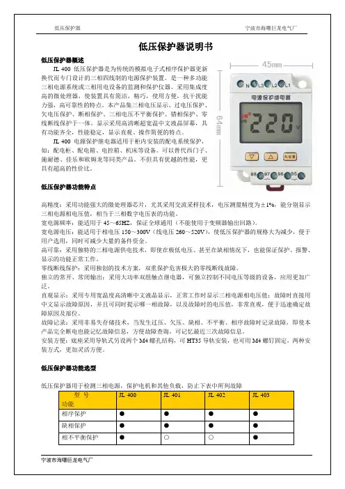
高精度:采用功能强大的微处理器芯片,尤其采用交流采样技术,电压测量精度为±1%,能分别显示
,保证全球通用(不能使用于变频器输出回路)。
,使低压保护器的规格大为减少,便于高可靠:采用独特的三相电源供电技术,即使在极低电压、甚至在缺相情况下,也能保证保护、报警、
相序保护器原理图
相序监测:当低压保护器通电时,如果相序正确并且所有三相带电,继电器吸合。
过欠压保护器原理
缺相保护器原理图
缺相检测:当缺相故障时,继电器断电。
正常工作(无故障)时继电器吸合。
当缺相时立即断电。
电压不平衡保护器原理图
A、B、C:“不平衡”字符闪烁D:“不平衡”字符长亮。
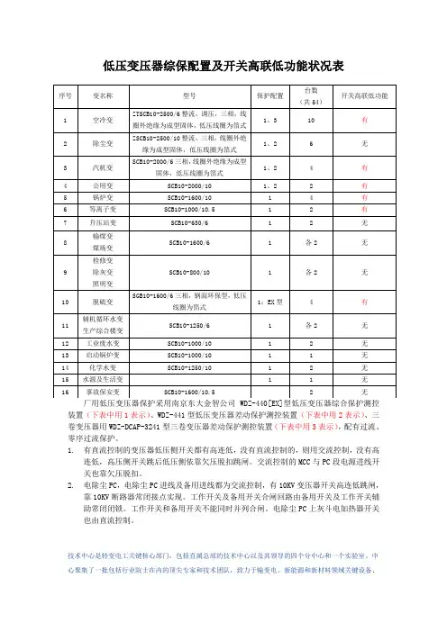
低压变压器综保配置及开关高联低功能状况表装置(下表中用1表示)、WDZ-441型低压变压器差动保护测控装置(下表中用2表示)、三卷变压器用WDZ-DCAP-3241型三卷变压器差动保护测控装置(下表中用3表示),配有过流、零序过流保护。
1.有直流控制的变压器低压侧开关都有高连低,没有直流控制的,则用交流控制,没有高连低,高压侧开关跳后低压侧依靠欠压脱扣跳闸。
交流控制的MCC与PC段电源进线开关也靠欠压脱扣。
2.电除尘PC,电除尘PC进线及备用进线都为交流控制,有10KV变压器开关高连低跳闸,靠10KV断路器常闭接点实现。
工作开关及备用开关合闸回路由备用开关及工作开关辅助常闭闭锁。
工作开关和备用开关不能同时并列合闸。
电除尘PC上灰斗电加热器开关也由直流控制。
技术中心是特变电工关键核心部门,包括直属总部的技术中心以及其领导的四个分中心和一个实验室。
中心聚集了一批包括行业院士在内的顶尖专家和技术团队,致力于输变电、新能源和新材料领域关键设备、技术、工艺和标准的研究与开发。
技术中心不断的开发出满足用户需求的新产品、新技术,同时也不断完善和改进现有技术。
中心的使命在于为不同国家、区域的用户提供可靠、节能、方便、适用的产品和新的可选择的技术方案,并降低用户的成本,与此同时使公司获得持续的竞争能力。
中心以全球化的视野,在输变电、新能源、新材料领域,与清华大学、中国科学院电工研究所、乌克兰扎布罗热变压器研究所、克罗地亚、西安交通大学等10余家令人尊敬的科研院校进行合作,与全球范围内的技术领先者交流和学习,开展技术引进、消化、吸收和再创新工作,不断使新的技术成果得以商品化,并促进了中国在输变电领域的重大装备国产化进程。
天津市特变电工变压器有限公司拥有天津市市级技术中心,该中心聚集了一批行业内知名技术专家和致力于干式变压器研究、开发的技术团队,拥有享受国务院特贴专家、高级工程师、工程师、助理工程师。
在全面引进、消化吸收了葡萄牙、德国等世界一流的技术及工艺的同时坚持自主研发,先后开发出20~20000KV、电压等级在35KV及以下的各种规格型号的环氧树脂胶主干式电力变压器、干式配电变压器、非晶合金干式变压器、整流变压器、接地变压器、消弧变压器、自动调谐消弧成套设备、H级系列变压器、电抗器、智能箱式变电站等十余个品种、上百个规格型号的标准和非标产品,并拥有SSC-10000/35三相三绕组干式电力变压器、ZQSCB-2500/35轨道交通用牵引整流机组、ZTSC-630~5000/6-18包封线圈的18脉波中压变频整流变压器、SCBH10-315/10节能性非晶合金干式变压器等一大批处于行业领先地位的先进技术。

TDR935系列变压器保护装置技术说明书南京钛能电气研究所文件名称TDR935系列变压器保护装置技术说明书文件说明无版本记录版本日期修改人说明V1.00 2008-03-26 崔得志初始版本V2.00 2008-04-22 崔得志重新修订TDR935系列变压器保护装置技术说明书V 2.00 2008.04编写:崔得志张慧刘明辉王海兵范汇华审核:姚卫兵批准:金启超2008年4月目录1.简介 (1)2.特点 (2)3.应用 (2)4.保护原理 (3)4.1.差动保护专题 (3)4.2.后备保护专题 (6)5.TDR935型变压器差动保护装置 (10)5.1.适用范围 (10)5.2.保护配置 (10)5.3.装置特点 (10)5.4.保护定值 (10)5.5.典型接线图 (13)6.TDR935A型变压器后备保护装置 (14)6.1.适用范围 (14)6.2.保护配置 (14)6.3.测控配置 (14)6.4.装置特点 (14)6.5.保护定值 (15)6.6.典型接线图 (17)7.TDR935B型变压器后备保护装置 (18)7.1.适用范围 (18)7.2.保护配置 (18)7.3.测控配置 (18)7.4.装置特点 (18)7.5.保护定值 (19)7.6.典型接线图 (21)8.TDR935D型变压器保护装置 (22)8.1.适用范围 (22)8.2.保护配置 (22)8.3.测控配置 (22)8.4.装置特点 (23)8.5.保护定值 (23)8.6.典型接线图 (25)9.辅助功能 (26)9.1.人机界面 (26)9.2.故障录波 (27)I9.3.顺序事件记录 (27)9.4.开关变位记录 (27)9.5.矢量显示 (27)9.6.DRS软件的支持 (28)10.用户接口 (29)10.1.面板及显示 (29)10.2.按钮 (29)10.3.通信接口 (30)10.4.口令保护 (30)11.技术数据 (31)11.1.额定直流电压 (31)11.2.额定交流数据 (31)11.3.功率消耗 (31)11.4.保护部分精度 (31)11.5.测控部分精度 (31)11.6.开关量输入 (31)11.7.输出容量 (32)11.8.通讯接口 (32)11.9.电气环境 (32)11.9.1.直流电源 (32)11.9.2.绝缘电阻 (33)11.9.3.介质强度 (33)11.9.4.冲击电压 (33)11.9.5.脉冲群干扰 (33)11.9.6.辐射电磁场干扰 (34)11.9.7.静电放电干扰 (34)11.9.8.快速瞬变干扰 (34)11.9.9.正常工作大气条件 (34)11.10.机械环境 (34)12.定货须知 ............................................................................................................................... 3513.附录 (36)附录1.装置面板布置图 (37)附录2.装置背板布置图 (37)附录3.装置安装尺寸图 (38)附录4.操作回路原理图 (39)附录5.工程用装置电原理图 (42)TDR935变压器差动保护装置 (42)TDR935A变压器后备保护装置 (45)TDR935B变压器后备保护装置 (48)TDR935D变压器保护装置 (51)附录6.变压器差动保护整定示例 (54)注意:产品的型号、功能、配置可能由于软件版本升级有所改变,请注意最新版本资料。

Visit our website at: Emailourtechnicalsupportat:******************************** When unpacking, make sure that the product is intactand undamaged. If any parts are missing or broken,please call 1-888-866-5797 as soon as possible.2020 by Harbor Freight T ools®. All rights reserved.No portion of this manual or any artwork contained herein may be reproduced in any shape or form without the express written consent of Harbor Freight T ools. Diagrams within this manual may not be drawn proportionally. Due to continuing improvements, actual product may differ slightly from the product described herein.ools required for assembly and service may not be included.Read this material before using this product. Failure to do so can result in serious injury. SAVE THIS MANUAL.Read all safety warnings, instructions, illustrations and specifications provided with this power tool. Failure to follow all instructions listed below may result in electric shock, fire and/or serious injury.1. WARNING: Risk of Electric Shock: Whenused outdoors, install only to a coveredClass A GFCI protected receptacle that isweatherproof, marked “Wet Location”, withthe power unit connected to the receptacle.If one is not provided, contact a qualifiedelectrician for proper installation. Ensure thatthe power unit and cord do not interfere withcompletely closing the receptacle cover.2. WARNING: Risk of Electric Shock: Installpower unit 5 feet (1.5m) or more from apool or spa and 10 feet (3.05m) or morefrom a fountain. Where the power unit isinstalled outdoors, connect power unit to areceptacle protected by a GFCI branch.3. Suitable for outdoor use only.4. Not for use with dimmers.5. Mount at least 1 foot (30cm) above ground.6. Do not connect two or more power supplies together.7. Do not use extension cords.8. For use with low voltage landscapelighting systems only.9. Use only with maximum 120W lamp load.10. Mount the power unit in or on non-combustiblemounting surfaces only.11. Main secondary wiring is intended for shallowburial - less than 6 inches (152mm).12. Not suitable for use with submersibleluminaries and pumps.13. Do not repair or tamper with the cord or plug.14. Do not submerge power unit in liquid.15. Do not connect light fixtures with power on.16. Assemble only according to these instructions.Improper assembly can create hazards.17. Wear ANSI-approved safety goggles andheavy-duty work gloves during assembly.18. Keep assembly area clean and well lit.19. Keep bystanders out of the area during assembly.20. Do not assemble when tired or when under theinfluence of alcohol, drugs or medication.21. This product is not a toy. Do not allowchildren to play with or near this item.22. Use as intended only.23. Inspect before every use; do not useif parts are loose or damaged.24. Maintain product labels and nameplates.These carry important safety information.If unreadable or missing, contactHarbor Freight Tools for a replacement.SAVE THESE INSTRUCTIONS.Page 2For technical questions, please call 1-888-866-5797.Item 57998GroundingTO PREVENT ELECTRIC SHOCK AND DEATH FROMINCORRECT GROUNDING WIRE CONNECTION:Check with a qualified electrician if you are in doubt as to whether the outlet is properly grounded.Do not modify the power cord plug provided. Never remove the grounding prong from the plug. Do not use the power unit if the power cord or plug is damaged. If damaged, have it repaired by a service facility before use. If the plug will not fit the outlet, have a proper outlet installed by a qualified electrician. Extension CordsNote: Extension cords must not be used with power pack.SpecificationsInput Rating120VAC / 60Hz / 1.2AOutput Rating12VAC / 10AMax Lamp120WWire16/2 16AWG/2-Conductor Low Voltage LandscapeItem 57998Page 3For technical questions, please call 1-888-866-5797.PhotoDisplayFunctionButtonsWhen used outdoors, install only to a covered Class A GFCI protected receptacle that is weatherproof, marked “Wet Location”, with the power unit connected to the receptacle. If one is not provided, contacta qualified electrician for proper installation. Ensure that the power unit and cord do not interfere with completely closing the receptacle cover. Do not plug in Power Cord until installation is complete. Landscape Wire SelectionThis data is provided as a general guideline.Calculate Lamp WattageThe Power Pack’s 120W circuit will power up to 96 watts of lights.Check wattage of individual light fixtures and add all wattage together. Do not exceed 96W total.Page 4For technical questions, please call 1-888-866-5797.Item 57998Page 5For technical questions, please call 1-888-866-5797.Item 57998InstallationWARNING! TO PREVENT SERIOUS INJURY: Verify that installation surface has no hidden utility lines before installing light fixtures.1. Place Power Pack close to GFCI outlet. Itmust receive maximum sunlight in order for photo sensor to work properly. 2. Lay Power Pack on its back on a sturdy surface.Do not plug in Power Pack.3. Connect Wires to Power Packa. Split conductors 2″, strip 3/4″ ofinsulation, twist strands together.b. Loosen screws. Insert each conductor under one screw. Screw connections must be tight. Do not mix solid and stranded type wires under one screw. Make sureinsulation clears Pressure Plate.4. Mount Power PackWARNING! TO PREVENT SERIOUS INJURY: Verify that installation surface has no hidden utility lines before drilling or driving screws.a. Using included template, mark and drill mounting holes.b. Insert two included anchors into the holes and two included screws into the anchors leaving about 1/4″ of threads exposed.c. Place large center of keyholes on back of Power Pack over screw heads and pull down gently to lock screws into keyholes. Do not plug in Power Pack.5. Install Light Fixturesa. Lay out light fixtures in desired locations. The first light fixture must be installed at least 10 feet from Power Pack.b. Lay out Landscape Wire from Power Pack along path of light fixtures.c. Install light fixtures, then connect to wire according to light fixture’s instructions.d. Bury wire no deeper than 6". 6. Plug in Power Cord. Do not usean extension cord.7. Press Up/Down buttons to scroll through menu.a. A = Auto - Dusk to dawn.b. 1 -9 = Hours on after dusk.c. O = Manual - On until manually turned off.Procedures not specifically explained in this manual mustbe performed only by a qualified technician.TO PREVENT SERIOUS INJURY FROM ACCIDENTAL OPERATION:Unplug the Power Pack from its electrical outlet before performing any procedure in this section.1. CLEAN PERIODICALLY with a damp towel.Do not clean with chemicals, solvents or harsh abrasives. Do not put too much pressureon the display or buttons while cleaning.2. WARNING! TO PREVENT SERIOUS INJURY: Ifthe plug or the supply cord is damaged, it mustbe replaced only by a qualified service technician.TroubleshootingPage 6For technical questions, please call 1-888-866-5797.Item 57998Record Serial Number Here:Note: If product has no serial number, record month and year of purchase instead.Note: Replacement parts are not available for this product. Refer to UPC 193175430588.Item 57998For technical questions, please call 1-888-866-5797.Page 7Harbor Freight Tools Co. makes every effort to assure that its products meet high quality and durability standards, and warrants to the original purchaser that this product is free from defects in materialsand workmanship for the period of 90 days from the date of purchase. This warranty does not apply to damage due directly or indirectly, to misuse, abuse, negligence or accidents, repairs or alterations outside our facilities, criminal activity, improper installation, normal wear and tear, or to lack of maintenance.We shall in no event be liable for death, injuries to persons or property, or for incidental, contingent,special or consequential damages arising from the use of our product. Some states do not allow the exclusion or limitation of incidental or consequential damages, so the above limitation of exclusionmay not apply to you. THIS WARRANTY IS EXPRESSLY IN LIEU OF ALL OTHER WARRANTIES, EXPRESS OR IMPLIED, INCLUDING THE WARRANTIES OF MERCHANTABILITY AND FITNESS.To take advantage of this warranty, the product or part must be returned to us with transportation charges prepaid. Proof of purchase date and an explanation of the complaint must accompany the merchandise.If our inspection verifies the defect, we will either repair or replace the product at our election or we may elect to refund the purchase price if we cannot readily and quickly provide you with a replacement. We will return repaired products at our expense, but if we determine there is no defect, or that the defect resulted from causes not within the scope of our warranty, then you must bear the cost of returning the product.This warranty gives you specific legal rights and you may also have other rights which vary from state to state.26541 Agoura Road • Calabasas, CA 91302 • 1-888-866-5797。

三相油浸式电力变压器安装使用说明书山东省金曼克电气集团股份有限公司目录一.概述 (1)二.适用范围及使用条件 (2)三.运输 (3)四.验收 (4)五.储存 (5)六.现场安装 (6)七.交接验收与试运行 (7)八.使用与维护 (8)一.概述我厂始建于1967年2月,是输变电电力变压器机电定点生产厂。
80年代初在我国首批生产S7(SL7)系列低损耗三相油浸式电力变压器以来,先后开发生产了S8、S9、S11等损耗更低的节能型系列产品,可生产容量31500KVA及以下、电压110KV及以下三相油浸式电力变压器,并可满足用户对矿用、电炉与潜油泵等特种变压器的需要。
本厂自1988年引进德国梅·克瑞斯特(May δ Christe)公司专有技术。
生产树脂浇注干式电力变压器以来,已形成了干式与油浸式两大系列产品,并分别形成了80万KVA的年生产能力,产品销往全国各地及东南亚等国。
本厂具有先进、完善与科学的变压器制造技术与设备,并具有相应的实验能力,除突发短路实验外可进行变压器出厂实验、型式试验与特殊试验的实验项目,凡经本厂生产的变压器出厂前均已全部通过国家有关标准规定的所有实验项目,因而确保了产品各项性能指标的稳定可靠。
为方便用户的安装与使用,本说明书提供了如下内容安装、使用与监护参考。
二、使用范围及使用条件1、本说明书适用与容量为31500KVA及以下、电压为110KV及以下的三厢油浸式电力变压器。
2、其他相同的容量、相同电压等级的油浸式变压器产品可参照本说明书执行。
3、正常使用的条件:①海拔不超过1000米;②环境温度:最高温度+40℃。
最高日平均温度+30℃。
最高年平均气温20℃。
最低气温-30℃。
③电源电压的波形:电源电压的波形近似正弦波:④三相电源变压的对称:三相变压器所连接的电源电压应近似对称:⑤特殊使用条件:用户应在询价单中详细提出在正常使用条件中尚未包括的使用条件,由制厂与用户协商确定。
NAS9210系列保护装置技术手册编写:金启超NAS9213A型综合保护装置技术手册南京南自电力控制系统工程有限公司目录版本2.0 ,20050620NAS9213A型综合保护简介 (4)适用范围 (4)保护配置 (4)测控配置 (5)保护特点 (5)应用说明 (5)35kV及以下线路保护 (5)35kV及以下线路变压器保护 (6)35kV及以下线路电容器保护 (6)10kV及以下高压电动机保护 (6)35kV及以下变压器后备保护 (7)装置说明 (8)定值表 (8)遥信表 (9)遥测表 (11)遥控表 (12)NAS-9213A综合保护装置典型接线图 (13)附录A 保护原理说明 (14)充电保护 (14)NAS9213A型综合保护简介适用范围NAS9213A是适用于35kV及以下电压等级的线路、电容器、电动机、变压器保护等设备的综合保护及测控装置。
本装置采用三相式保护CT构成三相式保护,两相式测量CT实现遥测功能,具有较高的测量精度,本保护不设零序过压保护。
保护配置☑四段式复合电压闭锁过流保护◆I、II、III段动作于OUT101和OUT102◆IV段动作于OUT104☑零序过流保护◆告警或动作于OUT101和OUT102☑加速段保护◆动作于OUT101和OUT102☑过负荷保护◆告警☑重合闸◆动作于OUT103☑低电压保护◆动作于OUT101和OUT102☑过电压保护◆动作于OUT101和OUT102☑充电保护◆动作于OUT101和OUT102☑非电量保护◆告警或动作于OUT101和OUT102☑TV断线监视☑开关位置监视☑告警、事故事件记录☑故障录波☑故障分析软件(选配)☑四段式复合电压闭锁过流保护测控配置☑10路开关量采集电路,64路遥信信号及相关的SOE信号☑8路模拟量采集(Uab、Uac、Ia、Ic、IA、IB、IC、3I0)☑遥控断路器的分合闸;☑电压、电流、功率、功率因数、频率等模拟量的遥测;保护特点☑三相式保护,三相保护CT接入☑两相式测控,独立测量CT接入☑两路可整定延时的非电量保护☑各保护功能均可选择投入或退出☑可存贮多达16套保护定值,定值切换可在线实现☑装置中保护、测控用CT独立配置,遥测精度高☑可实现集散式小电流接地选线功能☑可升级软件☑故障录波存储4条☑高质量图形液晶模块128×64☑进口继电器输出☑LCD显示矢量应用说明35kV及以下线路保护☑三段式复合电压闭锁电流保护☑IV段过流用于选跳☑重合闸☑加速段保护☑低频保护☑零序电流保护☑接地告警(零序过压保护)☑过负荷保护(告警)☑充电保护35kV及以下线路变压器保护☑三段式复合电压闭锁电流保护☑IV段过流用于选跳☑重合闸☑加速段保护☑低频保护☑零序电流保护☑接地告警(零序过压保护)☑过负荷保护(告警)☑非电量保护35kV及以下线路电容器保护☑三段式复合电压闭锁电流保护☑过电压保护☑低电压保护☑不平衡电流保护或零序电流保护☑不平衡电压保护或接地告警☑过负荷保护(告警)☑非电量保护10kV及以下高压电动机保护☑三段式复合电压闭锁电流保护☑过电压保护☑低电压保护☑零序电流保护☑接地告警(零序过压保护)☑过负荷保护(告警)☑非电量保护35kV及以下变压器后备保护☑三段式复合电压闭锁电流保护⏹I、II段保护为总后备,动作于两侧开关⏹III段保护动作于两侧开关⏹IV段保护动作于低压母联☑零序电流保护⏹告警或动作于两侧开关☑接地告警(零序过压保护)⏹告警☑过负荷保护(告警)☑非电量保护注:1.电流保护配置选跳时,设置一段两时限,在使用时,可将III段保护的电流定值和IV段保护的定值设置为相同的值,实现选跳母联断路器。
Eaton MPN8403LEAXX2QEaton Magnum low voltage power circuit breaker, Magnum PXR,Double narrow frame, 4000 A (ABCABC), 85 kA, Three-pole,Drawout horizontal mounting, PXR25 LSIAM trip unitGeneral specificationsEaton Magnum low voltage power circuitbreakerMPN8403LEAXX2Q78668960890316.3 in16.8 in24.9 in177 lbCCC Marked CE Marked SABA Listed NEMA Compliant CSA CertifiedKEMA CertifiedLloyd's Register Certified UL ListedANSIABS CertifiedDNV GL CertifiedProduct Name Catalog NumberUPCProduct Length/Depth Product Height Product Width Product Weight Compliances CertificationsDouble narrow Three-pole Magnum PXRDouble narrow Magnum PXR25 LSI ARMSThree-pole4000 A85 kAIC85 kAIC4000 AZone selective interlocking application paper Magnum circuit breakers with Power Xpert Release trip units product aid Selevctive coordination application paper - IA0120000E3Magnum PXR and PD-SB standard and narrow frame UL Certificate of ComplianceMagnum PXR and PD-SB double and double narrow frame UL Certificate of ComplianceMagnum PXR low voltage power circuit breakers user manual Microsoft Word - Power Xpert Protection Manager Quick Start Guide.docxPower Xpert Release trip unit for Magnum PXR circuit breakers PXRFrame Number of poles TypeFrame Series Trip TypeNumber of poles Rated uninterrupted current (Iu)Interrupt rating Interrupt rating Rated uninterrupted current (Iu)Application notesBrochuresCatalogsCertification reportsManuals and user guidesEaton Corporation plc Eaton House30 Pembroke Road Dublin 4, Ireland © 2023 Eaton. All Rights Reserved. Eaton is a registered trademark.All other trademarks areproperty of their respectiveowners./socialmedia20/25 user manualPower Xpert Protection Manager x64 22.6 1 Power Xpert Protection Manager x32 22.06 1 Eaton Specification Sheet - MPN8403LEAXX2Q Low voltage circuit breakers guide spec Magnum PXR 20/25 electronic trip units time current curves Safer by design: arc energy reduction techniques Cyber security white paperMolded case and low-voltage power circuit breaker healthSoftware, firmware, and applications Specifications and datasheetsTime/current curvesWhite papers。
12Tran s f or me r sLow Voltage Products & Systems12.1TransformersDescription• Epoxy encapsulated coils up through 750VA • Epoxy resin impregnated coils 1 kVA to 5 kVA• Provides stepped down voltages formachine tool control devices and industrial control panels• Laminations of high quality silicon steel • Minimum core loss• Optimized performance• Copper magnet wire providing the highest quality and efficient operation • Molded-in terminals• 80°C rise, 130°C insulation system • 50/60 Hz• UL File # E175311• CSA File #LR27533• IP 20 Touch safe covers available as an optionT r a n s f o r m e r s12.2Low Voltage Products & Systems1 Consult factory for applications with different voltages.2 Whenever both secondary voltages are to be used at the same time, remove the secondary fuse clip and use a separate mounted 2 pole fuse block.3 Includes terminal and fuse covers.T - Industrial control transformer X - New generation industrial control transformer Primary voltage rating 14 - 460V , 230V & 208V 6 - 575V & 600VVA rating045 = 45VA 350 = 350VA 050 = 50VA 500 = 500VA 075 = 75VA 750 = 750VA 100 = 100VA 1K = 1000VA 150 = 150VA 1.5K = 1500VA 200 = 200VA 2K = 2000VA 250 = 250VA 3K = 3000VA 300 = 300VA 5K = 5000VAX 4 100 PS F1 /COption 3Add $15 to list priceIP 20 Terminal coversMeets finger safe or touch safe requirements for IEC specification 529. Available 50VA thru 750VA Secondary voltage(s) 2F = 24V 1 = 115VF1 = 115/24V dual secondary 2Fuse blocksP = primary fuse block (2 pole Class CC, less fuses)S = secondary fuse clip (13/32" x 1 1/2", less fuse)Example : T4100PSF1• ABB Industrial control transformer• Primary voltage: 460V , 230V and 208V • 100 VA rating• Primary & secondary fuse blocks provided • S econdary voltage 115/24V • Optional IP 20 terminal coversLow Voltage Products & Systems12.5Primary voltage — 460/230/208V , 480/240V , 440/220/200V Secondary voltage — 115/24V 2, 120/25V , 110/23VPrimary voltage — 460/230/208V , 480/240V , 440/220/200V Secondary voltage — 115V , 120V , 110V1 Primary & secondary fuse block provided as standard (750VA unit, only).2 Whenever both secondary voltages are to be used at the same time, remove the secondary fuse clip and use a separate mounted 2 pole fuse block.Discount schedule ATSide ViewSide ViewT op View Side ViewX4045SF1T41K1X4750PSF112.6Low Voltage Products & SystemsPrimary voltage — 600/575/550V Secondary voltage — 120/115/110VPrimary voltage — 575/460/230V Secondary voltage — 115 - 95VDiscount schedule ATT op ViewSide ViewT op View Side View。
/switchgearSwitchgear Instruction and Installation GuideType 2B Arc Resistant WL Low Voltage Metal-Enclosed SwitchgearIMPORTANTThe information contained herein is general in nature and not intended for specific application purposes. It does not relieve the user of responsibility to use sound practices in application, installation, operation, and maintenance of the equipment purchased. Siemens reserves the right to make changes in the specifications shown herein or to make improvements at any time without notice or obligations. Should a conflict arise between the general information contained in this publication and the contents of drawings or supplementary material or both, the latter shall take precedence.NOTEThese instructions do not purport to cover all details or variations in equipment, nor to provide for every possible contingency to be met in connection with installation, operation, or maintenance. Should further information be desired, or should particular problems arise which are not covered sufficiently for the purchaser’s purposes, the matter should be referred to the local Siemens sales office.The contents of this instruction manual should not become part of or modify any prior or existing agreement, commitment, or relationship. The sales contract contains the entire obligation of Siemens Industry, Inc. The warranty contained in the contract between the parties is the sole warranty of Siemens Industry, Inc. Any statements contained herein do not create new warranties or modify the existing warranty.2Switchgear Instruction and Installation Guide Type 2B Arc Resistant WL Low Voltage Metal-Enclosed Switchgear Table of ContentsIntroduction and SafetyIntroduction 4Qualified person 4Signal words 4Dangerous procedure 4Field Service Operation 4General DescriptionIntroduction 5Scope 5General Description 5Special FeaturesSwitchgear – Rear 6Switchgear – Front 7Breaker Compartment 7Auxiliary Compartment 8Bottom Compartment Breaker Cradle 8Riser Base 8InstallationDimensional Data for Rear Connected Arc Resistant Switchgear 9 - 12Arc Resistant Gear with Overhead Plenum 13Dimensional Data for Front & Rear Connected – Wall Mounted 14 - 15Dimensions – Floor Mount (Requires Rear Access) 16Switchgear Dimensions – Side View (Without Overhead Plenum) 17Dimensions – Incoming Section – Cable Entry Top 18Dimensions – Incoming Section – Cable Entry Bottom 19Dimensions – Left Incoming Section – Sentron Busway Top and Bottom 20Dimensions – Right Incoming Section – Sentron Busway Top and Bottom 21Dimensions – Feeder Cable Section (Area) – Cable Entry Top 22Dimensions – Feeder Cable Section (Area) – Cable Entry Bottom 23Installation Instructions for Overhead Plenum 24 - 273Switchgear Instruction and Installation GuideIntroductionType 2B Arc Resistant WL low voltage switchgear is designed to meet all applicable UL, ANSI, NEMA and IEEE standards.It is designed and performance tested to ANSI C37.20.7 to provide an additional degree of personnel protection from internal arcing faults. Successful application and operation of this equipment depends as much upon proper installation and maintenance by the user as it does upon the careful design and construction by Siemens.The purpose of this Instruction Manual is to assist the user in developing safe and efficient procedures for the installation, maintenance and use of the equipment. This Instruction Manual acts a supplement to Siemens Rear and Front Connected Type WL Low Voltage Switchgear Instruction and Installation Guides.Application of Arc Resistant Low Voltage Switchgear meeting the requirements of IEEE C37.20.7 does not eliminate the requirements of Personal Protection Equipment (PPE). Contact the nearest Siemens representative if any additional information is desired.Qualified PersonFor the purpose of this manual and product labels, a Qualified Person is one who has the skills and knowledge related to the construction and operation of the electrical equipment and installations and has received safety training to recognize and avoid the hazards involved. In addition, this person has the following qualifications:• Training and authorization to energize, de-energize, clear, ground and tag circuits and equipment in accordance with established safety practices.• Training in the proper care and use of protective equipment such as rubber gloves, hard hat, safety glasses, faceshields, flash clothing, etc., in accordance with established safety procedures.• Training in rendering first aid. Signal WordsThe signal words “Danger,” “Warning” and “Caution” usedin this manual indicate the degree of hazard that may be encountered by the user. These words are defined as:Danger – Indicates an imminently hazardous situation which if not avoided, will result in death or serious injury.Warning – Indicates a potentially hazardous situation which, if not avoided, could result in death or serious injury.Caution – Indicates a potentially hazardous situation which, if not avoided, may result in minor or moderate injury Dangerous ProceduresIn addition to other procedures described in this manual as dangerous, user personnel must adhere to the following: 1. Always work on de-energized equipment. Alwaysde-energize a breaker and remove it from the switchgear before performing any tests, maintenance or repair.2. Always discharge energy from closing and opening(tripping) springs before performing maintenance on circuit breakers.3. Always let an interlock device or safety mechanismsperform its function without forcing or defeatingthe device.Field Service OperationSiemens Industrial Services Division can provide the following support services for Type WL low voltage switchgear.Call 1-800-333-7421 to obtain additional information and schedule an appointment.• Start-up and Commissioning• Component and System Testing• Maintenance (Scheduled and Preventative)• Repair and Refurbishing• On Site Operational TrainingType 2B Arc Resistant WL Low Voltage Metal-Enclosed Switchgear Introduction and Safety4Switchgear Instruction and Installation GuideIntroductionSiemens Type 2B Arc Resistant Metal-Enclosed Low Voltage Switchgear is designed to provide an additional degree of protection for personnel performing normal operating duties in proximity to the energized equipment. Such duties include opening or closing breakers, closed door racking of breakers, reading of instruments, or other such activities that do not require the opening of doors or removal of covers except doors or covers of compartments specifically identified aslow-voltage control or instrumentation compartments. It is designed and performance tested to ANSI C37.20.7 to provide an additional degree of protection from internal arcing faults. Should additional information be desired, including replacement instruction books, contact yourSiemens representative.ScopeThese instructions cover the installation and maintenanceof Siemens Type 2B WL Arc Resistant metal enclosed low voltage switchgear assemblies, using the Type WL UL -1066 low voltage power circuit breakers. A typical indoor Type 2B WL arc resistant switchgear assembly is shown in Figure 1.This instruction manual acts as a supplement to Siemens Rear and Front Connected Type WL Low Voltage Switchgear Instruction and Installation Guides. This manual discusses the special features and maintenance associated with arc resistant switchgear.General DescriptionType 2B Arc Resistant WL switchgear is an assembly of an indoor enclosure and mounting base with arc plenum. It has an insulated bus bar system, removable rear cover panels/ doors secured with captive screws, section barriers and cable compartment barriers. (Sections Barriers & Cable compartment barriers are Optional for FC). Flame retardant barriers and shutters are provided in power circuit breaker compartments. One piece circuit breaker compartment doors with insert panels for fuses, indicating lights and control switches are used when required.The following must be maintained for proper functioning of Arc Resistant switchgear. 39” (990) minimum front aisle (FS3 4 Pole breaker require 42” [1066] minimum), and 36” (914) minimum rear aisle (Rear Connected only). Working space requirements around electrical equipment are specified in the National Electrical Code® (NEC 110.26 2017). Minimum Ceiling Height Requirement 36” (900) above vent stack (NEC 408.18 2017):136” (3454) – Arc Resistant switchgear WITHOUT Overhead PlenumAlternate Manufacturer’s Requirement 18” (457)above vent stack (For Non-Combustible* Ceiling)118” (2997) – Arc Resistant switchgear WITHOUTOverhead Plenum120” (3048) – Arc Resistant switchgear WITHOverhead Plenum*Non-Combustible as defined by AHJ and/or NECThe arc resistant ratings are listed on the switchgearrating label. Ratings are given for:(1) Accessibility Type,(2) Arcing SHORT-CIRCUIT current and voltage, and(3) Arcing duration.Type 2B Arc Resistant WL Low Voltage Metal-Enclosed SwitchgearGeneral DescriptionFront view of switchgear.56Switchgear Instruction and Installation GuideRear Isometric view of Front Connected SwitchgearTop cover plate pressure relief flaps (Rear Connected)• The top cover flaps are applicable with Arc Resistant Construction without Overhead Plenum• These flaps are closed under normal conditions.• The flaps open outward in the event of an arcing fault to relieve internal pressure.• The opening of flaps should not be blocked by cables, conduits, bus duct, etc.• A clear space of 22” must be maintained above the flaps. Rear cover pressure dams (Rear Connected)• All the vents in the rear side of switchgear have pressure dam flaps installed inside.• During normal operation the flaps should be open by 2” to 3” for venting.• These flaps close in the event of arcing fault to prevent arc gases from exiting the rear of the equipment.• The flaps should not be modified, removed or blocked open.Enclosure and Rear Covers (Rear and Front Connected)• Reinforced enclosure to withstand pressure from internal arcing faults.• Reinforced bolted rear covers/doors.• Ensure that all screws are in place and tightenedTop vent stack pressure relief flaps (Front Connected)• The flaps are applicable with Arc Resistant Construction without Overhead Plenum.• These flaps are closed under normal conditions.• The flaps open outward in the event of an arcing fault to relieve internal pressure.• The opening of flaps should not be blocked by cables, conduits, bus duct, etc.Type 2B Arc Resistant WL Low Voltage Metal-Enclosed SwitchgearSpecial FeaturesSwitchgear – RearRear Isometric view of Rear Connected Switchgear7Switchgear Instruction and Installation GuideSwitchgear – FrontBreaker CompartmentFront view of SwitchgearFront View of Breaker CompartmentFront view of Breaker CompartmentEnhancements• Reinforced and gasketed front doors with additional hinges and latching means. Ensure that all doors are properly secured before placing gear in service.•placed back into service.• be installed under the switchgear.Type 2B Arc Resistant WL Low Voltage Metal-Enclosed SwitchgearSpecial FeaturesBreaker compartment partsBreaker compartment gap protection parts provide protection in the event of arcing fault.Flame Retardant parts are attached on the back of metal gap protection partsThese parts must be in place during normal operation.If they are removed during installation or servicing, they must be replaced before gear is energized.8Switchgear Instruction and Installation GuideAuxiliary compartmentRiser BaseFront view of Riser BaseAuxiliary compartment parts• Auxiliary bucket gap protection parts provide protection in the event of arcing fault.• Flame Retardant parts are attached on the back of metal gap protection parts.• These parts must be in place during normal operation.• If they are removed during installation or servicing, they must be replaced before gear is energized.Gap between Switchgear and Riser Base• The gap between the Mounting Base and the Switchgear must be closed after installation with silicone caulking compound. Silicone caulking compound is installed at the factory if the switchgear is shipped installed on the Mounting Base. If the Mounting Base is shipped separately, a tube of silicone caulking compound is furnished withthe switchgearBreaker Cradle Button Plug• The button plug must be replaced after installing or servicing anchor bolt.• This part must be in place during normal operation.Bottom Compartment Breaker CradleIsometric view of D-CompartmentIsometric view of Auxiliary CompartmentType 2B Arc Resistant WL Low Voltage Metal-Enclosed SwitchgearSpecial featuresSwitchgear Instruction and Installation GuideSwitchgear Instruction and Installation Guide1213Dimensional Data for Front and Rear Connected Arc Resistant Gear with Overhead Plenum10.0Front View: WL Arc Resistant Switchgear with Overhead PlenumNote: Dimensions shown in inches and (mm). Drawings are not to scale.1. 118 (2997) minimum room ceiling height is required for ventilation of arc products for LV Arc resistant switchgear without overhead plenum.2. 120 (3048) minimum room ceiling height is required for LV Arc resistant switchgear with overhead plenum.3. Custom designed exhaust duct is provided when the exit is towards the front to clear the overhead hoist. Cross-sectional area of the exhaust duct remains same as shown in figure. Wall cutout required is same at 104 (2641) from floor.4. Siemens to provide weatherproof box to be installed outside the exterior wall over the exhaust duct exit.5. The area outside the exhaust duct vent needs to be kept clear of personnel and equipment due to the potential for pressurized exhaust gasses being expelled in the area as a result of arcing fault in the switchgear. An area of 4 feet X 4 feet centered on exhaust duct vent needs to be clear at all times.6. Exhaust duct is not self-supporting, recommended support every 6 linear feet minimum. The duct supports are not supplied by Siemens and must be supplied by the purchaser or the installing contractor.7. LV Arc Resistant switchgear with and without overhead plenum is to be installed on a solid surface to maintain the arc ratings. Consult factory for site conditions where a solid floor is not an option.Typical Drop Rod/Unistrut trapeze hanger arrangement shownExhaust DuctUnistrut5.0(127)2.1 (53)3.0 (76)Space for secondaryleads from above. Available onSections with removable conduit plate. Not available with Overhead PlenumoptionSpace for secondary leads from above & below.Above: All Sections2.0 (51)1.0 (25)7.0(179)(2) Holes for .50 (12mm)Grade 5 anchor bolts(Not furnished with equipment) 0.5 (13)Rear Space for secondaryleads from below: Breaker sections 5.0 (127) Space for secondary leads from above. Available on Sections with removable conduit plate. Not available with Overhead Plenum option2.0 (51)1.0 (25)2X for” anchors 0.5 (13)Front ViewRiser Base4.0 (102)2X for anchors38.0 (965) Anchor Bolt5.0(127) Space for secondaryleads from above.Available on Sections withremovable conduit plate.Not available withOverhead Plenum option1.0 (25)2.0 (51)Space for secondaryleads from below:Breaker sections4X for”anchorsFront Compartment BusCompartment30 (762) MinimumAisle Spacerecommended forFloor Mount BracketsinstallationRear Floor Mount(optional)0.5 (13)Maximum available conduit space at Top27.5 (699)2.25 (57) Typ13.9 (353)15.9 (404)Front Plan ViewFig - 5 RearW = 32 Section Width1.75 (44) Typ.Front Plan ViewFig- 614.5 (368)28.5 (724) Available conduit space at BottomAvailable Bottom Conduit Area when Lineup has Center Incoming and Sectionincludes a Bottom Through Bus16.2 (411)10 (254)Additional Space: 28.5 (724) X 10 (254)When Lower Auxiliary Compartment NOT present13.65 (347)21 (533)8.75 (222)Not Available at 4000A & 5000A: 28.5(724) X 5(127)5 (127)RearFront13 (330)22.4 (569)Plan View15.5 (394)D RearBusway Phase Orientation (ØA, ØB, ØC, N Front to Back)ØAØBØCN Cut-out area at Top. Bottom is open.14 (356)Fig- 7ESentron Busway Plug Rating (Cu)D 22 (559)RearCut-out area at Top. Bottom is openFront Plan ViewFig- 8GF13 (330)15.5 (394)Busway Phase Orientation (ØA, ØB, ØC, N Front to Back)ØAØBØCN 22.4 (569)14(356)Sentron Busway Plug Rating (Cu)F 22 (559)Maximum available conduit space at TopHSection Width W = 22, H = 17.5 (445) Section Width W = 30, H = 25.5 (648) Section Width W = 40, H = 35.5 (902)WSection Width2.25 (57) Typ.RearFront Plan View13.9 (353)15.9 (404)Fig- 9Available conduit space at BottomFront 1.75 (44) Typ.Additional conduit space available when Compartment D breaker not presentJSection Width W = 22, J = 18.5 (470) Section Width W = 30, J = 26.5 (673) Section Width W = 40, J = 36.5 (927) 25 (635) 3.7 (94)6.5 (165)11.75 (298)Not Available at 4000A & 5000A:J X 5(127)5 (127)RearPlan View Fig- 1024Switchgear Instruction and Installation GuideType 2B Arc Resistant WL Low Voltage Metal-Enclosed SwitchgearInstallation Instructions for Overhead PlenumOverhead Plenum assembly over the Switchgear section consists of two main components as shown:Plenum Vent Stack Front Iso View – End SectionSection PlenumA. Installation of Plenum Vent stack to the Switchgear sectionPlenum Vent Stack attaches to the Left and Right Lifting-Eye plate tab holes.Lifting eye plate25Switchgear Instruction and Installation GuideB. Installation of Section Plenum to the Switchgear sectionType 2B Arc Resistant WL Low Voltage Metal-Enclosed SwitchgearInstallation Instructions for Overhead PlenumFront Iso View – End SectionAdjacent SectionSection Plenum attaches to the Plenum Vent Stack.Slide the adjacent Section Plenums in the splice groove.Attach the Section Plenum to the Vent Stack.26Switchgear Instruction and Installation GuideC. Installation of Section Plenum when Duct Exit is Rear/Front of the Switchgear sectionD. Installation of Exhaust Duct to the Switchgear sectionType 2B Arc Resistant WL Low Voltage Metal-Enclosed SwitchgearInstallation Instructions for Overhead PlenumThe blow open trap doors need to align with the direction of exit path if front or rear duct is usedSlide the Exhaust Duct in the splice groove and attach toSection Plenum27Switchgear Instruction and Installation GuideE. Installation of End Exhaust Duct section Type 2B Arc Resistant WL Low Voltage Metal-Enclosed SwitchgearInstallation Instructions for Overhead PlenumOutside of BuildingOutside of BuildingInside ofBuildingInside ofBuildingExhaust Duct End Section10.05.50Exterior Wall of BuildingExhaust Duct End Section and Exterior Wall of Building ShownWeatherproof AssemblyCalk allCalk allseamsLeft ViewLeft ViewIsometric ViewIsometric ViewNote:1. The exhaust duct end section must not be extended more than 10 inches outside the building for proper functioning of exhaust flap when weather proof assembly is installed over the exhaust duct.Notes:1. The weatherproof assembly must be mounted 5.50 inches above theexhaust duct section for proper functioning of exhaust flap.2. The weatherproof assembly can extend up to 10 feet.Weatherproof SectionPublished bySiemens Industry, Inc. 2019.Siemens Industry, Inc.5400 Triangle ParkwayNorcross, GA 30092For more information, please contactour Customer Support Center.Phone: 1-800-241-4453E-mail: *******************/switchgearOrder No.: LVIM-ARCII-1019 BA(Siemens Internal Part Number 11-C-9887-01Rev. 2)Printed in U.S.A.© 2019 Siemens Industry, Inc.The technical data presented in this document is based on an actual case or on as-designed parameters, and therefore should not be relied upon for any specific application and does not constitute a performance guarantee for any projects. Actual results are dependent on variable conditions. Accordingly, Siemens does not make representations, warranties, or assurances as to the accuracy, currency or completeness of the content contained herein. If requested, we will provide specific technical data or specifications with respect to any customer’s particular applications. Our company is constantly involved in engineering and development. For that reason, we reserve the right to modify, at any time, the technology and product specifications contained herein.。
A continuously energized transformer needs periodic cleaning and maintenance to remove accumulations of dust or dirt from cooling ducts and other surfaces. Large accumulations may reduce cooling efficiency and lead to overheating. Cleaning and maintenance are recommended at least once a year in relatively clean installations and at more frequent intervals in more heavily contaminated atmospheres.Transformers that are de-energized for long periods of time generally require more frequent maintenance and cleaning to ensure removal of contamination. CleaningAccumulation of dirt on insulating surfaces becomes a hazard when a considerable amount of moisture is absorbed. Vacuuming is the recommended method for cleaning. Special attention should be given to cooling ducts within the winding. Low-pressure dry air can be used if care is taken to avoid driving the contamination into the insulation.—TR ANSFORMERSLow Voltage Dry Type TransformersCleaning and maintenance tips to keep your transformers in optimal conditionUnder normal environments and operating conditions, dry type transformers are virtuallymaintenance free. However, they do require occasional internal cleaning, care and inspection. The frequency of inspection, cleaning and care will depend on the atmospheric and/or environmental conditions at where the transformer is installed.Moisture is detrimental to most insulation systems. It is advisable to dry out any transformer that has been exposed for long periods of time to high humidity.Whenever moisture is visible on insulation surfaces, the unit must be dried before being energized. If moisture is evident, the unit should be dried out by placing it in an oven, by blowing heated air over it, or by placing strip heaters under the coil windings. The temperature of the heated air should not exceed 110C/230F. If strip heaters are used, the elements should not be allowed to come in contact with the transformer. Heat should be applied to both the front and rear of thetransformer. Transformers may be subjected toflooding, direct rain or similar applications of water. In such cases, normal drying techniques may not be adequate and the factory should be consulted as the transformer will most likely need to be replaced.MaintenanceMaintenance would include dust removal and/or drying (if applicable), tap changing, tightening of bolted connections, general servicing and inspection of auxiliary devices. Additional information related to the installation and maintenance of general purpose transformers can be found in ANSI publication C57.94, “Guide for Installation and Maintenance of Dry Type Transformers”.Contact your local ABB representative for more information.—We reserve the right to make technical changes or modify the contents of thisdocument without prior notice. With regard to purchase orders, the agreed particulars shall prevail. ABB Inc. does not accept anyr esponsibility whatsoever for potential errors or possible lack of information in this document.We reserve all rights in this document and in the subject matter and illustrations contained therein. Any reproduction, disclosure to third parties or utilization of its contents—in whole or in parts—is forbidden without prior written consent of ABB Inc. C opyright© 2020 ABB.All rights reserved.—ABB305 Gregson Drive Cary, NC 275111T Q C 1932E 0003 R E V .A J U L 2020Maintenance: ABB’s Low VoltageQL Dry Type Transformers meet modern efficiency standards and are designed forgeneral purpose lighting and electrical, motors, resistance heating and motor generators (without solid-state drives) applications. Our transformers allow faster installation, easier wiring and enhance safety.。
JL7.5-14-0704NS913低压变压器保护测控装置调试大纲及调试记录版本:V1.1装置编号调试日期调试人员质检人员南京南自科技发展有限公司南京南自电气科技有限公司2007年6月版本声明本调试大纲适用于软件版本V4.43,与之相对的软件与硬件信息如下:调试大纲版本修改记录检验报告总表1.通电前检测1.1外观检查外观检查内容如下:a.机箱表面无碰伤;b.油漆喷塑均匀、色泽无差异;c.印制线路板干净、无助焊剂;d.键盘接触可靠;e.指示灯布置整齐、液晶窗口无划痕。
本项结论:1.2参数检查对照装置铭牌,检查下列内容:a) 检查电源模块,电源输入电压与铭牌一致;开入量回路电阻选用与电源电压相符;b) 检查继电器模块,与本型号保护装置相符合,继电器回路以及开入量回路电阻选用与电源电源相符。
c) 检查继电器模块上元件方向,特别注意二极管方向正确。
如果调试前无特殊要求,J1(2.3)应插入短接,即TWJ继电器在印制板上直接与HQ(X6-6)端子相短接;如果用户要求TWJ单独由X6-2端子输出,则用镀银的铜丝将J1(2,3)断开。
本项结论:合格1.3 CPU模块检测对照印刷电路板,检查下列内容:a.元器件方向、位置焊接正确,特别检查钽电容焊接方向正确、U01(TMS320F206)DSP器件管腿之间无短路;b.测量+5V;5VGND;A VDD(+5V)、A VSS(-5V)与AGND;-12V与AGND;+24V与24VGND电源回路无短路;c.J5应插入短接帽短接,J1、J2程序固化插入短接帽短接,其余短接块插入短接帽但不短接。
本项结论:1.4装置接地检测测量装置接地端子X1-3与机箱上、下、左、右、前、后各部分电阻,阻值应小于0.5欧姆。
本项结论:合格2.绝缘、耐压检验2.1绝缘性能测量各输入、输出回路对地以及各输入、输出回路之间的绝缘电阻,其阻值应大于100MΩ.本项结论:合格2.2耐压性能在强电回路对地以及强电回路之间施加2000V漏电流为5mA的工频电压、历时1分钟,要求无闪烁、击穿现象。