BPW车轴使用说明书
- 格式:pdf
- 大小:29.83 MB
- 文档页数:44


挂车使用说明书 Company number:【WTUT-WT88Y-W8BBGB-BWYTT-19998】目录前言 (2)一、车辆外型图20英尺双轴骨架/FJZ9280TJZG40英尺双轴骨架/FJZ9350TJZG 40英尺双轴骨架/FJZ9400TJZG40英尺三轴平板/FJZ9380TJZP双轴低平板/FJZ9230TDP双轴低平板/FJZ9280TDP40英尺三轴平板/FJZ09280TP13米三轴栏板/FJZ9390TLP二、车辆主要技术参数钢板弹簧片数7/7,8/8 7/7,8/8 7/7/7,8/8/87/7/7,8/8/8车辆识别代码Vl N三、车辆主要结构1.车架1)车架由两根低合金钢板焊成“T”字型纵梁与一组横梁组合而成,是支承载荷的主体结构。
2)车架前部下面有与牵引车连接的牵引销和牵引板,牵引销主要用来传递牵引力或制动力,牵引板用来传递垂直方向的重力。
3)为了使集装箱锁栓在车架上,在车架的相应位置设有集装箱旋锁装置。
4)车架前端装有气管接头和电气连接的七孔插座。
2.锁栓装置为了使集装箱锁栓固在半挂车上,在车架的相应位置设有集装箱旋锁装置,该装置锁扣集装箱角件的有关尺寸均按IS0及国标制造。
旋锁的锁杆用优质钢模锻,有较高的抗拉强度,各配合处运转灵活,操作方便。
车架四角为固定式旋锁,中置为伸缩可藏式或倒卧可藏式旋锁,锁栓装置结构形式很多。
3.备胎升降器本系列半挂车设有悬链式备胎升降器,其作用是将备胎紧固在车架的下方。
为更换车轮提供方便。
其形式很多,常用的链式采用了一齿差式传动。
升降器的体积小,重量轻,简单而使用方便。
4.防护栏设有侧防护栏和后保险防护杠,以保证车辆行驶安全。
在车轮上方设有轮罩,在车轮后方设有挡泥板。
5.车轴、轮胎、钢圈1、制动蹄片2、制动蹄3、外轴承4、内轴承5、回位弹簧6、凸轮轴7、制动摇臂制动摇臂车轴由轴体、轴头、轮彀、制动器等组成、车轮由轮胎、轮辋、联接螺栓等组成.车轴与车轮起支承、运行和制动等作用。
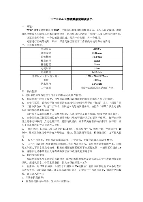
BPW250/6.3型喷雾泵使用说明书一、概述:BPW250/6.3型喷雾泵与WGZ1过滤器组组成相应的喷雾泵站,是为各种采煤机、掘进机提供喷雾灭尘所需压力水的配套设备,也可作以乳化液为介质的中压液压系统的动力源。
该泵站由两台泵、一台过滤器组组成,泵为一台使用,另一台被用。
对泵进行正确的使用、维护、保养是保证泵正常工作及提高使用寿命的关键。
四、泵的使用1、使用单位必须指定经专门培训的泵站司机操作管理。
2、泵站使用中应水平放置,以免引起箱体内润滑油面的倾斜而影响各部分的润滑。
3、在使用泵前,首先应仔细检查润滑油在油标上的油位是否在“红线”以上,“绿线”以下。
工作中油位在“红线”以下时,难以建立良好的润滑条件,油位在“绿线”以上时增加润滑油的搅拌易引起油温过高。
同时检查各部位机件有无损坏及松动,各连接管道是否有参漏,吸液管是否有曲折。
4、在全面检查后将泵吸液腔放气螺堵拧松(吸液管拆卸以后也要同样处理)。
打开自卸阀组上的手动卸载阀,点动电源开关,观察电机转向,应和旋向标牌的方向相同,如不符,应纠正电机接线后方可启动投入使用。
5、泵启动后,拧松高压腔压盖上的M16螺钉,放尽腔内空气,然后拧紧。
空载运行5~10分钟,这时泵在运动中不得有异常噪音,抖动、管路泄露等现象,检查无误后,方可投入使用。
6、投入工作初期,要经常注意箱体温度,不宜过高,工作中油温不应超过70℃。
7、工作中应注意柱塞密封和卸载阀的工作压力是否正常,如柱塞密封处漏液严重,卸载阀工作压力不正常要及时处理。
柱塞密封圈的压紧螺帽不应压得过紧,一般压紧后退出1/6圈,柱塞在运动中其表面允许有成微滴状而不成线状的泄露水珠。
五、泵的维修和保养泵站是采煤机喷雾系统的关键设备,合理的维修和保养是延长该泵的使用寿命和保证采煤机、掘进机正常工作的重要条件,因此必须做好这一工作。
1、润滑油:用N68机械油。
(相当于旧用国标50#机械油)润滑油在泵运行150小时左右应进行换油,同时清洗油池,油必须再滤网口加入,正常运行中作适当补充,加油时严防煤粉,矸石进入箱体内。


尊敬的用户:感谢您选用我公司的产品,本说明书是我公司高压电机滚动轴承装置的专用说明书,是电机使用说明书的补充,仅适用于使用滚动轴承的高压电机,如有疑问,请随时与我们联系,我们十分感谢!Dear Customers,Thanks for your correct choice of our products. This Handbook is available for the high voltage motors with rolling element bearings. It is the supplement to the motor operation instructions.Any queries, please do not hesitate to contact the manufacturer.。
目录1.滚动轴承装置的概述 (4)2.滚动轴承的工作温度……………………………………………第页3.滚动轴承的润滑方式及润滑剂 (5)4.滚动轴承的维护与保养 (7)5.轴承安装与拆检时应注意的事项 (8)6.运转检查与故障处理 (9)7.轴承滚动声的附加说明 (10)Content1. Descriptions of Rolling Element Bearing Device Page 42. Working Temperature of Rolling Element Bearing Page53. Regreasing Method and Lubrication Page 64. Maintenances Page75. Attentions for Bearing Assembly and Disassembly Page 86. Check and Failure Solutions Page 97. Additional Remarks to Bearing Sound Page 10一. 滚动轴承装置的概述我公司高压电机所选用的滚动轴承均为高品质的轴承产品.滚动轴承的机械设计寿命均经过严格的核算,满足用户的使用要求,同时核算了滚动轴承的最小负荷,保证轴承工作在最佳工作状态.轴承装置带不停机注排脂(油)结构, 可在不停机情况下加注或排出润滑脂(油).我公司常用的滚动轴承的主要类型及配置见表1:表1出,如需详细的资料,请向我们索取.1. Descriptions of Rolling Element Bearing DeviceHigh quality rolling element bearings are adopted for the high voltage motors. Bearing life and minimum load are calculated to meet the customer’s demand and ensure the best operation conditions of bearings. Such bearings are equipped the regreasing attachment to add or drain out the grease (oil) without stop.The main adopted bearing types are shown in Table.Table 1if the bearing device is other than the illustrations.二.滚动轴承的工作温度通常,轴承的温度随着运转的开始慢慢上升,1~2小时后达到稳定的工作状态.如果润滑、安装不合适,则轴承温度会急骤上升,出现异常高温,这时必须停止运转,采取必要的防范措施.滚动轴承的工作温度不得超过95℃,报警温度为90℃,停机温度为95℃. 据用户的需求, 每个轴承可设测温元件(Pt100),将其引线引入测温接线盒内,提供远传温度信号或进行温度显示.轴承测温点的位置距离轴承外圈不超过10mm.2. Working Temperature of Rolling Element BearingGenerally the bearing temperature rises gradually and shall be stabilized in 1 or 2 hours. The bearing temperature will increase rapidly if the grease (oil) or assembly does not match the bearing. If so the motor shall be stopped immediately to take necessary actions.The working temperature for rolling element bearing is 95℃. Upon request Pt100s are equipped as monitoring detectors for bearing temperature. The detectors will alarm if the bearing temperature reaches 90℃and the motor will stop if the bearing temperature reaches 95℃..The lead wires of detectors are brought out to the auxiliary terminal box for remote control or signal indication. The bearing temperature measuring points shall not exceed 10mm far away from the outer bearing race.三.滚动轴承的润滑方式及润滑剂轴承润滑的目的是要在构成轴承的滚道轮、滚动体及保持架相互接触的部分形成一层油膜,以防止各面直接接触,具有减少摩擦及磨损、延长疲劳寿命、排出摩擦热、防止异物侵入、防止生锈与腐蚀的作用.润滑的方式有两种,即脂润滑和油润滑。
.前言目录前言 . (2)一、车辆外型图 . (3)二、车辆主要技术参数 . (7)三、车辆主要结构 . (9)1.车架 92.锁栓装置93.备胎升降器 94.防护栏 95.车轴、轮胎、钢圈 96.悬架系统107.升降支腿108.牵引销 119.气路系统1110. ABS 系统 1211. 电路系统 12四、车辆使用和操作 . (13)1.牵引车与半挂车的连接 132.载货 143.行驶 144.分离 155.确保车辆在行驶中的安全而必须注意或采取的事项如下15五、车辆标识 . (16)1.铭牌 142.车辆识别代码14六、车辆日常及定期维护 . (16)七、车辆检查保养要领. (19)1.检查时注意事项192.检查全部管道193.检查紧急继动阀184.检查制动气室195.检查储气筒 196.检查管道和接头207.制动调整臂及制动器的调整 208.连接螺栓螺母的调整209.轮胎保养 2010. 悬挂装置 2011. 牵引销及牵引销板 20八、润滑 . (21)九、常见故障原因及其排除方法 . (22)十、保修卡 . (23)一、车辆外型图20英尺双轴骨架/ FJZ9280TJZG 40英尺双轴骨架 /FJZ9350TJZG40英尺双轴骨架 /FJZ9400TJZG 40英尺三轴平板 /FJZ9380TJZP双轴低平板/ FJZ9230TDP 双轴低平板/ FJZ9280TDP40英尺三轴平板/ FJZ09280TP 13米三轴栏板 /FJZ9390TLP二、车辆主要技术参数型号FJZ9280TJZG FJZ9350TJZG FJZ9400TJZG FJZ9380TJZP型式20英尺双轴骨40’骨架式40 7 骨架式40 7 平板式架式轴数2233整备质量 (kg)4150450065007350装载质量 (kg)24000305003310030480最大总质量 (kg)28150350003960037830鞍座最大允许总质量10350170201565014710(kg)长(mm)7850124001240012400外廓尺寸宽(mm)2480248024802480高(ram)1510148015101520轴距(mm)5050+13108150+13607470+1360+13607000+1310+1310轮距(mm)1840 1 84018401840前悬(mm)6006506501050后悬(mm)890224015601730前回转半径 (mm)820134013401540间隙半径 (mm)2090232023202320牵引座结合面离地高1 180122012201200度(mm)离去角 ( 。
尊敬的用户:感谢您选用我公司的产品,本说明书是我公司高压电机滚动轴承装置的专用说明书,是电机使用说明书的补充,仅适用于使用滚动轴承的高压电机,如有疑问,请随时与我们联系,我们十分感谢!Dear Customers,Thanks for your correct choice of our products. This Handbook is available for the high voltage motors with rolling element bearings. It is the supplement to the motor operation instructions.Any queries, please do not hesitate to contact the manufacturer.。
目录1.滚动轴承装置的概述 (4)2.滚动轴承的工作温度……………………………………………第页3.滚动轴承的润滑方式及润滑剂 (5)4.滚动轴承的维护与保养 (7)5.轴承安装与拆检时应注意的事项 (8)6.运转检查与故障处理 (9)7.轴承滚动声的附加说明 (10)Content1. Descriptions of Rolling Element Bearing Device Page 42. Working Temperature of Rolling Element Bearing Page53. Regreasing Method and Lubrication Page 64. Maintenances Page75. Attentions for Bearing Assembly and Disassembly Page 86. Check and Failure Solutions Page 97. Additional Remarks to Bearing Sound Page 10一. 滚动轴承装置的概述我公司高压电机所选用的滚动轴承均为高品质的轴承产品.滚动轴承的机械设计寿命均经过严格的核算,满足用户的使用要求,同时核算了滚动轴承的最小负荷,保证轴承工作在最佳工作状态.轴承装置带不停机注排脂(油)结构, 可在不停机情况下加注或排出润滑脂(油).我公司常用的滚动轴承的主要类型及配置见表1:表1出,如需详细的资料,请向我们索取.1. Descriptions of Rolling Element Bearing DeviceHigh quality rolling element bearings are adopted for the high voltage motors. Bearing life and minimum load are calculated to meet the customer’s demand and ensure the best operation conditions of bearings. Such bearings are equipped the regreasing attachment to add or drain out the grease (oil) without stop.The main adopted bearing types are shown in Table.Table 1if the bearing device is other than the illustrations.二.滚动轴承的工作温度通常,轴承的温度随着运转的开始慢慢上升,1~2小时后达到稳定的工作状态.如果润滑、安装不合适,则轴承温度会急骤上升,出现异常高温,这时必须停止运转,采取必要的防范措施.滚动轴承的工作温度不得超过95℃,报警温度为90℃,停机温度为95℃. 据用户的需求, 每个轴承可设测温元件(Pt100),将其引线引入测温接线盒内,提供远传温度信号或进行温度显示.轴承测温点的位置距离轴承外圈不超过10mm.2. Working Temperature of Rolling Element BearingGenerally the bearing temperature rises gradually and shall be stabilized in 1 or 2 hours. The bearing temperature will increase rapidly if the grease (oil) or assembly does not match the bearing. If so the motor shall be stopped immediately to take necessary actions.The working temperature for rolling element bearing is 95℃. Upon request Pt100s are equipped as monitoring detectors for bearing temperature. The detectors will alarm if the bearing temperature reaches 90℃and the motor will stop if the bearing temperature reaches 95℃..The lead wires of detectors are brought out to the auxiliary terminal box for remote control or signal indication. The bearing temperature measuring points shall not exceed 10mm far away from the outer bearing race.三.滚动轴承的润滑方式及润滑剂轴承润滑的目的是要在构成轴承的滚道轮、滚动体及保持架相互接触的部分形成一层油膜,以防止各面直接接触,具有减少摩擦及磨损、延长疲劳寿命、排出摩擦热、防止异物侵入、防止生锈与腐蚀的作用.润滑的方式有两种,即脂润滑和油润滑。
BENCH DRILL PRESSOWNER'S MANUALItem # WARNING:Read carefully and understand all INSTRUCTIONS beforeoperating. Failure to follow the safety rules and other basicsafety precautions may result in serious personal injury.45266Thank you very much for choosing a Northern Industrial Tools Product!For future reference, please complete the owner's record below:Model: _______________ Purchase Date: _______________Save the receipt, warranty and these instructions. It is important that you read the entire manual to become familiar with this product before you begin using it.This machine is designed for certain applications only. The distributor cannot be responsible for issues arising from modification. We strongly recommend this machine is not modified and/or used for any application other than that for which it was designed. If you have any questions relative to a particular application, DO NOT use the machine until you have first contacted the distributor to determine if it can or should be performed on the product.For technical questions please call 1-800-222-5381.INTENDED USEThis bench drill press is designed for drilling in metal or wooden pieces.TECHNICAL SPECIFICATIONSDescription SpecificationsMotor:1/2 HPVolts:120VSpeed:570 - 3050 RPMChuck Size:1/2”Swing:10"Stroke:21/3"Drilling Capacity:1/2”Work tabel:715/16" x 73/4"Work base:1311/16" x 81/4"Ship Weight:71 lbsGENERAL SAFETY RULESin electric shock, fire and/or serious injury.that common sense and caution are factors which cannot be built into this product, but must besupplied by the operator.SAVE THESE INSTRUCTIONSWORK AREA• Keep work area clean, free of clutter and well lit. Cluttered and dark work areas can cause accidents.• Do not use your tool where there is a risk of causing a fire or an explosion; e.g. in the presence of flammable liquids, gasses, or dust. Power tools create sparks, which may ignite the dust or fumes.• Keep children and bystanders away while operating a power tool. Distractions can cause you to lose control, so visitors should remain at a safe distance from the work area.12• Be aware of all power lines, electrical circuits, water pipes and other mechanical hazards in your work area, particularly those hazards below the work surface hidden from the operator's view that may beunintentionally contacted and may cause personal harm or property damage.• Be alert of your surroundings. Using power tools in confined work areas may put you dangerously close to cutting tools and rotating parts.ELECTRICAL SAFETYWARNING!Always check to ensure the power supply corresponds to the voltage on the rating plate.• Do not abuse the cord. Never yank tool or extension cords from the receptacle. Keep power and extension cords away from heat, oil, sharp edges or moving parts. Replace damaged cords immediately.Damaged cords may cause a fire and increase the risk of electric shock.• Grounded tools must be plugged into an outlet properly installed and grounded in accordance with all codes and ordinances. Never remove the grounding prong or modify the plug in any way. Do not use any adapter plugs. Check with a qualified electrician if you are in doubt as to whether the outlet is properly grounded. • Double insulated tools are equipped with a polarized plug (one blade is wider than the other). This plug will fit in a polarized outlet only one way. If the plug does not fit fully in the outlet, reverse the plug. If it still doesn't fit, contact a qualified electrician to install a polarized outlet. Do not change the plug in any way.• Avoid body contact with grounded surfaces such as pipes, radiators, ranges, and refrigerators. There is an increase risk of electric shock if your body is grounded.• When operating a power tool outside, use an outdoor extension cord marked “W-A” or “W.” These cords are rated for outdoor use and reduce the risk of electric shock.• Extension Cord Use:A. Use only 'Listed' extension cords. If used outdoors, they must be marked “For Outdoor Use.” Thosecords having 3-prong grounding type plugs and mating receptacles are to be used with grounded tools.B. Replace damaged or worn cords immediately.C. Check the name plate rating of your tool. Use of improper size or gauge of extension cord may causeunsafe or inefficient operation of your tool. Be sure your extension cord is rated to allow sufficient current flow to the motor. For the proper wire gauge for your tool, see chart.•Do not expose power tools to rain or wet conditions. Water entering a power tool will increase the risk of electric shock.• Do not let your fingers touch the terminals of plug when installing to or removing from the outlet.• Ground fault circuit interrupters. If work area is not equipped with a permanently installed Ground Fault Circuit Interrupter outlet (GFCI), use a plug-in GFCI between power tool or extension cord and power receptacle.PERSONAL SAFETY• Stay alert, watch what you are doing and use common sense when operating a power tool. Do not use a power tool while you are tired or under the influence of drugs, alcohol or medication. A moment of inattention while operating power tools may result in serious personal injury.• Dress properly. Do not wear loose clothing, dangling objects, or jewelry. Keep your hair, clothing and gloves away from moving parts. Loose clothes, jewelry or long hair can be caught in moving parts. Air vents often cover moving parts and should be avoided.• Use safety apparel and equipment. Use safety goggles or safety glasses with side shields which comply with current national standards, or when needed, a face shield. Use as dust mask in dusty work conditions.This applies to all persons in the work area. Also use non-skid safety shoes, hardhat, gloves, dust collection systems, and hearing protection when appropriate.• Avoid accidental starting. Do not carry the power tool with your finger on the switch. Ensure the switch is in the off position before plugging tool into power outlet. In the event of a power failure, while a tool is being used, turn the switch off to prevent surprise starting when power is restored.• Do not overreach. Keep proper footing and balance at all times.• Remove adjusting keys or wrenches before connecting to the power supply or turning on the tool. A wrench or key that is left attached to a rotating part of the tool may result in personal injury.• Never place your fingers in a position where they could contact the drill or other cutting tool if the workpiece should unexpectedly shift or your hand should slip.• Whenever possible, position the WORKPIECE to contact the left side of the column if it is too short or the table is tilted, clamp solidly to the table. Use table slots or clamping ledge around the outside edge of the table.• When using a drill press VISE, always fasten it to a table.• Never climb on or allow others to climb on the drill press table; it could break or pull the entire drill press down.• Turn the motor Switch OFF and put away the Switch Key when leaving the drill press.• To avoid injury from thrown work or tool contact, do NOT perform layout, assembly, or setup work on the table while the cutting tool is rotating.TOOL USE AND CARE• Do not force the tool. Tools do a better and safer job when used in the manner for which they are designed.Plan your work, and use the correct tool for the job.• Never use a tool with a malfunctioning switch. Any power tool that cannot be controlled with the switch is dangerous and must be repaired by an authorized service representative before using.• Disconnect power from tool and place the switch in the locked or off position before servicing, adjusting, installing accessories or attachments, or storing. Such preventive safety measures reduce the risk of starting the power tool accidentally.• Secure work with clamps or a vise instead of your hand to hold work when practical. This safety precaution allows for proper tool operation using both hands.• Store idle tools. When tools are not is use, store them in a dry, secure place out of the reach of children.Inspect tools for good working condition prior to storage and before re-use.• Use only accessories that are recommended by the manufacturer for your model. Accessories that may be suitable for one tool may create a risk of injury when used on another tool.• Keep guards in place and in working order.For your own safety, do not try to use your drill press or plug it in until it is completely assembled and installed according to the instructions, read and understood this Instruction manual:•Your drill press must be bolted securely to a workbench. In addition, if there is any tendency for your drill press to move during certain operations, bolt the workbench to the floor•This drill press is intended for use in dry conditions, indoor use only.•Always keep hands out of the path of a drill bit. Avoid awkward hand positions where a sudden slip could cause your hand to move into the drill bit.•Do not install or use any drill bit that exceeds 175 mm (7") in length or extends 150 mm (6") below the chuck jaws. They can suddenly bend outward or break.•Do not use wire wheels, router bits, shaper cutters, circle (fly) cutters, or rotary planers on this drill press. •When cutting a large piece of material make sure it is fully supported at the table height.•Do not perform any operation freehand. Always hold the workpiece firmIy against the table so it will not rock or twist. Use clamps or a vise for unstable workpieces.•Make sure there are no nails or foreign objects in the part of the workpiece to be drilled.•Do not touch the bit or chips. Drill bits and cuttings are hot immediately offer drilling.•Never reach around or under the working head, or grab the chuck key to stop the drill press.•Make sure the drill press speed is appropriate for both the type of material and bit size you are using.34• Clamp workpiece or brace against the left side of the column to prevent rotation. If it is too short or the table is tilted, clamp solidIy to the table and use the fence provided. • If the workpiece overhangs the table such that it will fall or tip if not held, clamp it to the table. Provide auxiliary support. • Make sure all clamps and locks are firmly tightened before drilling. • Securely lock the head and table support to the column, and the table to the table support before operating the drill press. • Never turn your drill press on before clearing the table of all objects. (tools, scraps of wood, etc.) • Before starting the operation, jog the motor switch to make sure the drill bit does not wobble or vibrate. • Let the spindle reach full speed before starting to drill. If your drill press makes an unfamiliar noise or if it vibrates excessively, stop immediately, turn the drill press off and unplug. Do not restart until the problem is corrected. • Do not perform layout assembly or set up work on the table while the drill press is in operation. • Make sure the spindle has come to a complete stop before touching the workpiece. • To avoid injury from accidental starting, always turn the switch "OFF" and unplug the drill press before installing or removing any accessory or attachment or making any adjustment. • Keep guards in place and in working order. • Use onIy self-ejecting type chuck key as provided with the drill press. • Do not try to drill material too small to be securely held.• Use the drill press in a well-lit area and on a level surface clean and smooth enough to reduce the risk of trips, slips, or falls. Use it where neither the operator nor a casual observer is forced to stand in line with a potential kickback.For your own safety, do not attemp to operate your drill press until it is completely assembled 1. General Safety Instructions for Power Tools 2. Getting to Know Your Drill Press 3. Basic Drill Press Operation 4. Adjustments 5. MaintenanceUNPACKINGOn receipt, carefully unpack the components ensuring that no damage was suffered in transit, and that all following parts are accounted for.A. Table Support AsmB. Column Support AsmC. ManualD. Box of Loose PartsE. BaseF. Head AsmG. Bag of Loose Parts5Check the parts againts the abovelist and refer to the diagrams.Should there be any deficiencies ordamage, you should contactthe distributor.GETTING TO KNOW YOUR DRILL PRESSASSEMBLY1.Position base on workbench.2.Remove protective sleeve from column tube and discard. Placecolumn assembly on base, and align holes in column support withholes in base.3.Locate four (4) 5/16” Dia. x 3/4” long bolts among loose parts bag.4.Install a bolt in each hole through column support and base andtighten with adjustable wrench.5.Loosen set screw in cloumn collar with 3mm HEX “L” wrench andremove collar and rack from column.1. Belt Tension Lock Handles2. Feed Handle3. Table Crank4. Chuck Key5. Chuck6. Depth Scale7. Drill “ON-OFF” Switch8. Depth Scale Lock9. Spring Cap10. Head Locks11. Bevel Scale12. Support Lock Handle13. Table Bevel Lock66.Find elevation worm gear shaft in the loose parts bag. Insert the elevation shaft into the table support and extend the shaft through the opening as far as possible. The crank is to be installed on the elevation worm gear shaft, the set screw is to be aligned with the flat portion of the shaft. The crank is to be positioned as close to the arm support as possible, then tighten set screw. (see illustration)7.With long smooth end of rack pointing upward, slide rack down through large round opening in table support. Engage rack in gear mechanism found inside opening of table support.8.While holding rack and table support in an engaged position slide both down over column. Slide rack down column until rack is positioned against lower column support.9.Replace column collar and position it bevel side down over rack. Tighten set screw in collar with 7/64” HEX “L” wrench. To let the rack slide when the table is swing to the left or right around the column, the collar must sit loosely over rack and should not be angled on the column. Only tighten set screw enough to keep collar in place, otherwise the collar may break due to excess pressure.10.Check column collar for proper adjustment. Collar should not be angled on the column and it should be positioned so rack will slide freely in collars when table is rotated 360º around column tube. If re-adjusted, only tighten set screw enough to keep collar in place.Note:To avoid column or collar damage, do not over-tighten set screw.11.Locate support lock handle in loose parts bag and tighten by hand.12.To minimize crank backlash; tighten the support lock and rotate elevation worm shaft clockwise with the crank. Loosen the set screw in the crank and reposition the crank as close to the table support as possible. Tighten the set screw in the crank.ing a 4mm HEX “L” wrench tighten the head lock set screws on the rightside of the head.OPERATIONDrill “ON-OFF” switchThis feature is intended to help prevent unauthorized and possible hazardous use by children and others.Insert KEY into switch.Note: Key is made of yellow plastic.To turn drill ON:Insert finger under switch lever and pull.To turn drill OFF:Push lever in.In an emergency: If the drill bit BINDS... STALLS...STOPS... or tends to tear the workpiece loose... you can quickly turn the drill OFF by hitting the switch with the palm of your hand.WARNING! For your own safety, always push the switch “OFF” when drill press is not in use; Remove key and keep it in a safe place. In the event of a power fallure (all of your lights go out) or blown fuse or tripped circult breaker, turn switch off, lock it and remove the key. This will prevent the drill press from starting up again when the power comes back on.MAINTENANCEWARNING! For your own safety, turn switch “off” and remove plug from power source outlet beforemaintaining or lubricating your drill press.WARNING! To avoid shock or fire hazard, if the power cord is worn or cut, or damaged in any way, have it replaced.WARNING! Make sure this tool is disconnected from its power source before attempting any maintenance, cleaning, or inspection.• Maintain your tools.It is recommended that the general condition of any tool be examined before it is used.Keep your tools in good repair by adopting a program of conscientious repair and maintenance in accordance with the recommended procedures found in this manual. If any abnormal vibrations or noise occurs, turn the tool off immediately and have the problem corrected before further use. Have necessary repairs made by qualified service personnel.• Keep cutting tools sharp and clean.Properly maintained cutting tools with sharp cutting edges are less likely to bind and are easier to control. Keep handles dry, clean, and free from oil and grease.• e only soap and a damp cloth to clean your tools. Many household cleaners are harmful to plastics and other insulation. Never let liquid get inside a tool.78WARRANTYOne-Year Limited WarrantyFor warranty questions, call 1-800-222-5381DIAGRAM & PARTS LIST9Distributed byNorthern Tool + Equipment Co., Inc.Burnsville, MN 55306Made in China。