AUMA电动执行器工程师手册
- 格式:pdf
- 大小:3.64 MB
- 文档页数:25

Technical InstructionsDocument No. A6V12035775July 7, 2020A-Series IndustrialElectric Actuators AUMA (21,300 and 40,680 lb-in)Siemens Industry, Inc.DescriptionA-Series Industrial Electric AUMA actuators provide precise, durable control of quarter turn Siemens resilient seat butterfly valves. The compact industrial housing is rated to NEMA 6P (IP 68) standards for outdoor use. All models include integrated controls and a manual override handwheel.The standard AUMA models are 120V single phase. All AUMA actuators include six auxiliary switches, torque switches, a position indicator and a heater. Modulating units provide position feedback as standard. Features• Compact, lightweight design and direct mounting • Manual, declutchable override handwheel • Position and motion indicator lights • Push button controls • CE Certified• On/off or modulating control• Output torque 21,300 lb-in (2,407 Nm) to 40,680 lb-in (4,596 Nm) • ISO 5210 for direct mounting• All actuators include a heater to prevent condensation build-up •All modulating units include a feedback potentiometerOrderingActuators can be ordered separately or together with a valve as an assembly.Product NumbersTable 1. A-Series AUMA Industrial Electric Actuators, 120V.Product Number Operating Mode Voltage 50/60 HzTorque 90° Stroke Time*Current Draw (Amps) (lb-in) (Nm) Full Load LockedRotorA226.21K On/Off120 Vac21,300 2,407 60 sec.6.514A226.41K 40,680 4,596 A266.21K Modulating21,300 2,407 A266.41K40,6804,596* Operating times shown are with 60 Hz power supply. Actuators with 50 Hz power supply will be 20% slowerWarning/Caution Notations WARNING: Personal injury or loss of life may occur if you do not perform a procedure as specified.CAUTION:Equipment damage may occur if you do not perform a procedure as specified.Technical Instructions A-Series Industrial Electric Actuators AUMA Document Number A6V12035775June 15, 2020CAUTION:Do not install or use the A-Series Industrial Electric Actuator in or near environmentswhere corrosive substances or vapors could be present. Exposure of the electricactuator to corrosive environments may damage the internal components of thedevice and will void the warranty.Application These actuators are ideal for use on valves for chillers, cooling towers, boilers, heatexchangers and other outdoor applications. The actuators’ advanced electronicsassure reliable compatibility with virtually any analog control signal used in today’sbuilding automation and temperature control systems. The NEMA 6P rated housingprevents any water ingress in outdoor applications. The built-in heater prevents anycondensation build-up inside the housing.NOTE: Use a “liquid tight” conduit connector to maintain NEMA 6P rating. SpecificationsOperating Conditions Ambient Temperature -22°F to 158°F (-30°C to 70°C)Fail Position Loss of supply power - fail-in-placeDuty Cycle On/Off – 15 min. continuous, max. six starts/minuteModulating – 25% intermittent duty Physical Description Motor 120 Vac, Single-Phase, Reversible, PermanentSplit Capacitor Induction MotorMotor Protection 1 Ph-1 thermal switch 284°F (140°C)Class F insulation, tropicalized windingControl Voltage A226.21K and A226.41K: 120 VacA266.21K and A266.41K:Input 4 to 20 mAModular Power Supply 24 VdcOutput Aux. Voltage A226.21K and A226.41K: 115 Vac – 30 mAA266.21K and A266.41K: 24 Vdc – 100 mAFeedback Signal 4 to 20 mAOutput Contacts 6 Output contacts: 6 NO/NC without common 5AOutput Signals Default setting: Fault, End pos. CLOSEDEnd pos. OPEN, Selector sw. REMOTE, Torquefault CLOSE, Torque fault OPENTerminal StripPower Terminals 8 to 10 AWG (6 to 10 mm2)Controls Contacts 14 AWG (2.5 mm2)Heater 24V Internal Supply (5 Watt)Dimensions See Figure 3 and Figure 4.Weight A2x6.21K – 165 lbs. (75 kg)A2x6.41K – 195 lbs. (88 kg)Enclosure NEMA types 6P (IP68)Corrosion Protection: KSConduit entries Plug/socket 100 mm, 2 × 3/4” NPT; 1 × 1-1/4” NPTManual operation To close the valve, turn handwheel clockwise.Drive shaft (valve) turns clockwise in closedirection. 52:1 drive ratioAngle of Rotation 92° maximumCertifications CE CertifiedCSA - Classes C322102 and C3221812(available upon request)A-Series Industrial Electric Actuators AUMA Technical InstructionsDocument Number A6V12035775July 7, 2020Product NumbersTable 2. Product Numbers.Use the product numbers in the following table to order a valve or a valve and actuator assembly. The valve product number consists of the type, action, valve size, disc type, and valve configuration.To order an assembly, add a (-) after the valve product number and then choose the application, actuator, voltage, control signal, end switches followed by a separator (.) and the actuator torque.Siemens Industry, Inc. Page 3Technical InstructionsA-Series Industrial Electric Actuators AUMADocument Number A6V12035775 July 7, 2020Page 4Siemens Industry, Inc.Mounting and InstallationAll A-Series industrial electric actuators are suitable for direct mounting on Siemens resilient seat butterfly valves.NOTE:The standard mounting position for the actuator is to orient the base of the actuator parallel to the pipeline. •To mount an actuator on a vertical pipe, position the unit with the conduit entries on the bottom to prevent condensation from entering the actuator through its conduits.• Use a “liquid tight” conduit connector to maintain NEMA 6P rating.Service The resilient seat butterfly valve and actuator are maintenance-free.WiringCAUTION: •When wiring an A-Series Industrial Electric Actuator for two-position(on/off) control and the power to the actuator is commanded to be off, you must ensure that there is no extraneous or leakage voltage between hot and common. Leakage voltage greater than 3 Vac can cause actuator failure.• When wiring an A-Series Industrial Electric Actuator for two-positioncontrol, the controller should use at minimum a one-second time delay for command signal reversal. Instantaneous command reversals may cause actuator failure.Figure 1.. On/Off .NOTE:Use this A-Series Industrial Electric Actuator only to control equipment under normal operating conditions. Where failure or malfunction of the electric actuator could lead to personal injury or property damage to the controlled equipment or other property, additional precautions must be designed into the control system. Incorporate and maintain other devices such as supervisory or alarm systems or safety or limit controls intended to warn of, or protect against, failure or malfunction of the electric actuator.Figure 2. Modulating.A-Series Industrial Electric Actuators AUMA Technical InstructionsDocument Number A6V12035775July 7, 2020 Information in this publication is based on current specifications. The company reserves the right to make changes in specifications and models as design improvements are introduced. Products or company names mentioned herein may be the trademarks of their respective owners. © 2020 Siemens Industry, Inc.Siemens Industry, Inc. Smart Infrastructure1000 Deerfield Parkway Buffalo Grove, IL 60089 USA + 1 847-215-1000Your feedback is important to us. If you havecomments about this document, please send themto***************************************Document No. A6V12035775Printed in the USAPage5of 5DimensionsFigure 3. Model A2x6.21K Actuators.Figure 4. Model A2x6.41K Actuators.。
Certificate Registration No.12 100 4269多回转电动执行器SA 07.1 - SA 16.1 SAR 07.1 - SAR 16.1AUMA MATIC操作手册2多回转电动执行器 SA 07.1 - SA 16.1 / SAR 07.1 - SAR 16.1AUMA MATIC 操作手册本手册适用于 : 本手册适用于SA(R) 07.1 - SA(R) 16.1带一体化控制单元 AUMA MATIC 多回转电动执行器本手册仅适用于“ 顺时针关”的原则,既驱动轴顺时针旋转阀门为关闭。
‘目录 页码1. 安全操作说明 . . . . . . . . . . . . . . . . . . . . . . . . . . . . . . . . . . . . . . . . . . . . . . . . 41.1 应用范围 . . . . . . . . . . . . . . . . . . . . . . . . . . . . . . . . . . . . . . . . . . . . . . . . . 41.2 简单描述. . . . . . . . . . . . . . . . . . . . . . . . . . . . . . . . . . . . . . . . . . . . . . . . . 41.3 现场接线 . . . . . . . . . . . . . . . . . . . . . . . . . . . . . . . . . . . . . . . . . . . . . . . . . 41.4 维修 . . . . . . . . . . . . . . . . . . . . . . . . . . . . . . . . . . . . . . . . . . . . . . . . . . . 41.5 注意事项 . . . . . . . . . . . . . . . . . . . . . . . . . . . . . . . . . . . . . . . . . . . . . . . . 41.6 特别说明 . . . . . . . . . . . . . . . . . . . . . . . . . . . . . . . . . . . . . . . . . . . . . . . . . 42. 技术数据 . . . . . . . . . . . . . . . . . . . . . . . . . . . . . . . . . . . . . . . . . . . . . . . . . . 52.1 多回转电动执行器SA(R) 07.1 - SA(R) 16.1 . . . . . . . . . . . . . . . . . . . . . . . . . . . . . . . 52.2 控制单元AUMA MATIC . . . . . . . . . . . . . . . . . . . . . . . . . . . . . . . . . . . . . . . . . . 53. 接线端子说明 . . . . . . . . . . . . . . . . . . . . . . . . . . . . . . . . . . . . . . . . . . . . . . .64. 存储和运输 . . . . . . . . . . . . . . . . . . . . . . . . . . . . . . . . . . . . . . . . . . . . . . . . . 75. 与阀门/齿轮箱的连接 . . . . . . . . . . . . . . . . . . . . . . . . . . . . . . . . . . . . . . . . . . . 76. 手动操作 . . . . . . . . . . . . . . . . . . . . . . . . . . . . . . . . . . . . . . . . . . . . . . . . . . 97. 电气连接 . . . . . . . . . . . . . . . . . . . . . . . . . . . . . . . . . . . . . . . . . . . . . . . . . . 107.1 接线图 . . . . . . . . . . . . . . . . . . . . . . . . . . . . . . . . . . . . . . . . . . . . . . . . . . 107.2 停机方式 . . . . . . . . . . . . . . . . . . . . . . . . . . . . . . . . . . . . . . . . . . . . . . . . . .108. 限位开关设定 . . . . . . . . . . . . . . . . . . . . . . . . . . . . . . . . . . . . . . . . . . . . . . . 118.1 关方向端限位设定(黑区) . . . . . . . . . . . . . . . . . . . . . . . . . . . . . . . . . . . . . . . . . . 118.2 开方向端限位设定(白区). . . . . . . . . . . . . . . . . . . . . . . . . . . . . . . . . . . . . . . . . 129. DUO 位置开关设定 (选项). . . . . . . . . . . . . . . . . . . . . . . . . . . . . . . . . . . . . . . . . . 129.1 关方向设定 (黑区) . . . . . . . . . . . . . . . . . . . . . . . . . . . . . . . . . . . . . . . . . . . . . 129.2 开方向设定(白区) . . . . . . . . . . . . . . . . . . . . . . . . . . . . . . . . . . . . . . . . . . . . . . 1210. 力矩开关设定 . . . . . . . . . . . . . . . . . . . . . . . . . . . . . . . . . . . . . . . . . . . . . . . 1311. 试运行 . . . . . . . . . . . . . . . . . . . . . . . . . . . . . . . . . . . . . . . . . . . . . . . . . . . 1412. 机械位置指示设定 (选项) . . . . . . . . . . . . . . . . . . . . . . . . . . . . . . . . . . . . . . . . . 1413. 电位计设定 (选项) . . . . . . . . . . . . . . . . . . . . . . . . . . . . . . . . . . . . . . . . . . . . . 1514. 电气位置反馈RWG 设定(选项). . . . . . . . . . . . . . . . . . . . . . . . . . . . . . . . . . . . . . . 1614.1 两线制4 - 20 mA 和 三/四线制0 - 20 mA 设定.. . . . . . . . . . . . . . . . . . . . . . . . . . . . . . 1714.2 三/四线制 4 - 20 mA 设定 . . . . . . . . . . . . . . . . . . . . . . . . . . . . . . . . . . . . . . . . 1815. AUMA MATIC 编程 . . . . . . . . . . . . . . . . . . . . . . . . . . . . . . . . . . . . . . . . . . . . .1915.1 接口板上 LEDS 功能(标准配置) . . . . . . . . . . . . . . . . . . . . . . . . . . . . . . . . . . . . . . 1915.2 逻辑板编程 . . . . . . . . . . . . . . . . . . . . . . . . . . . . . . . . . . . . . . . . . . . . . . . . 2015.3 紧急关和紧急开信号 (选项) . . . . . . . . . . . . . . . . . . . . . . . . . . . . . . . . . . . . . . . . 213多回转电动执行器 SA 07.1 - SA 16.1 / SAR 07.1 - SAR 16.1操作手册AUMA MATIC. . . . . . . . . . . . . . . . . . . . . . . . . . . . . . . . . . . . . . . . . . . . . . . . . . . . . . 页码16. 定位板(选项) . . . . . . . . . . . . . . . . . . . . . . . . . . . . . . . . . . . . . . . . . . . . . . . . 2116.1 技术参数 . . . . . . . . . . . . . . . . . . . . . . . . . . . . . . . . . . . . . . . . . . . . . . . . . 2116.2 设定 . . . . . . . . . . . . . . . . . . . . . . . . . . . . . . . . . . . . . . . . . . . . . . . . . . . 2116.3 关方向终端位置调整(标准配置) . . . . . . . . . . . . . . . . . . . . . . . . . . . . . . . . . . . . . 2316.4 开方向终端位置调整(标准配置 . . . . . . . . . . . . . . . . . . . . . . . . . . . . . . . . . . . . 2416.5 灵敏度调整 . . . . . . . . . . . . . . . . . . . . . . . . . . . . . . . . . . . . . . . . . . . . . . . 2516.6 开方向终端位置调整(标准配置)(反向操作) . . . . . . . . . . . . . . . . . . . . . . . . . . . . . 2516.7 关方向终端位置调整(标准配置)(反向操作). . . . . . . . . . . . . . . . . . . . . . . . . . . . . . 2616.8 分段位置设定功能(选项) . . . . . . . . . . . . . . . . . . . . . . . . . . . . . . . . . . . . . . . . . 2716.8.1 分段功能描述 . . . . . . . . . . . . . . . . . . . . . . . . . . . . . . . . . . . . . . . . . . . . . . 2716.8.2 编程 . . . . . . . . . . . . . . . . . . . . . . . . . . . . . . . . . . . . . . . . . . . . . . . . . . 2716.8.3 分段位置设定 . . . . . . . . . . . . . . . . . . . . . . . . . . . . . . . . . . . . . . . . . . . . . 2717. 定时功能 (选项) . . . . . . . . . . . . . . . . . . . . . . . . . . . . . . . . . . . . . . . . . . . . . . 2817.1 LEDs (定时)自诊断功能 . . . . . . . . . . . . . . . . . . . . . . . . . . . . . . . . . . . . . . . . . 2817.2 定时器设定 . . . . . . . . . . . . . . . . . . . . . . . . . . . . . . . . . . . . . . . . . . . . . . . 2918. 保险装置 . . . . . . . . . . . . . . . . . . . . . . . . . . . . . . . . . . . . . . . . . . . . . . . . . 3019. 维修 . . . . . . . . . . . . . . . . . . . . . . . . . . . . . . . . . . . . . . . . . . . . . . . . . . . 3020. 一体化控制单元 AUMA MATIC 测试 . . . . . . . . . . . . . . . . . . . . . . . . . . . . . . . . . . . 3121. 遵从标准声明 . . . . . . . . . . . . . . . . . . . . . . . . . . . . . . . . . . . . . . . . . . . . . . 33索引 . . . . . . . . . . . . . . . . . . . . . . . . . . . . . . . . . . . . . . . . . . . . . . . . . . . 34AUMA办公室和代表处的地址 . . . . . . . . . . . . . . . . . . . . . . . . . . . . . . . . . . . . . 351. 安全操作说明1.1 应用范围 AUMA 电动执行器用于操作球阀,蝶阀,闸阀等工业阀门。
aumasa07说明书
一、使用前先将气动阀门内杂物和铁屑用清水进行清洗。
二、气动阀门在关闭状态下,阀内还会有些残留介质,要切断电源和气源再进行清理,把阀体内压力要完全释放出来。
三、阀门一般都会使用密封材料防泄露和磨损,需要定期对密封材料进去清理。
四、法兰上螺母和螺栓要固定紧,以防法兰面之间受理不匀导致垫面损坏或破裂,导致阀门法兰对接出介质泄露。
五、如果阀门长期是露天工作的会导致阀门和部件生锈可能会使阀门无法正常使用,所以需要保养和测试,以保性能的稳定运行气动阀门使用固定半年或是一年需要定期加执行器使用轮滑油,从而起到对执行器更好的保养与其延长执行器的使用寿命。
AUMA电动执行器操作说明
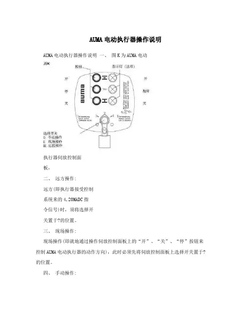
AUMA电动执行器操作说明一、图K为AUMA电动
执行器伺放控制面
板,
二、远方操作:
远方(即执行器接受控制
系统来的4,20MADC指
令信号)时,须将选择开
关置于?的位置。
三、现场操作:
现场操作(即就地通过操作伺放控制面板上的“开”、“关”、“停”按钮来控制AUMA电动执行器的动作方向),此时必须先将伺放控制面板上选择开关置于?的位置。
四、手动操作:
当AUMA电动执行器出现电路故障时,如需操作可通过就地旋转手轮来控制AUMA电动执行器的动作方向,具体操作方法如下: 1、先将伺放控制面板上选择开关置于0的位
置。
2、抬起手轮中间的切换手柄到85度,慢慢摇
动手轮直到手动操作(图D)。
注意,切换手柄足以满足手动切换的操作,任
何附加办法都不需要也不允许,过力的操作会损坏切换装置。
3、放下切换手柄到原始位置,如果没有回到原
位,用手放回(图E)。
4、根据需要方向旋转手轮 (图 F)。
5、手动操作有效直到再次电动(送电时自动恢
复电动),当马达启动时,手动操作会自动
脱开。
手动操作注意事项:因AUMA电动执行器具有机械过力矩保护功能,手动操作时如感觉手轮摇动“较沉”,此时严禁继续操作,应及时联系热工检修人员处理,避免损坏执行机构。
操作说明手册的封面内容翻译(中英文对照):Multi-turn actuators万向驱动装置(产品型号)SAR (产品型号)AUMA NORM (AUMA是这个阀门生产厂的品牌名称)AUMA标准Operation instructions (操作手册)目录内容:Scope of these instructions:本手册内容介绍的范围包括:These instructions are valid for multi-turn actuators for Open-close duty, SA ,and multi-turn actuators for modulating duty, .本手册的说明适应型号为SA 、具有开启-关闭功能系列的万向驱动装置和型号为、具有调节功能系列的万向驱动装置有效。
These operations instructions are only valid for “clockwise closing”, . driven shaftturns clockwise to close the valve.这些操作说明只对"顺时针关闭"有效,即:驱动轴顺时针转动关闭阀门。
.Safety instructions (安全说明 )Range of application (应用的范围 ) AUMQ multi-turn actuators are designed for the operation of industrial valves, , globe valves, butterfly valves and ball valves. For other applications, please consult us. AUMA is not liable for any applications. Such risk lies entirely with the user. AUMQ万向驱动装置是为工业用阀所设计的,例如:工业生产常用球瓣阀,蝶阀和球阀。
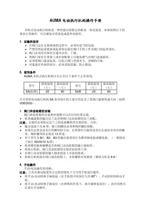
AUMA电动执行机构操作手册多转式电动执行机构是一种性能比较稳定的机电一体化装置。
如果按照以下的要求正常操作,可以避免对设备造成意外的损坏。
1.运输和保存¾在阀门运往安装现场的过程中,必须有适当的包装。
¾严禁用将起重链条或起重钩安装在阀门手轮上作为阀门的起重部位。
¾阀门必须室内保存且通风良好,干燥。
¾将阀门保存在货架上或木制框架上以避免潮气对阀门造成损坏。
¾必须将阀门遮盖起来,以防止阀门受到灰尘、杂物的污染。
¾对暴露在外面的部分,必须采取措施,防止腐蚀。
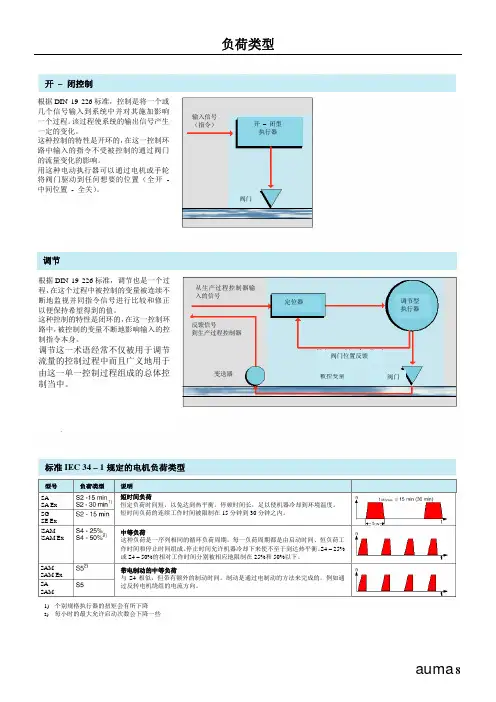
2.使用条件AUMA多转式执行机构可以正在以下条件下正常使用:型号最低温度(℃)最高温度(℃)型号最低温度(℃)最高温度(℃)SA(标准) -25 80 SAR -25 60开关型的电动执行机构SA系列设计的主要目的是为了使阀门能够快速关闭(按照VDE0530)。
3. 阀门和齿轮箱的安装阀门和齿轮箱的安装和控制箱可以在任何位置安装。
¾检查减速箱的输出法兰是否和阀门及齿轮箱的法兰相配。
注意:安装时必须保证法兰上的连接螺栓的安装轻松、自如。
¾输出连接口为A型:插口的螺纹必须和阀杆螺纹相配。
¾如果在定货是没有注明螺母的方向,在供货时只提供没有打孔或没有攻丝的螺母。
阀杆螺母的安装见13所述。
¾对于型号为B1,B2,B3的输出装置设计为锥形轴连接或键连接。
(一般情况下执行ISO5210 标准)。
¾检查锥形轴和键槽是否和阀门及齿轮箱的输入轴相符。
¾将执行机构、阀门及齿轮箱的安装表面清理干净。
¾在阀门及齿轮箱的输入轴表面涂上少量润滑油。
¾将执行机构放在阀门或齿轮箱上,并将螺栓对角紧固(紧固力矩见8.8)4.手动操作手动-电动操作的切换:注意:只有在驱动装置停止运转的情况下方可用手轮进行操作。
¾将手动-电动转换手柄抬起(在手轮的中间部位大约850),手动轻轻的转动手轮。
AUMA多回转电动执行器使用说明AUMA多回转电动执行器是一种电动执行器,适用于需要多个回转的应用场景。
它具有可靠的性能,广泛应用于工业自动化系统中。
本文将详细介绍AUMA多回转电动执行器的使用说明,包括安装、操作、维护等方面的内容。
一、安装1.在安装AUMA多回转电动执行器之前,需要确保执行器的型号、规格与系统要求相符,同时检查执行器是否有损坏或异常。
2.在安装前应先检查电动执行器的工作环境是否满足要求,确保没有过于恶劣的温度、湿度、腐蚀等条件。
3.安装执行器时,应确保其与阀门或执行器连接部位的尺寸、标高以及安装方式等参数符合要求,并正确选择连接方式(螺纹连接、法兰连接等)。
4.为了保证执行器的正常工作,还需确保电源电压、控制信号的准确、稳定,同时还应根据执行器的特性配置适当的防雷设备。
二、操作1.在开始操作前,首先需要确保执行器的电源已经接通,并检查控制信号是否正常。
2.执行器控制方式可以选择手动方式或自动方式。
当选择手动方式时,可使用手轮或手柄直接控制执行器的运动。
当选择自动方式时,可通过PLC或DCS等系统发送控制信号,实现对执行器的远程控制。
3.在执行器使用过程中,应根据需要合理设置控制信号,控制执行器的开度,以达到所需的工作效果。
4.当执行器出现异常情况(如电源故障、阀门运行异常等)时,应立即停止使用,并采取必要的维修措施。
三、维护1.定期检查执行器的工作状态,包括电源供应、控制信号等。
如发现异常情况,应及时排除。
2.对于执行器的密封件、传动机构、电机等关键部件,应定期进行润滑和保养。
3.执行器的运动部分应保持清洁,并使用适当的防尘、防水措施,以延长其使用寿命。
4.若执行器需要更换密封件、传动件等零部件时,应选择与原装件相同的型号和规格,并确保更换工作在停电、停水的情况下进行。
5.对于长时间不使用的执行器,应注意对其进行防腐蚀处理,同时定期进行试运行,以确保其正常工作。
以上就是AUMA多回转电动执行器的使用说明。
auma matic的结构及其功能说明带auma matic的电动执行器由如下部分组成:执行器基本出力部分auma norm 安装在执行器基本部分上的可编程点机一体化控制单元auma matic 将电机一体化控制单元与电动执行器组合到一起有以下几种优点:与普通的不带控制单元的执行器的布线相比由于大大简化了现场的布线工作量,因此可以节约大量的费用。
由于继电器不是安装在遥远的电气控制柜中,因此在扭矩开关或行程开关被侵压以后电机会立刻停止转动不会产生过长的延时。
可以被轻易而灵活地组合到各种各样的过程控制系统中或者组合到一个标准化的现场总线系统中,例如:profibus-fms,profibus-dp,interbus-s或modbus-rtu。
电机一体化控制单元auma matic由以下几个模块组成:用于控制电机电源的换向接触器。
操作和信号电路板-带有初级熔断器,和用于将现场按扭发出的控制命令传递到电子电路的继电器;应客户的要求还可带上做为任选件的指示灯。
接口板-带有用于隔离内部信号和外部信号之间电位差的光电隔离器,继电器和发光二极管指示灯。
以smd技术设计的路基板-其上装有c-mos场效应管。
它提供了对内部信号和开关信号之间的连接进行编程以及用dip开关设定电机控制的可能性。
连接执行其本身auma norm和电机一体化控制单元auma matic的auma插拔式电气连接器。
为用户接线而提供的auma插拔电气连接器。
带有现场/远程选择器电机控制单元供电用的电源供应单元。
电机一体化控制单元auma matio的模块化设计结构使得对其配置的修改变得非常容易。
在不带一体化控制单元得执行器(auma norm)上的auma插拔式电器连接器与电机一体化控制单元(auma matic)上的电气连接器是完全相同的。
这使得auma电动执行器得升级改型非常容易。
电动机得一体化控制单元auma matic可以被安装在以下型号规格得执行器上:多回转执行器: sa07.1-sa16.1(用于开-闭控制)sam07.1-san16.1(用于调节控制)部分回转执行器:sg05.1-sg12.1 最新开发得纺爆型auma matic可以直接安装到auma norm防爆型执行器sa ex,sam ex或sg ex上,使其改型升级为带电动机一体化控制单元的防爆型电动执行器。
索引auma 31A ccessories AUMA MATIC 19, 20AC-motor 13Actual value 23, 26 Actuator types 11Actuator versions 7, 8, 11 After sales service 25Ambient temperature 11, 30 Applications 4AUMA MA TIC 8, 10, 18, 19, 20, 24AUMA NORM 8, 10 AUMA plug/socket connector 21, 25, 27 AUMA SEMIPACT 23 B evel gearbox 6, 7Blinker switch 15, 22, 25 BUS-system 28 C able glands 27Certificate of conformity 11 Colour 10Command signal (see reference input signal) 9, 19, 20, 22 Conduit entries 24 Controls 9, 10, 20Controlled variable 9, 19 Control unit 9, 21Corrosion protection 10, 14 D C-motor 13Declaration of conformity 11 Definition multi-turn actuator 3 Definition part-turn actuator 3 Delay time 20, 21, 24 DesignAUMA NORM 9pp. 21, 24, 26, 27 DesignAUMA MATIC 9, 11, 14, 16, 20pp, 26ppDUO-limit switching 16, 22 E lectrical connections 27Electronic position transmitter 26 EMC-Directve 11 EU-Directives 11 Enclosures 10Explosion protection 10, 24 External controls 9 F eedback 8, 23, 26 Fieldbus 28Fieldbus board 23 G earing 6, 7, 12 I mpulse time 17Inductive position transmitter 22 Indication lights 21, 23, 24, 25 Input signal 8, 19, 20, 22 Insulation class 13Integral controls 8, 10, 18 INTERBUS-S 28 Interface board 21ppIntermediate switches (see DUO-limit switches) 16, 22 Intermittent duty 8, 17 ISO 9001 30L imit switching 15Linear thrust unit 6, 7, 12Local control station 9, 21, 23 Logic board 21, 22Low voltage Directive 11 M anual operation 12 Mechanical position indicator 16Microswitch: refer to single or tandem switch 14, 15 Modulating duty 8, 17, 23 Modulating torque 17 Monitoring 24 Motors 13Motor controls 9, 21pp Motor operation 12Motor protection 13, 14, 25 Motor switch gear 20 Mounting position 11Multi-turn actuator 3, 5, 12 N oise level 11Number of starts 17, 23 Nominal value 8, 22, 23, 26 O pen-close duty 8, 17 One-phase AC motor 13 Operating movement 6 Operating time 29 Optional devices 16 Order forms 30Output speeds 16, 29 Output drive forms 12 Output signals 26 P arking socket 27 Part-turn actuator 6, 7 PLC (programmable logic controller) 23Plug/socket connector 21, 25, 27 Positioner 23, 26 Position indication 16 Position transmitter 26 Potentiometer 22, 26Power supply unit 21, 25, 26 Power supply board 24, 27 Product quality 30 PROFIBUS-FMS 28Programming AUMA MATIC 22 Programmable logic device (PLC) 28Proposed wiring diagram AUMA NORM 20 Protective earth 24 Protection cover 27 Push buttons 21, 25 Q uality assurance 30 R eduction gearing 16, 26 Reference input signal 8, 23 Regulating duty (seemodulating duty) 8, 17, 23 Remote control centre 9, 25 Remote controls 24Remote indication 24Reversing contactors 21pp S chematic wiring AUMA MATIC 25 Selection criteria 6, 7Selector switch 21, 22, 24, 25 Self-locking 16Service conditions 10, 11 Service factors 30 Service life 29Short-time duty 8, 17 Signals 26Single switch 15Single-phase AC motor 13 Sizing data 29Sizes of actuators 17 Space heater 16, 20, 25 Specifications, samples 30 Speeds 16Spur gearbox 6, 7 Switches 15, 16 Switch rating 15, 16 T andem switches 15 Technical data 17, 24 Technical features 13, 14 Temperature range 11 Terminal plans 20 Terminals 27 Thermistor 14Thermoswitch 14, 25Three-phase AC motor 13 Thyristor unit 23 Timer board 20Torque determination 30 Torques 17, 30Torque switching 15 Travel / Stroke 26 Tripping torque 15, 17 Two-wire system 28 Types of duty 8 U ndervoltage 30 V alve types 6, 29V alve attachment 12, 17 V alve position 26 V alve travel 26V elocity of valve stem 16 V ersions 9, 10, 11 V oltages 13, 29 W all bracket 23 Warranty 30Winding temperature 14Wiring diagram AUMA MA TIC 21 Wiring proposals AUMA NORM 20 Worm gearbox 12欧玛电动执行器有限公司北京代表处北京市朝阳区马甸裕民路12号元辰鑫大厦E1座602室邮编:100029电话:+86-10-62022491/92/93/94/95传真:+86-10-62022496/97电子邮箱:aumabs@, aumabs@。
信号阀门开度的大小可以被当做以下用途的信号传输出来:●用于远程指示的连续信号●传输给定位板的反馈信号要连续将阀门开度信号传输出来那么就必须在执行器的开关控制舱中安装一个齿轮减速机构。
位置反馈装置提供一个模拟量参照信号。
高精度电位计●线性精度 1%;0.5 W●标准电阻值:0.2 K ,适用于AUMA供电单元PS 01和指示仪表(请参照独立的参数表)●任选阻值:0.1 K ,0.5 K ,1.0 K 或5.0 K双联式高精度电位计●线性精度 1%;0.5 W●标准阻值:0.2 / 0.2 K●任选阻值:0.5 / 0.5 K ,1.0 / 1.0 K ,5.0 / 5.0 K 或0.2 / 5.0 K注:因为只能提供固定的几种减速比的减速齿轮机构,并不是在所有的情况下都能找到合适减速比的减速齿轮机构,所以在有些情况下电位计并不能被在从0到最大值的整个范围内使用。
为了能在包括上述这种情况下都能使用,就必须配备一个外部微调电位计。
用来给AUMA NORM供电的供电装置对于位置变送器的电源供应,我们推荐采用AUMA电源供应单元PS 01。
要了解更详细的情况请参阅独立的参数表。
电子位置变送器RWG由电位计首先将电动执行器的输出动作转换成电压信号。
再经过电子变送器将该电压信号转换成电流信号。
通过电子板上的微调电位计可以很容易地调整反馈信号的零点和跨度。
输出信号2线制3或4线制电源电压环境温度机械寿命4 - 20 mA0 / 4 - 20 mA24 V DC15%经滤波处理- 40 ℃到+ 70 ℃至少5×10⁸次循环要了解更详尽的情况,请参阅样本「电子位置变送器」。
我们也可以根据要求提供感应式电子位置变送器(LVDT,相对运动部件无接触)。
输入信号电动机一体化控制单元AUMA MA TIC接受以下信号:●从RCC(远程控制中心)发来的开启、停止、关闭或开启、关闭等控制指令。
●模拟量控制信号:0 - 20 mA,4 - 20 mA,或0 -5 V信号,做为一体化定位板(任选件)的比较参考输入信号。
操作说明手册的封面内容翻译(中英文对照):Multi-turnactuators万向驱动装置SA07.1-SA48.1(产品型号)SAR07.1-SAR30.1(产品型号)AUMANORM(AUMA是这个阀门生产厂的品牌名称)AUMA标准Operationinstructions(操作手册)目录内容:Scopeoftheseinstructions:本手册内容介绍的范围包括:Theseinstructionsarevalidformulti-turnactuatorsforOpen-closeduty,SA07.1-SA48.1,andmul ti-turnactuatorsformodulatingduty,SA07.1-SA30.1.本手册的说明适应型号为SA07.1-SA48.1、具有开启-关闭功能系列的万向驱动装置和型号为SA07.1-SA30.1、具有调节功能系列的万向驱动装置有效。
Theseoperationsinstructionsareonlyvalidfor“clockwiseclosing”,i.e.drivenshaftturnsclockwisetoclosethevalve.这些操作说明只对"顺时针关闭"有效,即:驱动轴顺时针转动关闭阀门。
.Safetyinstructions(安全说明)1.1Rangeofapplication(应用的范围)AUMQmulti-turnactuatorsaredesignedfortheoperationofindustrialvalves,e.g,globevalve s,butterflyvalvesandballvalves.Forotherapplications,pleaseconsultus.AUMAisnotliablefo ranyapplications.Suchriskliesentirelywiththeuser.AUMQ万向驱动装置是为工业用阀所设计的,例如:工业生产常用球瓣阀,蝶阀和球阀。
奥玛AUMA旋转式电动执行器使用手册本手册适用于 SA、SAL、SAH、SAR、SAEx、SAREx型的奥玛AUMA执行器。
目录1. 运输与保管2. 工作环境条件3. 往阀门上安装4. 手动5. 电气连接6. 试运行7. 调整限位开关8. 调整DUO限位开关(选购件)9. 调整力矩开关10. 调整机械式位置指示器(选购件)11. 调整电位器(选购件)12. 调整电感式限位传感系统IWG和电子式阀位计RWG(选购件)13. 螺纹套筒的最后加工(连接方式A)14. 维护1 运输与保管- 在运往安装地点的途中,一定要采用坚固的包装,- 千万不要利用执行器上的手轮来栓结起重用的锚具索具等,- 应在干燥通风的室内保管,为防止地面潮气侵入,应置于货架上或用木板隔潮,- 应加以遮挡,防止沾染灰尘和脏物,- 凡是光亮的表面均应涂抹适当的防腐剂。
2 工作环境条件AUMA旋转式执行器的工作环境温度为:SA -25℃~ +80℃(标准工况) SAR -25℃~ +60℃SAL -60℃~ +60℃ SAEx -25℃~ +40℃SAH 0℃~ +120℃SAREx -25℃~ +40℃SA型适用于短时工作制S2─15min (依据VDE 0530)。
SAR型适用于S4─25%ED (依据VDE0530),允许的开关频度可参看SAR 最新样本。
3 往阀门上安装AUMA旋转式执行器可以安装或工作于任意方位。
●首先检查阀门与齿轮箱的连接法兰是否匹配。
注意:法兰的定心是按余隙配合进行的!对于A型连接,螺纹套筒的螺纹必须与阀杆的螺纹相一致。
如果订货时如未讲明螺纹该如何加工,则螺纹套筒在出厂时不钻孔或者只进行粗钻。
其最终加工方法参见第13节。
对于B1,B2,B3,B4型连接,则把螺纹套筒钻好孔和键槽后发货(一般依据 ISO 5210 进行)。
●检查螺纹套筒的孔与键槽,是否同阀门-减速器输入轴上的孔和键槽一致。
●对执行器和阀门-减速器的法兰接合面,进行全面除油。