射线评片技巧(一):气孔、夹渣、夹钨射线底片影像特点
- 格式:doc
- 大小:1.70 MB
- 文档页数:11
【收藏】焊缝射线底片的评判规律熟记于心必定成为评片高手
01、探伤人员要评片,四项指标放在先*,底片标记齐又正,铅字压缝为废片。
02、评片开始第一件,先找四条熔合线,小口径管照椭圆,根部都在圈里面。
03、气孔形象最明显,中心浓黑边缘浅,夹渣属于非金属,杂乱无章有棱边。
04、咬边成线亦成点,似断似续常相见,这个缺陷最好定,位置就在熔合线。
05、未焊透是大缺陷,典型图象成直线,间隙太小钝边厚,投影部位靠中间。
06、内凹只在仰焊面,间隙太大是关键,内凹未透要分清,内凹透度成弧线。
07、未熔合它斜又扁,常规透照难发现,它的位置有规律,都在坡口与层间。
08、横裂纵裂都危险,横裂多数在表面,纵裂分布范围广,中间稍宽两端尖。
09、还有一种冷裂纹,热影响区常发现,冷裂具有延迟性,焊完两天再拍片。
10、有了裂纹很危险,斩草除根保安全,裂纹不论长和短,全部都是Ⅳ级片。
11、未熔合也很危险,黑度有深亦有浅,一旦判定就是它,亦是全部Ⅳ级片。
12、危害缺陷未焊透,Ⅱ级焊缝不能有,管线根据深和长,容器跟着条渣走**。
13、夹渣评定莫着忙,分清圆形和条状,长宽相比3为界,大于3倍是条状。
14、气孔危害并不大,标准对它很宽大,长径折点套厚度,中间厚度插入法。
15、多种缺陷大会合,分门别类先评级,2类相加减去Ⅰ,3类相加减Ⅱ级。
16、评片要想快又准,下拜焊工当先生,要问诀窍有哪些,焊接工艺和投影。
注:* 四项指标系底片的黑度、灵敏度、清晰度、灰雾度必须符合标准的要求。
**指单面焊的管线焊缝和双面焊的容器焊缝内未焊透的判定标准。
END。
焊缝、铸件缺陷及伪缺陷在X 射线底片上影像特征的分析樊星明一 .单个气孔 (分散气孔 )1.特征和分布状态单个气孔缺陷在焊接内部多呈单一状态均匀分布,在焊缝上部,气孔体积不大 ,呈球状或椭圆形,外表光滑。
2.X 射线检测单个气孔与 X 射线底片上能清晰地显示出气孔的球状,椭圆状轮廓,由于经常采用射线方向与焊缝纵向垂直的透照方法,我们在底片上看到的都是气孔的正投影图象,所以,在 X 射线底片上都不能反映单个气孔缺陷在焊缝横向所处位置,即不能说明单个气孔是在焊缝的上部、中部或下部。
3.形成原因A焊接前未将焊缝坡口处金属上的铁锈、油污和油漆等清理干净。
B电焊条潮湿,水分在电弧高温作用下分解成氢气和氧气等气体,溶解于液态金属中,此时假设焊缝中液态金属凝固过快,熔解气休不能及时自焊缝中逸出。
C由于电弧加热母材温度不够高,焊接速度又过快等不合理工艺因素影响。
二 .链式气孔缺陷1.特征与分布状态链式乞孔在焊缝中呈一直线分布,气孔边沿相互衔接,状如链条,链的中心与焊缝轴线平行。
在埋弧焊中带出现在母材与焊缝之间。
在单面对接焊缝中常出现在焊接底部,链式乞孔缺陷很容易和未焊透缺陷混淆。
为了与未焊透缺陷区别,链状乞孔又称细线气孔。
在焊缝边沿的纵剖面上可以看到链状气孔,在母材与焊缝分界面上呈链环状影像。
在焊缝横剖面上链状气孔是呈单个分布,并有一定距离。
链状气孔之所以有以上所述的分布状态是由于母材与焊缝边界处冷却速度大,液态金属在此处受母材激冷,首先在此处凝固。
而氢气泡在固相外表上形成时消耗的功又小,因此氢气在熔池中析出即在此处元集形成气泡,来不及逸出。
2.X 射线检测链式气孔缺陷在X 射线底片上能清晰地显示出来,有的链环状分布,连续长度有30mm 以上有的那么呈断链状。
一段一段分布在焊缝与母材边沿部位底片上呈暗色图像,在链的边沿可清楚扯到气孔圆形轮廓。
3.形成原因主要是由氢引起的,氢来源于潮湿的助熔剂和没有充分枯燥的焊条涂料中的水分。
焊缝射线照相底片的评判规律一、探伤人员要评片,四项指标放在先*,底片标记齐又正,铅字压缝为废片。
二、评片开始第一件,先找四条熔合线,小口径管照椭圆,根部都在圈里面。
三、气孔形象最明显,中心浓黑边缘浅,夹渣属于非金属,杂乱无章有棱边。
四、咬边成线亦成点,似断似续常相见,这个缺陷最好定,位置就在熔合线。
五、未焊透是大缺陷,典型图象成直线,间隙太小钝边厚,投影部位*中间。
六、内凹只在仰焊面,间隙太大是关键,内凹未透要分清,内凹透度成弧线。
七、未熔合它斜又扁,常规透照难发现,它的位置有规律,都在坡口与层间。
八、横裂纵裂都危险,横裂多数在表面,纵裂分布范围广,中间稍宽两端尖。
九、还有一种冷裂纹,热影响区常发现,冷裂具有延迟性,焊完两天再拍片。
十、有了裂纹很危险,斩草除根保安全,裂纹不论长和短,全部都是Ⅳ级片。
十一、未熔和也很危险,黑度有深亦有浅,一旦判定就是它,亦是全部Ⅳ级片。
十二、危害缺陷未焊透,Ⅱ级焊缝不能有,管线根据深和长,容器跟着条渣走**。
十三、夹渣评定莫着忙,分清圆形和条状,长宽相比3为界,大于3倍是条状。
十四、气孔危害并不大,标准对它很宽大,长径折点套厚度,中间厚度插入法。
十五、多种缺陷大会合,分门别类先评级,2类相加减去Ⅰ,3类相加减Ⅱ级。
十六、评片要想快又准,下拜焊工当先生,要问诀窍有哪些,焊接工艺和投影。
注:*四项指标系底片的黑度、灵敏度、清晰度、灰雾度必须符合标准的要求。
**指单面焊的管线焊缝和双面焊的容器焊缝内未焊透的判定标准。
(感谢锅炉信息网锅炉论坛-dingf朋友提供)一、表面缺陷二、气孔三、加渣。
焊缝中缺陷的种类和射线底片上成像特征2010-04-24 19:07:01| 分类:默认分类|举报|字号订阅1 裂纹1.1 裂纹的种类1.1.1 按强度分类1)宏观裂纹2)微观裂纹3)超显微裂纹1.1.2 按裂纹产生的温度1)热裂纹2)温裂纹3)冷裂纹1.1.3 按裂纹的方向1)纵向裂纹2)横向裂纹3)弧坑裂纹(星型裂纹)1.2 裂纹产生的位置裂纹不仅在焊缝金属中产生,在母材的热影响区也会产生,因此评定时不仅要注意焊缝,还要仔细观察热影响区。
1.3 裂纹的特征1)黑细线条,略带曲齿及波状细纹,两端尖细,黑度逐渐淡漠消失;2)裂纹呈一条直线细纹,轮廓分明,两端常较尖细;中部稍宽不大含有分枝,边缘没有松状现象;3)放射性裂纹,黑度较浅。
2 未熔合2.1 分类1)坡口未熔合2)层间未熔合2.2 缺陷特征1)坡口未熔合1.1)缺陷发生在焊缝中心距边缘1/2处左右;1.2)多数是单条或断续状阴影,即使是连续的,也不会太长;1.3)线条比较宽,黑度不太均匀,如果射线束沿着坡口方向透照时,则一侧黑度较高,并笔直线条,另一侧边缘不规则,阴影较浅。
2)层间焊缝金属未熔合2.1)多是薄片状分布在焊缝金属的层间内;2.2)阴影浅薄,黑度不均匀;2.3)线条较宽,断头不规则;2.4)块状3 未焊透3.1 分类1)根部未焊透2)中间未焊透3)无坡口未焊透3.2 缺陷特征1)根部未焊透位于焊缝中间,形貌是笔直一条黑线,线条连续或断续;2)呈条状或带状,其宽窄取决于对缝间隙的大小,如对缝较小,会成一条黑线,但无尾梢;3)阴影的黑度均匀,轮廓明显,当有其他缺陷时,宽度和黑度会有变化,但线条本身仍是一条直线。
4 气孔4.1 分类4.1.1 按形状分类1)单个球状气孔2)链状气孔3)密集气孔4)虫状气孔5)条状气孔6)针状气孔4.1.2 按位置分类1)内部气孔2)表面气孔4.2 缺陷特征4.2.1 手工电弧焊气孔1)多是圆形或近似圆形的小黑点;2)黑度中心较大,并均匀向边缘减小;3) 气孔阴影,边缘轮廓不太明显,原因是气孔在焊缝内部成球形空隙,沿射线中心厚度改变量较大,周围部分较小,透射强度不同所致。
底片上各类非缺点影像的识别⑴伪缺点的识别①底片表面的机械损伤和表面附着污物:如划痕、擦伤、指纹、折痕、压痕、水迹等,特点是底片表面有明显可见的损伤和污物。
②化学作用引发的,如漏光、受曲静电、药物沾染,银粒子流动,霉点等,特点是底片上伪显示散布与缺点有明显的不同。
⑵底片上焊缝区域黑色圆形影像的分析①可能性分类:Ⅰ.气孔和点状夹渣Ⅱ.弧坑(凹坑、内凹)Ⅲ.显影液飞溅斑Ⅳ.压痕Ⅴ.水迹Ⅵ.银粒子流动Ⅶ.霉点②要紧特点和区分方式:Ⅰ.气孔、点渣略Ⅱ.弧坑(凹坑、内凹)略Ⅲ.显液飞溅斑:要紧特点是圆形圆点外侧有一个黑度偏淡的圈圈。
Ⅳ.压痕:黑度大、形态不规那么,底片表面黑影处局部变形明显可见。
Ⅴ.水迹:外貌犹如水滴" ",轮廓模糊,边界黑度淡而可见,向中心慢慢减小(有时并会增大),表面明显可见污物(水垢)堆集。
Ⅵ.银粒子流动:呈弥散状的细小而均匀的黑点,散布面广,并出此刻多张底片上。
Ⅶ.霉点:分散范围广,影像细小,黑度均匀,底片表面有霉烂开花现象。
③.底片上焊缝区域黑线的分析Ⅰ.可能性分析:a.裂纹b.未熔合c.未焊透d.错口e.线状气孔f.咬边 g.擦Ⅱ.要紧特点和区分方式:a.裂纹、未熔合、未焊透、线状气孔、错边、咬边等略。
b.擦伤划痕:多为细而滑腻的黑线,底片表面开口痕迹明显可见。
c.增感屏折裂:在底片上多为宽窄转变较大的黑色线纹,大多出此刻底片的端部和边缘,重现性大,可能在数张底片上显现同一形态的影像。
④.底片上显现白色的影像分析Ⅰ.可能性分类a.夹钨、夹铜和夹珠h金属增感屏凹凸不平。
Ⅱ.要紧特点和区分方式;a.夹钨、夹铜、夹珠、金属飞溅、焊瘤和塌漏等略。
b.垫板与母材之间的熔渣:在根部焊趾线与垫板影像中显现的白色云块状或条云的影像。
c.潜影受挤压衰退:在底片常见的指甲弧状的白色影像或铁锚状白色影像,表面有明显可见的挤压痕迹(如指甲印)。
d.定影液飞溅或显影液中气泡斑:显影前定影液飞溅在底片表面或显影液中气泡吸浮在底片表面,均会形成白色圆形影像,定影液飞溅所致白色斑周围黑度更为偏淡,犹如白色"句号",而显影液气泡所致的白色斑周围黑度略偏高。
焊缝射线照相底片的评判小窍门
一、探伤人员要评片,四项指标放在先* ,底片标记齐又正,铅字压缝为废片。
二、评片开始第一件,先找四条熔合线,小口径管照椭圆,根部都在圈里面。
三、气孔形象最明显,中心浓黑边缘浅,夹渣属于非金属,杂乱无章有棱边。
四、咬边成线亦成点,似断似续常相见,这个缺陷最好定,位置就在熔合线。
五、未焊透是大缺陷,典型图象成直线,间隙太小钝边厚,投影部位靠中间。
六、内凹只在仰焊面,间隙太大是关键,内凹未透要分清,内凹透度成弧线。
七、未熔合它斜又扁,常规透照难发现,它的位置有规律,都在坡口与层间。
八、横裂纵裂都危险,横裂多数在表面,纵裂分布范围广,中间稍宽两端尖。
九、还有一种冷裂纹,热影响区常发现,冷裂具有延迟性,焊完两天再拍片。
十、有了裂纹很危险,斩草除根保安全,裂纹不论长和短,全部都是W级片。
十一、未熔和也很危险,黑度有深亦有浅,一旦判定就是它,亦是全部IV
级片。
十二、危害缺陷未焊透,H级焊缝不能有,管线根据深和长,容器跟着条渣走**。
十三、夹渣评定莫着忙,分清圆形和条状,长宽相比3为界,大于3 倍是条状。
十四、气孔危害并不大,标准对它很宽大,长径折点套厚度,中间厚度插入法。
十五、多种缺陷大会合,分门别类先评级,2类相加减去I, 3类相加减II
级。
十六、评片要想快又准,下拜焊工当先生,要问诀窍有哪些,焊接工艺和投影。
注:
* 四项指标系底片的黑度、灵敏度、清晰度、灰雾度必须符合标准的要求。
** 指单面焊的管线焊缝和双面焊的容器焊缝内未焊透的判定标准。
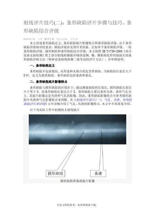
射线评片技巧(二):条形缺陷评片步骤与技巧、条形缺陷综合评级2015-04-18 分类:解决方案阅读(1246) 评论(0)本文讲述条形缺陷定义、条形缺陷底片影像特点和条形缺陷评级,由于条形缺陷评级相对较复杂,缺陷评级涉及到许多因素,比如单个条形缺陷评级、一组条形缺陷评级、圆形缺陷和条形缺陷综合评级,本文按照JB/T4730-2005《承压设备无损检测》第2部分射线检测篇详细讲述钢、镍、铜制熔化焊对接接头的条形缺陷评级方法(特种设备射线检测二级考试的评片方法),并举例说明。
一、条形缺陷定义条形缺陷不包括裂纹、未焊透和未熔合的危害性缺陷,当缺陷的长宽比大于3时,定义为条状缺陷。
条形缺陷包括条渣和条孔。
二、条形缺陷底片影像特点条形缺陷与圆形缺陷的区别在于:通过测量缺陷的长宽比,圆形缺陷长宽比小于等于3,而条形缺陷长宽比大于3。
条形缺陷主要以条形夹渣、条形气孔为主,其底片影像还是夹渣和气孔的影像。
因此,条形缺陷影像特点可参考圆形缺陷中夹渣和气孔影像特点来判断。
在《射线评片技巧(一):气孔、夹渣、夹钨的缺陷评片和评级》文中详细介绍了气孔、夹渣的影像特点,本文中不再重复介绍。
以下为实际工作中拍摄的X射线底片圆形缺陷和条渣底片影像条孔和条渣底片影像三、条形缺陷评级1、表12为JB/T4730.2-2005条形缺陷评级方法JB/T4730.2-2005条形缺陷评级表(1)I级不允许存在条形缺陷;(2)评定框内只有单个条形缺陷;若母材厚度24mm,缺陷长度13mm,II级允许最大长度为24/3=8mm<13mm,则超过II级;III级允许长度24×2/3=16mm>14mm,则该缺陷评为IIV级。
(3)评定框内存在一组条形缺陷;评级方法是先从低级别判定是否满足该条件,满足则评为该级别,不满足判断高级别条件。
若评定框内有条条形缺陷,母材厚度34mm,如下图为缺陷示意图。
条形缺陷示意图若假定评为II级,观察是否满足II级条件。
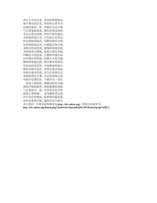
评片人员应注意, 适用标准要熟记.
观片像质放在先, 所有标记要齐全.
识别伪象第二件, 仔细区分也不难.
气孔图象最易看, 圆形浓黑边缘淡.
非金点状夹渣物, 形状不惦有棱边.
夹珠通常很少见, 白色底片有黑边.
咬边成线或成点, 似断似续常出现.
这种缺陷很好评, 位置就在熔合线.
未熔合的深度浅, 射线照相难发现.
未焊透是大缺陷, 影象大都呈直线.
间隙过小饨边厚, 位置就在缝中间.
内凹就在仰焊面, 间隙太大是关键.
横裂纵裂最危险, 纵向裂纹常相见.
有的直线有的弯, 中间稍宽两端尖.
裂纹未熔不允许, 若要发现评四级.
单面出现未焊透, 应以长深来区分.
未熔条渣区分难, 评定两者细心看.
夹渣评定测长短, 不能评为一级片.
一直线上条渣组, 测量间距是关键.
缺陷评级按板厚, 缺陷数量按条款.
气孔条渣在一起, 孔渣各自先评级.
级别之和再减一, 成为最终评定级.
评片综合技能高, 标准规范最重要.
定性定量和评级, 最终结论不能少.
本文摘自: 中国无损检测论坛() 详细出处请参考:/forum.php?mod=viewthread&tid=2403&extra=page%3D15。
焊缝射线照相底片的评判规律一、探伤人员要评片,四项指标放在先*,底片标记齐又正,铅字压缝为废片。
二、评片开始第一件,先找四条熔合线,小口径管照椭圆,根部都在圈里面。
三、气孔形象最明显,中心浓黑边缘浅,夹渣属于非金属,杂乱无章有棱边。
四、咬边成线亦成点,似断似续常相见,这个缺陷最好定,位置就在熔合线。
五、未焊透是大缺陷,典型图象成直线,间隙太小钝边厚,投影部位靠中间。
六、内凹只在仰焊面,间隙太大是关键,内凹未透要分清,内凹透度成弧线。
七、未熔合它斜又扁,常规透照难发现,它的位置有规律,都在坡口与层间。
八、横裂纵裂都危险,横裂多数在表面,纵裂分布范围广,中间稍宽两端尖。
九、还有一种冷裂纹,热影响区常发现,冷裂具有延迟性,焊完两天再拍片。
十、有了裂纹很危险,斩草除根保安全,裂纹不论长和短,全部都是Ⅳ级片。
十一、未熔和也很危险,黑度有深亦有浅,一旦判定就是它,亦是全部Ⅳ级片。
十二、危害缺陷未焊透,Ⅱ级焊缝不能有,管线根据深和长,容器跟着条渣走**。
十三、夹渣评定莫着忙,分清圆形和条状,长宽相比3为界,大于3倍是条状。
十四、气孔危害并不大,标准对它很宽大,长径折点套厚度,中间厚度插入法。
十五、多种缺陷大会合,分门别类先评级,2类相加减去Ⅰ,3类相加减Ⅱ级。
十六、评片要想快又准,下拜焊工当先生,要问诀窍有哪些,焊接工艺和投影。
注:*四项指标系底片的黑度、灵敏度、清晰度、灰雾度必须符合标准的要求。
**指单面焊的管线焊缝和双面焊的容器焊缝内未焊透的判定标准有网友来MAIL询问下列问题:现将解答过程贴上,也许有助于初学者掌握:题目是:一个钢焊缝,母材厚4mm,在300的底片上发现了一组夹渣,在一条直线上,分别长3mm和2mm,间距10mm,安JB-4730标准评级,答案是3级,我不知道过程是怎么样的,怎么得到这个结果.>首先该题条件不全,但并不影响解题,完整的解题应分为两部分,按JB4730-94标准,钢焊缝分为两部分,一则为对接焊缝,另一为钢管环缝,两者的判定条款不同。
射线底片评定口诀
一、探伤人员要评片,四项指标放在先*,底片标记齐又正,铅字压缝为废片。
二、评片开始第一件,先找四条熔合线,小口径管照椭圆,根部都在圈里面。
三、气孔形象最明显,中心浓黑边缘浅,夹渣属于非金属,杂乱无章有棱边。
四、咬边成线亦成点,似断似续常相见,这个缺陷最好定,位置就在熔合线。
五、未焊透是大缺陷,典型图像成直线,间隙太小钝边厚,投影部位*中间。
六、内凹只在仰焊面,间隙太大是关键,内凹未透要分清,内凹透度成弧线。
七、未熔合它斜又扁,常规透照难发现,它的位置有规律,都在坡口与层间。
八、横裂纵裂都危险,横裂多数在表面,纵裂分布范围广,中间稍宽两端尖。
九、还有一种冷裂纹,热影响区常发现,冷裂具有延迟性,焊完两天再拍片。
十、有了裂纹很危险,斩草除根保安全,裂纹不论长和短,全部都是Ⅳ级片。
十一、未熔和也很危险,黑度有深亦有浅,一旦判定就是它,亦是全部Ⅳ级片。
十二、危害缺陷未焊透,Ⅱ级焊缝不能有,管线根据深和长,容器跟着条渣走**。
十三、夹渣评定莫着忙,分清圆形和条状,长宽相比3为界,大于3倍是条状。
十四、气孔危害并不大,标准对它很宽大,长径折点套厚度,中间厚度插入法。
十五、多种缺陷大会合,分门别类先评级,2类相加减去Ⅰ,3类相加减Ⅱ级。
十六、评片要想快又准,下拜焊工当先生,要问诀窍有哪些,焊接工艺和投影。
注:*四项指标系底片的黑度、灵敏度、清晰度、灰雾度必须符合标准的要求。
**指单面焊的管线焊缝和双面焊的容器焊缝内未焊透的判定标准。
(转自筑龙网)。
焊缝射线照相底片的评判规律一、探伤人员要评片,四项指标放在先*,底片标记齐又正,铅字压缝为废片。
二、评片开始第一件,先找四条熔合线,小口径管照椭圆,根部都在圈里面。
三、气孔形象最明显,中心浓黑边缘浅,夹渣属于非金属,杂乱无章有棱边。
四、咬边成线亦成点,似断似续常相见,这个缺陷最好定,位置就在熔合线。
五、未焊透是大缺陷,典型图象成直线,间隙太小钝边厚,投影部位靠中间。
六、内凹只在仰焊面,间隙太大是关键,内凹未透要分清,内凹透度成弧线。
七、未熔合它斜又扁,常规透照难发现,它的位置有规律,都在坡口与层间。
八、横裂纵裂都危险,横裂多数在表面,纵裂分布范围广,中间稍宽两端尖。
九、还有一种冷裂纹,热影响区常发现,冷裂具有延迟性,焊完两天再拍片。
十、有了裂纹很危险,斩草除根保安全,裂纹不论长和短,全部都是Ⅳ级片。
十一、未熔和也很危险,黑度有深亦有浅,一旦判定就是它,亦是全部Ⅳ级片。
十二、危害缺陷未焊透,Ⅱ级焊缝不能有,管线根据深和长,容器跟着条渣走**。
十三、夹渣评定莫着忙,分清圆形和条状,长宽相比3为界,大于3倍是条状。
十四、气孔危害并不大,标准对它很宽大,长径折点套厚度,中间厚度插入法。
十五、多种缺陷大会合,分门别类先评级,2类相加减去Ⅰ,3类相加减Ⅱ级。
十六、评片要想快又准,下拜焊工当先生,要问诀窍有哪些,焊接工艺和投影。
注:*四项指标系底片的黑度、灵敏度、清晰度、灰雾度必须符合标准的要求。
**指单面焊的管线焊缝和双面焊的容器焊缝内未焊透的判定标准。
Radiograph Interpretation - WeldsIn addition to producing high quality radiographs, the radiographer must also be skilled in radiographic interpretation. Interpretation of radiographs takes place in three basic steps which are (1) detection, (2) interpretation, and (3) evaluation. All of these steps make use of the radiographer's visual acuity. Visual acuity is the ability to resolve a spatial pattern in an image. The ability of an individual to detect discontinuities in radiography is also affected by the lighting condition in the place of viewing, and the experience level for recognizing various features in the image. The following material was developed to help students develop an understanding of the types of defects found in weldments and how they appear in a radiograph.DiscontinuitiesDiscontinuities are interruptions in the typical structure of a material. These interruptions may occur in the base metal, weld material or "heat affected" zones. Discontinuities, which do not meet the requirements of the codes or specification used to invoke and control an inspection, are referred to as defects.General Welding DiscontinuitiesThe following discontinuities are typical of all types of welding.Cold lap is a condition where the weld filler metal does not properly fuse with the base metal or the previous weld pass material (interpass cold lap). The arc does not melt the base metal sufficiently and causes the slightly molten puddle to flow into base material without bonding.Porosity气孔is the result of gas entrapment in the solidifying metal. Porosity can take many shapes on a radiograph but often appears as dark round or irregular spots or specks appearing singularly, in clusters or rows. Sometimes porosity is elongated and may have the appearance of having a tail This is the result of gas attempting to escape while the metal is still in a liquid state and is called wormhole porosity. All porosity is a void in the material it will have a radiographic density more than the surrounding area..Cluster porosity链状气孔is caused when flux coated electrodes are contaminated with moisture. The moisture turns into gases when heated and becomes trapped in the weld during the welding process. Cluster porosity appear just like regular porosity in the radiograph but the indications will be grouped close together.Slag inclusions夹渣 are nonmetallic solid material entrapped in weld metal or between weld and base metal. In a radiograph, dark, jagged asymmetrical shapes within the weld or along the weld joint areas are indicative of slag inclusions.Incomplete penetration (IP) or lack of penetration (LOP)未焊透occurs when the weld metal fails to penetrate the joint. It is one of the most objectionable weld discontinuities. Lack of penetration allows a natural stress riser from which a crack may propagate. The appearance on a radiograph is a dark area with well-defined, straight edges that follows the land or root face down the center of the weldment.Incomplete fusion未熔合is a condition where the weld filler metal does not properly fuse with the base metal. Appearance on radiograph: usually appears as a dark line or lines oriented in the direction of the weld seam along the weld preparation or joining area.Internal concavity or suck back内凹或吸入is condition where the weld metal has contracted as it cools and has been drawn up into the root of the weld. On a radiograph it looks similar to lack of penetration but the line has irregular edges and it is often quite wide in the center of the weld image.Internal or root undercut内部或根部咬边is an erosion of the base metal next to the root of the weld. In the radiographic image it appears as a dark irregular line offset from the centerline of the weldment. Undercutting is not as straight edged as LOP because it does not follow a ground edge.External or crown undercut外部或顶部咬边is an erosion of the base metal next to the crown of the weld. In the radiograph, it appears as a dark irregular line along the outside edge of the weld area.Offset or mismatch错边are terms associated with a condition where two pieces being welded together are not properly aligned. The radiographic image is a noticeable difference in density between the two pieces. The difference in density is caused by the difference in material thickness. The dark, straight line is caused by failure of the weld metal to fuse with the land area.Inadequate weld reinforcement未填满is an area of a weld where the thickness of weld metal deposited is less than the thickness of the base material. It is very easy to determine by radiograph if the weld has inadequate reinforcement, because the image density in the area of suspected inadequacy will be more (darker) than the image density of the surrounding base material.Excess weld reinforcement增强余高is an area of a weld, which has weld metal added in excess of that specified by engineering drawings and codes. The appearance on a radiograph is a localized, lighter area in the weld. A visual inspection will easily determine if the weld reinforcement is in excess of that specified by the individual code involved in the inspection.Cracking裂纹can be detected in a radiograph only the crack is propagating in a direction that produced a change in thickness that is parallel to the x-ray beam. Cracks will appearas jagged and often very faint irregular lines. Cracks can sometimes appearing as "tails" on inclusions or porosity.Discontinuities in TIG weldsThe following discontinuities are peculiar to the TIG welding process. These discontinuities occur in most metals welded by the process including aluminum and stainless steels. The TIG method of welding produces a clean homogeneous weld which when radiographed is easily interpreted.Tungsten inclusions. 夹钨Tungsten is a brittle and inherently dense material used in the electrode in tungsten inert gas welding. If improper welding procedures are used, tungsten may be entrapped in the weld. Radiographically, tungsten is more dense than aluminum or steel; therefore, it shows as a lighter area with a distinct outline on the radiograph.Oxide inclusions夹氧化物are usually visible on the surface of material being welded (especially aluminum). Oxide inclusions are less dense than the surrounding materials and, therefore, appear as dark irregularly shaped discontinuities in the radiograph.Discontinuities in Gas Metal Arc Welds (GMAW)The following discontinuities are most commonly found in GMAW welds.Whiskers are short lengths of weld electrode wire, visible on the top or bottom surface of the weld or contained within the weld. On a radiograph they appear as light, "wire like" indications.Burn through (icicles) results when too much heat causes excessive weld metal to penetrate the weld zone. Lumps of metal sag through the weld creating a thick globular condition on the back of the weld. On a radiograph, burn through appears as dark spots surrounded by light globular areas.welld-02 (Incomplete Root Fusion、根部未熔合)—welld-03 (Insuffucient Reinforcement、增强高)——welld-04 (Excess Root Penetration、根部焊瘤)——welld-05 (External Undercut、外部咬肉)——welld-06 (Internal Undercut、内部咬肉)——welld-07 (Root Concavity、根部凹陷)——welld-08 (Burn Through、烧穿)——welld-09 (Isolated Slag Inclusion、单个的夹渣)——welld-10 (Wagon Track - Slag Line、线状夹渣)——welld-11 (Interrun Fusion、内部未熔合)——welld-12 (Lack of Sidewall Fusion、内侧未熔合)——welld-13 (Porosity、气孔)——welld-14 (Cluster Porosity、链状气孔)——welld-15 (Hollow Bead、夹珠)——welld-16 (Transverse Crack、横向裂纹)——welld-17 (Centerline Crack、中心线裂纹)——welld-18 (Root Crack、根部裂纹)——welld-19 (Tungsten Inclusion)夹钨—。
焊缝射线照相底片的评判规律之袁州冬雪创作一、探伤人员要评片,四项指标放在先*,底片标识表记标帜齐又正,铅字压缝为废片. 二、评片开端第一件,先找四条熔合线,小口径管照椭圆,根部都在圈外面. 三、气孔形象最分明,中心浓黑边沿浅,夹渣属于非金属,杂乱无章有棱边. 四、咬边成线亦成点,似断似续常相见,这个缺陷最好定,位置就在熔合线. 五、未焊透是大缺陷,典型图象成直线,间隙太小钝边厚,投影部位靠中间.六、内凹只在仰焊面,间隙太大是关键,内凹未透要分清,内凹透度成弧线. 七、未熔合它斜又扁,惯例透照难发现,它的位置有规律,都在坡口与层间. 八、横裂纵裂都危险,横裂多数在概况,纵裂分布范围广,中间稍宽两头尖. 九、还有一种冷裂纹,热影响区常发现,冷裂具有延迟性,焊完两天再拍片. 十、有了裂纹很危险,斩草除根保平安,裂纹不管长和短,全部都是Ⅳ级片. 十一、未熔和也很危险,黑度有深亦有浅,一旦断定就是它,亦是全部Ⅳ级片. 十二、危害缺陷未焊透,Ⅱ级焊缝不克不及有,管线根据深和长,容器跟着条渣走**. 十三、夹渣评定莫着忙,分清圆形和条状,长宽相比3为界,大于3倍是条状. 十四、气孔危害其实不大,尺度对它很广大,长径折点套厚度,中间厚度拔出法. 十五、多种缺陷大会合,分门别类先评级,2类相加减去Ⅰ,3类相加减Ⅱ级. 十六、评片要想快又准,下拜焊工当先生,要问窍门有哪些,焊接工艺和投影. 注:*四项指标系底片的黑度、活络度、清晰度、灰雾度必须符合尺度的要求. **指单面焊的管线焊缝和双面焊的容器焊缝内未焊透的断定尺度.Radiograph Interpretation - WeldsIn addition to producing high quality radiographs, the radiographer must also be skilled in radiographic interpretation. Interpretation of radiographs takes place in three basic steps which are (1) detection, (2) interpretation, and (3) evaluation. All of these steps make use of the radiographer's visual acuity. Visual acuity is the ability to resolve a spatial pattern in an image. The ability of an individual to detect discontinuities in radiography is also affected by the lighting condition in the place of viewing, and the experience level for recognizing various features in the image. The following material was developed to help students develop an understanding of the types of defects found in weldments and how they appear in a radiograph.DiscontinuitiesDiscontinuities are interruptions in the typical structure of a material. These interruptions may occur in the base metal, weld material or "heat affected" zones.Discontinuities, which do not meet the requirements of the codes or specification used to invoke and control an inspection, are referred to as defects.General Welding DiscontinuitiesThe following discontinuities are typical of all types of welding.Cold lap is a condition where the weld filler metal does not properly fuse with the base metal or the previous weld pass material (interpass cold lap). The arc does not melt the base metal sufficiently and causes the slightly molten puddle to flow into base material without bonding.Porosity气孔is the result of gas entrapment in the solidifying metal. Porosity can take many shapes on a radiograph but often appears as dark round or irregular spots or specks appearing singularly, in clusters or rows. Sometimes porosity is elongated and may have the appearance of having a tail This is the result of gas attempting to escape while the metal is still in a liquid state and is called wormhole porosity. All porosity is a void in thematerial it will have a radiographic density more than the surrounding area..Cluster porosity链状气孔is caused when flux coated electrodes are contaminated with moisture. The moistureturns into gases when heated and becomes trapped in the weld during the welding process. Cluster porosity appear justlike regular porosity in the radiograph but the indications will be grouped close together.Slag inclusions夹渣 are nonmetallic solid materialentrapped in weld metal or between weld and base metal. In a radiograph, dark, jagged asymmetrical shapes within the weld or along the weld joint areas are indicative of slag inclusions.Incomplete penetration (IP) or lack of penetration (LOP)未焊透occurs when the weld metal fails to penetrate the joint.It is one of the most objectionable weld discontinuities. Lack of penetration allows a natural stress riser from which a crack may propagate. The appearance on a radiograph is a dark area with well-defined, straight edges that follows the land or root face down the center of the weldment. Incomplete fusion未熔合is a condition where the weld filler metal does not properly fuse with the base metal. Appearance on radiograph: usually appears as a dark line or lines oriented in the direction of the weld seam along the weld preparation or joining area.Internal concavity or suck back内凹或吸入is condition where the weld metal has contracted as it cools and has been drawn up into the root of the weld. On a radiograph it looks similar to lack of penetration but the line has irregular edges and it is often quite wide in the center of the weld image.Internal or root undercut外部或根部咬边is an erosion of the base metal next to the root of the weld. In the radiographic image it appears as a dark irregular line offset from the centerline of the weldment. Undercutting is not as straight edged as LOP because it does not follow a ground edge.External or crown undercut外部或顶部咬边is an erosion of the base metal next to the crown of the weld. In the radiograph, it appears as a dark irregular line along the outside edge of the weld area.Offset ormismatch错边are terms associated with a condition where two pieces being welded together are not properly aligned. The radiographic image is a noticeable differencein density between the two pieces. The difference in density is caused by the difference in material thickness. The dark, straight line is caused by failure of the weld metal to fuse with the land area.Inadequate weld reinforcement未填满is an area of a weld where the thickness of weld metal deposited is less than the thickness of the base material. It is very easy to determine by radiograph if the weld has inadequate reinforcement, because the image density in the area of suspected inadequacy will be more (darker) than the image density of the surrounding base material.Excess weld reinforcement增强余高is an area of a weld, which has weld metal added in excess of that specified by engineering drawings and codes. The appearance on aradiograph is a localized, lighter area in the weld. Avisual inspection will easily determine if the weld reinforcement is in excess of that specified by the individual code involved in the inspection.Cracking裂纹can be detected in a radiograph only the crack is propagating in a direction that produced a change in thickness that is parallel to the x-ray beam. Cracks will appearas jagged and often very faint irregular lines. Cracks can sometimes appearing as "tails" on inclusions or porosity.Discontinuities in TIG weldsThe following discontinuities are peculiar to the TIG welding process. These discontinuities occur in most metals welded by the process including aluminum and stainless steels. The TIG method of welding produces a clean homogeneous weld which when radiographed is easily interpreted.Tungsten inclusions. 夹钨Tungsten is a brittle and inherently dense material used in the electrode in tungsten inert gas welding. If improper welding procedures are used, tungsten may be entrapped in the weld. Radiographically,tungsten is more dense than aluminum or steel; therefore, it shows as a lighter area with a distinct outline on the radiograph.Oxide inclusions夹氧化物are usually visible on the surface of material being welded (especially aluminum). Oxide inclusions are less dense than the surrounding materials and, therefore, appear as dark irregularly shaped discontinuities in the radiograph.Discontinuities in Gas Metal Arc Welds (GMAW)The following discontinuities are most commonly found in GMAW welds.Whiskers are short lengths of weld electrode wire, visibleon the top or bottom surface of the weld or contained within the weld. On a radiograph they appear as light, "wire like" indications.Burn through (icicles) results when too much heat causes excessive weld metal to penetrate the weld zone. Lumps of metal sag through the weld creating a thick globularcondition on the back of the weld. On a radiograph, burnthrough appears as dark spots surrounded by light globular areas.welld-02 (Incomplete Root Fusion、根部未熔合)welld-03 (Insuffucient Reinforcement、增强高)welld-04 (Excess Root Penetration、根部焊瘤)welld-05 (External Undercut、外部咬肉)welld-06 (Internal Undercut、外部咬肉)welld-07 (Root Concavity、根部凹陷)welld-08 (Burn Through、烧穿)welld-09 (Isolated Slag Inclusion、单个的夹渣)welld-10 (Wagon Track - Slag Line、线状夹渣)welld-11 (Interrun Fusion、外部未熔合)welld-12 (Lack of Sidewall Fusion、内侧未熔合)welld-13 (Porosity、气孔)welld-14 (Cluster Porosity、链状气孔)welld-15 (Hollow Bead、夹珠)welld-16 (Transverse Crack、横向裂纹) welld-17 (Centerline Crack、中心线裂纹) welld-18 (Root Crack、根部裂纹)welld-19 (Tungsten Inclusion)夹钨。
射线检测评片口诀(完整版)
一、探伤人员要评片,四项指标放在先*,底片标记齐又正,铅字压缝为废片。
二、评片开始第一件,先找四条熔合线,***管照椭圆,根部都在圈里面。
三、气孔形象最明显,中心浓黑边缘浅,夹渣属于非金属,杂乱无章有棱边。
四、咬边成线亦成点,似断似续常相见,这个缺陷最好定,位置就在熔合线。
五、未焊透是大缺陷,典型图象成直线,间隙太小钝边厚,投影部位靠中间。
六、内凹只在仰焊面,间隙太大是关键,内凹未透要分清,内凹透度成弧线。
七、未熔合它斜又扁,常规透照难发现,它的位置有规律,都在坡口与层间。
八、横裂纵裂都危险,横裂多数在表面,纵裂分布范围广,中间稍宽两端尖。
九、还有一种冷裂纹,热影响区常发现,冷裂具有延迟性,焊完两天再拍片。
十、有了裂纹很危险,斩草除根保安全,裂纹不论长和短,全部都是Ⅳ**。
十一、未熔和也很危险,黑度有深亦有浅,一旦判定就是它,亦是全部Ⅳ**。
十二、危害缺陷未焊透,Ⅱ级焊缝不能有,管线根据深和长,容器跟着条渣走**。
十三、夹渣评定莫着忙,分清圆形和条状,长宽相比3为界,大于3倍是条状。
十四、气孔危害并不大,标准对它很宽大,长径折点套厚度,中间厚度插入法。
十五、多种缺陷大会合,分门别类先评级,2类相加减去Ⅰ,3类相加减Ⅱ级。
十六、评片要想快又准,下拜焊工当先生,要问诀窍有哪些,焊接工艺和投影。
注:*四项指标系底片的黑度、灵敏度、清晰度、灰雾度必须符合标准的要求。
**指单面焊的管线焊缝和双面焊的容器焊缝内未焊透的判定标准。
无损检测。
焊缝射线照相底片的评判小窍门
一、探伤人员要评片,四项指标放在先*,底片标记齐又正,铅字压缝为废片。
二、评片开始第一件,先找四条熔合线,小口径管照椭圆,根部都在圈里面。
三、气孔形象最明显,中心浓黑边缘浅,夹渣属于非金属,杂乱无章有棱边。
四、咬边成线亦成点,似断似续常相见,这个缺陷最好定,位置就在熔合线。
五、未焊透是大缺陷,典型图象成直线,间隙太小钝边厚,投影部位靠中间。
六、内凹只在仰焊面,间隙太大是关键,内凹未透要分清,内凹透度成弧线。
七、未熔合它斜又扁,常规透照难发现,它的位置有规律,都在坡口与层间。
八、横裂纵裂都危险,横裂多数在表面,纵裂分布范围广,中间稍宽两端尖。
九、还有一种冷裂纹,热影响区常发现,冷裂具有延迟性,焊完两天再拍片。
十、有了裂纹很危险,斩草除根保安全,裂纹不论长和短,全部都是Ⅳ级片。
十一、未熔和也很危险,黑度有深亦有浅,一旦判定就是它,亦是全部Ⅳ级片。
十二、危害缺陷未焊透,Ⅱ级焊缝不能有,管线根据深和长,容器跟着条渣走**。
十三、夹渣评定莫着忙,分清圆形和条状,长宽相比3为界,大于3倍是条状。
十四、气孔危害并不大,标准对它很宽大,长径折点套厚度,中间厚度插入法。
十五、多种缺陷大会合,分门别类先评级,2类相加减去Ⅰ,3类相加减Ⅱ级。
十六、评片要想快又准,下拜焊工当先生,要问诀窍有哪些,焊接工艺和投影。
注:*四项指标系底片的黑度、灵敏度、清晰度、灰雾度必须符合标准的要求。
**指单面焊的管线焊缝和双面焊的容器焊缝内未焊透的判定标准。
射线评片技巧(一):气孔、夹渣、夹钨射线底片影像特点
2015-04-17 分类:解决方案阅读(4103) 评论(0)
按照JB/T4730-2005《承压设备无损检测》第2部分射线(点击下载:
NB/T47013.1~13-2015标准)检测篇介绍,焊接接头中的缺陷按性质区分为裂纹、未熔合、未焊透、条形缺陷和圆形缺陷五类。
在《射线检测评片》栏目中将介绍该五类性质的缺陷成因、缺陷评片技巧、评级方法,分享在工作中遇见的射线检测案例。
本文介绍圆形缺陷(气孔、密集气孔、夹渣、夹钨)评片技巧和缺陷定量评级。
一、圆形缺陷的评片
缺陷长宽之比小于等于3(L/N<=3),且非裂纹、未焊透和未熔合危害性缺陷。
对接接头焊缝常见的圆形缺陷包括圆形气孔、非金属夹渣、夹钨等性质缺陷。
圆形缺陷示意图
1、气孔
(1)气孔成因
在《焊缝气孔形成机理及超声检测波形特性》文中详细介绍了焊缝气孔形成的原因。
气孔分为单个气孔和密集性气孔。
气孔降低了焊缝的金属致密性,降低焊接接头的强度、韧性等力学性能。
(2)气孔射线成像特点
气孔部充满气体,射线穿过气孔几乎不会形成材质衰减。
在射线底片上气孔呈暗色斑点,中心黑度较大。
单个气孔边缘较浅平滑过渡,轮廓规则较清晰,密集气孔成团状。
气孔大多是球形的,也可以有其它形状,气体的形状与焊接条件密切有关。
单个气孔缺陷
密集性气孔
2、非金属夹渣
(1)夹渣成因
焊缝夹渣形成原因主要有以下几点:
•在焊接每层焊道层间清渣不干净;
•焊接电流过小、焊接速度过快;
•焊接操作过程不当;
•母材坡口设计加工不当;
•液态金属冷却速度过快等;
第一条是焊缝产生夹渣的直接原因,第二到第五条原因是由于焊渣在液态金属中浮渣不及时而残留在焊缝中。
焊缝中存在非金属夹渣,当焊缝承受应力过程中在夹渣周围会形成裂纹扩展,裂纹发展到一定程度焊缝开裂。
夹渣严重降低了焊接件强度、韧性等力学性能。
(2)夹渣射线成像特点
焊缝金属包裹着非金属夹杂物形成夹渣、射线穿过夹渣有一定的衰减,但远远小于焊缝金属对射线的衰减。
射线底片上夹渣呈暗色斑点,黑度分布无规律,轮廓不圆滑不规则,小点状夹渣轮廓较不清晰。
非金属夹渣
3、夹钨
(1)夹钨成因
钨极承载电流的能力较差,过大的电流会引起钨极熔化和蒸发,其微粒有可能进入熔池,形成夹钨。
(2)夹渣射线成像
金属钨射线的衰减系数比钢大,透过金属钨后的射线能量比钢低,胶片吸收射线产生的光电子更少。
在底片上成亮色,轮廓清晰。
夹钨缺陷
以下为实际工作中的射线底片
夹渣和圆形气孔缺陷底片
夹渣气孔夹钨缺陷底片
圆形缺陷(链状气孔)底片
密集气孔缺陷底片
双影双壁透照圆形缺陷底片
虫状气孔底片
二、圆形缺陷的评级
圆形缺陷的评级参考JB/T4730-2005《承压设备无损检测》第2部分射线检测标准讲解,该标准规定的评级方法:
“5.1.5.1圆形缺陷用圆形缺陷评定区进行质量分级评定,圆形缺陷评定区为一个与焊缝平行的矩形,其尺寸见表8。
圆形缺陷评定区应选在缺陷最严重的区域。
5.1.5.2 在圆形缺陷评定区或与圆形缺陷评定区边界线相割的缺陷均应划入评定区。
将评定区的缺陷按表9的规定换算为点数,按表10的规定评判焊接接头的质量级别。
“
表8 缺陷评定框
表9 缺陷点数换算表
表10 缺陷评级表
举例说明:
例子:若母材公称厚度(母材测量厚度)为19mm,首先判断底片上的缺陷非裂纹、未焊透和未熔合危害性缺陷。
再根据表8采用10×10的正方形评定框,框住最严重的部位,测量缺陷的长度。
若在该评定框分别有编号为A、B、C、D 四个缺陷,测量长度分别为3mm、4mm、2mm、5mm。
根据表9换算成点数分别为3个、6个、2个、10个,总共点数相加为3+6+2+10=21个点。
母材厚度为18mm,
.
共换算为21个点大于III的最大点数18,根据表10评为IV级。
若验收等级为III级,则该焊接件焊缝质量不合格。
备注:
1、>1-2表示,大于1且小于等于2(该围包含2不包含1)。
2、由于材质或结构等原因,进行返修可能会产生不利后果的焊接接头,经合同各方同意,各级别的圆形缺陷点数可放宽1点~2点。
(比如在测量圆形缺陷点在换算成点数,若点数为18,母材厚度为19mm,严格按照JB/T4730.2-2005标准的评级表评为IV级。
若放宽1点,则为17点评为III。
)
3、对致密性要求高的焊接接头,制造方底片评定人员应考虑将圆形缺陷的黑度作为评级的依据,将黑度大的圆形缺陷定义为深孔缺陷,当焊接接头存在深孔缺陷时,焊接接头质量评为Ⅳ级。
4、如下表中所示,母材厚度在规定围不计点数的缺陷尺寸。
若母材公称厚度为23mm,当缺陷长径小于0.5mm,则该缺陷不计入点数换算。
缺陷不计点数的缺陷尺寸
.。