脆性岩石水岩耦合的试验研究
- 格式:pdf
- 大小:212.75 KB
- 文档页数:3
岩石脆性研究现状岩石脆性研究是岩石力学领域的一个重要研究方向之一,也是地质灾害预防和控制、岩土工程设计以及能源、水资源等开发利用的重要基础。
本文将从研究现状、研究方法、影响因素及应用前景等方面进行阐述。
一、研究现状脆性是指岩石在受到应力作用下发生非线性变形的现象。
岩石的脆性状况与岩石的抗压强度、抗剪强度、断裂韧度和应力集中系数等参数密切相关。
在岩石的力学破坏中,脆性破坏是一种常见的破坏形式。
因此,研究岩石的脆性特征对于预测岩石的力学破坏特征具有重要的意义。
岩石脆性的研究涉及到岩石力学、地质力学、材料力学、力学、科学计算等众多学科领域,其研究内容主要包括脆性破坏机理、脆性参数的测试、评价和预测、脆性与断裂的关系等。
目前,国内外对岩石脆性研究的主要方法包括实验室试验、数值模拟以及野外测试等。
1.实验室试验实验室试验是研究岩石脆性的一种直接方法。
这种方法主要利用岩石试样进行压缩试验、剪切试验、间接剪切试验,进而测定岩石的脆性参数以及与其它力学参数之间的关系。
脆性参数的测定包括岩石的弹性模量、强度、变形模量、断裂模量、岩石断裂面的粗糙度、开裂程度等。
这些参数主要用于描述岩石脆性的状况和断裂的发生特征。
实验室试验通过建立岩石的力学模型,定量研究了岩石的破坏过程,从而提高了对岩石脆性的认识和理解。
2.数值模拟数值模拟是一种先进的岩石脆性研究方法。
数值模拟主要利用离散元、有限元、边界元等数值分析方法,对岩石破坏行为进行模拟和预测。
数值模拟方法具有基础理论成熟,测试全面、直观等优点,可用于研究岩石在各种应力状态下的脆性破坏本质,分析岩石的破坏过程和能量耗散规律,预测钻孔、隧道开挖、水力压裂等工程中岩石的破坏状态和预定荷载的合理值。
3.野外测试野外测试是在岩石破裂现场进行的,通过现场勘探、取样和实测等手段,对岩石的脆性状态进行测试和分析。
野外测试方法根据实际场景和需要,综合运用多种现场测试手段,如声波检测、超声波检测、地下雷达检测、卫星遥感检测、地震监测等,对岩石的脆性状态进行直接测量和分析。
岩石脆性研究现状岩石脆性是指岩石在外部作用力下发生断裂和破碎的能力。
脆性是岩石力学中的重要参数,在土木工程、矿业工程、石油工程、地质工程等领域中具有广泛的应用。
研究岩石脆性有助于预测岩石在不同应力状态下的断裂模式和破碎机理,提高工程设计的精度和可靠性。
目前,岩石脆性的研究主要包括实验测定、理论分析和数值模拟三个方面。
实验测定是研究岩石脆性最常用的方法。
其基本思想就是在实验室中对一定大小的岩石样品施加不同大小的应力,观察其如何响应。
实验测定岩石脆性的方法主要有弯曲试验法、压缩试验法、拉伸试验法等。
其中,弯曲试验法是最常用的方法之一。
在弯曲试验中,岩石样品放置在两个支撑点之间,上方施加相反方向的力矩,使其产生曲率。
通过测定样品的弯曲应变和裂纹扩展情况,可以获得其断裂韧度和脆性等力学性能。
不过,实验测定存在很多限制。
首先,它只能获得特定岩石样品的断裂性质,不能代表全岩的力学性质。
其次,实验测定过程中必须控制各种条件,如温度、湿度、应变速率等,且需要大量的测试时间和经济成本。
因此,实验测定方法并不是最为优越的方法。
理论分析是研究岩石脆性的另一个重要方法。
这种方法主要是基于半经验的理论,包括微裂纹力学、破碎力学等。
微裂纹力学是最为成功的理论之一,它认为岩石是由天然裂纹或微裂缝系统组成的,而应力场在这些裂缝周围引起的高应力集中会扩大并破坏它们。
破碎力学是在微裂纹力学基础上发展起来的,它主要关注岩石破碎过程中裂纹扩展规律和裂纹网络组织结构的变化。
数值模拟是近年来岩石脆性研究中的重要手段之一。
通过建立岩石样品的离散元模型,采用计算机模拟技术,模拟岩石样品在受力下的变形、断裂和破碎过程。
相比于实验测定和理论分析,数值模拟具有较好的灵活性和可操作性。
利用数值模拟可以模拟多种应力状态和岩石类型的脆性行为,并能在模拟过程中观察到岩石断裂和裂纹扩展的微观过程。
总的来说,岩石脆性研究的现状是多元化的,综合应用实验测定、理论分析和数值模拟等方法,探究岩石的力学性质和断裂破碎机理,有助于提高矿山、地质、土木和石油等工程领域的设计和安全水平。
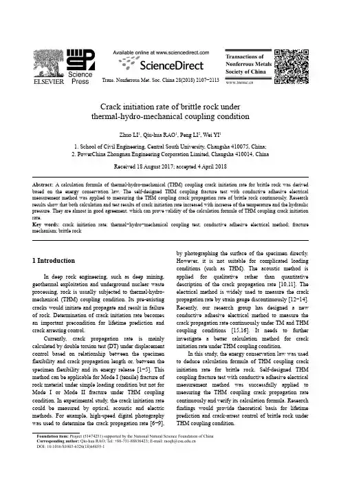
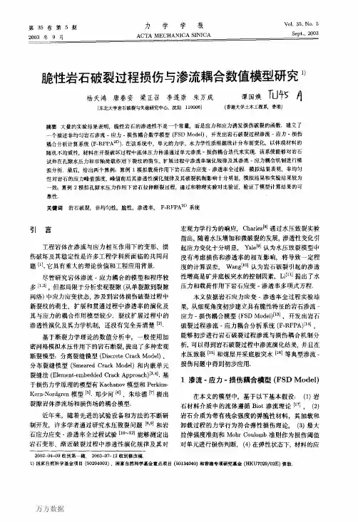
Trans. Nonferrous Met. Soc. China 28(2018) 2107−2113Crack initiation rate of brittle rock underthermal-hydro-mechanical coupling conditionZhuo LI1, Qiu-hua RAO1, Peng LI2, Wei YI11. School of Civil Engineering, Central South University, Changsha 410075, China;2. PowerChina Zhongnan Engineering Corporation Limited, Changsha 410014, ChinaReceived 18 August 2017; accepted 4 April 2018Abstract:A calculation formula of thermal-hydro-mechanical (THM) coupling crack initiation rate for brittle rock was derived based on the energy conservation law. The self-designed THM coupling fracture test with conductive adhesive electrical measurement method was applied to measuring the THM coupling crack propagation rate of brittle rock continuously. Research results show that both calculation and test results of crack initiation rate increased with increase of the temperature and the hydraulic pressure. They are almost in good agreement, which can prove validity of the calculation formula of THM coupling crack initiation rate.Key words: crack initiation rate; thermal−hydro−mechanical coupling test; conductive adhesive electrical method; fracture mechanism; brittle rock1 IntroductionIn deep rock engineering, such as deep mining,geothermal exploitation and underground nuclear wasteprocessing, rock is usually subjected to thermal-hydro-mechanical (THM) coupling condition. Its pre-existingcracks would initiate and propagate and result in failureof rock. Determination of crack initiation rate becomesan important precondition for lifetime prediction andcrack arresting control.Currently, crack propagation rate is mainlycalculated by double torsion test (DT) under displacementcontrol based on relationship between the specimenflexibility and crack propagation length or, between thespecimen flexibility and its energy release [1−5]. Thismethod can be applicable for Mode I (tensile) fracture ofrock material under simple loading condition but not forMode I or Mode II fracture under THM couplingcondition. In experimental study, the crack initiation ratecould be measured by optical, acoustic and electricmethods. For example, high-speed digital photographywas used to determine the crack propagation rate [6−9],by photographing the surface of the specimen directly.However, it is not suitable for complicated loadingconditions (such as THM). The acoustic method isapplied for qualitative rather than quantitativedescription of the crack propagation rate [10,11]. Theelectrical method is widely used to measure the crackpropagation rate by strain gauge discontinuously [12−14].Recently, our research group has designed a newconductive adhesive electrical method to measure thecrack propagation rate continuously under TM and THMcoupling conditions [15,16]. It needs to furtherinvestigate a better calculation method for crackinitiation rate under THM coupling condition.In this study, the energy conservation law was usedto deduce calculation formula of THM coupling crackinitiation rate for brittle rock. Self-designed THMcoupling fracture test with conductive adhesive electricalmeasurement method was successfully applied tomeasuring the THM coupling crack propagation ratecontinuously and verify its calculation formula. Researchfindings would provide theoretical basis for lifetimeprediction and crack-arrest control of brittle rock underTHM coupling condition.Foundation item: Project (51474251) supported by the National Natural Science Foundation of ChinaCorresponding author: Qiu-hua RAO; Tel: +86-731-88836423; E-mail: raoqh@DOI:10.1016/S1003-6326(18)64855-1Zhuo LI, et al/Trans. Nonferrous Met. Soc. China 28(2018) 2107−211321082 Formula derivation of crack initiation rate under THM coupling condition2.1 Calculation modelFigure 1 shows a standard rock specimen (D =50 mm and L =100 mm) of an inclined penetrating crack(2a =30 mm and α=45°), which is subjected totemperature T , hydraulic pressure p H on the crack surface,axial pressure p L and confining pressure p M , i.e., THMcoupling load.Fig. 1 Rock specimen under THM coupling condition2.2 Calculation formulaFigure 2 illustrates a typical stress −strain curve ofthe pre-crack rock specimen under THM coupling load.It is usually classified into four stages: non-linearcompaction (OA ), elastic deformation (AB ), damage (BC ) and failure (CD ). In the damage stage (BC ), crackpropagation is dominant regardless of small plasticdeformation for the brittle rock specimen.Fig. 2 Schematic diagram of stress −strain curveUnder THM coupling condition, total work of external load (W THM ) consists of heat energy (W T ), hydraulic work (W H ), axial compression work (W L ) and confining pressure work (W M ), i.e.,THM T H L M = W W W W W =+++T H H L L M M d +d d d E T p l p l p l α++⎰⎰⎰⎰ (1)where αT is the coefficient of thermal expansion, E is theelastic modulus, T is the temperature, l H , l L and l M correspond to displacements caused by hydraulic pressure, axial pressure and confining pressure,respectively.In special case, when the specific temperature isconstant during process of THM loading condition,Eq. (1) becomes THM H H L L M M d d d W p l p l p l =++⎰⎰⎰ (2) According to energy method, the total work of external load (W THM ) is completely exchanged into storage energy of the rock specimen, including dissipation energy of non-linear compaction (U d ), elastic strain energy (U e ) [17] and fracture surface energy Γ [18] as follows:THM d e THM d e 222e 13133+ (when < before the crack initiation)++ (when after the crack initiation)122(2)d 2d 2d 2d B B W U U W U U U VE G A Gb aεεΓεεσσμσσσΓ=⎧⎪⎪⎪=≥⎪⎨⎪⎪⎡⎤=+-+⎣⎦⎪⎪==⎩⎰ (3) where εB is the critical strain at crack initiation point B , σ1 is the principal stress, σ3 is the confining stress, V is the volume of rock specimen, G is the energy release rate, A is the crack area, a and b are crack length and crack width, respectively.Since b is almost unchanged at the initial stage of BC , it can be regarded as a constant and obtained by geometrical relation of the pre-crack rock specimen (Fig. 3).b = (4)Fig. 3 Determination of crack width at crack tip3 Determination of crack initiation rate3.1 THM testTHM test was used to determine the energy release rate G and dissipation energy of non-linear compactionZhuo LI, et al/Trans. Nonferrous Met. Soc. China 28(2018) 2107−2113 2109 stage U d in order to calculate the crack initiation rate v i.Rock material adopted in this study is red sandstone.Tables 1 and 2 list its main mechanical parameters atroom temperature (including elastic modulus E, Poissonratio v, tensile strength σt, compressive strength σc,cohension C and internal friction angle φ) and elasticmodulus E and fracture toughness (K IC and K IIC) atdifferent temperatures, which are obtained by testingstandard methods of International Society for RockMechanics (ISRM) [19].Table 1 Rock mechanical parameters at room temperatureRock type E/GPa vσt/MPa σc/MPa C/MPaφ/(°)Redsandstone10.67 0.27 2.24 64 14 35Table 2Elastic modulus and fracture toughness at differenttemperaturesNo. T/°C E/GPaK IC/(MPa·m0.5)K IIC/(MPa·m0.5)T1 20 10.67 0.60 1.21T2 50 10.54 0.75 1.25T3 90 10.48 0.91 1.36H1 20 10.67 0.60 1.21H3 20 10.67 0.60 1.21Figure 4 shows a standard cylinder specimen of red sandstone with an inclined penetrating crack. It has the same size as the calculation model (Fig. 1). A holecolumn must be drilled from the bottom to thecrackcenter in order to apply hydraulic pressure on the crack surface (Fig. 5).Fig. 4 Red sandstone specimenFigure 6 shows the THM coupling test system, including MTS rigid testing machine with triaxial chamber, hydraulic pressure and confining pressure loading systems. Isolation membrane must be set in the triaxial chamber in order to avoid mixture of water and oil. Table 3 lists the THM coupling test condition, where T<100 °C for preventing water from vapor and p H<p M for preventing mixture of water and oil. The rock specimen was heated to the specified temperature (T) by a heating furnace firstly, and then wrapped with an isolation membrane (for preventing mixture of water and oil) and put into the triaxial chamber rapidly. The water (heated to the same specified temperature) was injected into the hydraulic pressure system to apply hydraulic pressure p H on the crack surface by the hole column (from bottom to crack center). Under a constant confining pressure p M, the rock specimen was loaded axially until failure. During the test, axial stress−strain curve and voltage−time curve of the conductive adhesives were measured continuouslyand thus the crack initiation rate could be obtained.Fig. 5 Hole column in specimenFig. 6 THM coupling test systemTable 3 THM coupling test conditionNo. T/°C p H/MPa p M/MPaT1 20 2 4T2 50 2 4T3 90 2 4H1 20 1.5 4H3 20 3.5 43.2 Energy release rateFigure 7 shows the THM coupling stress−strain curves of the rock specimens under differentZhuo LI, et al/Trans. Nonferrous Met. Soc. China 28(2018) 2107−2113 2110temperatures and hydraulic pressures. It is shown that the higher the temperature is, the lower the peak strength is. When the hydraulic pressure applied on the crack surface is increased, the crack initiation occurs more easily and thus the peak strength is decreased.Fig. 7 THM coupling stress−strain curves of rock specimens (p M=4 MPa): (a) Different temperatures (p H=2 MPa);(b) Different hydraulic pressures (T=20 °C)Figure 8 shows fracture trajectories of the rock specimens at different temperatures and hydraulic pressures. The crack initiation mechanism can be determined by the new fracture criterion of maximum stress intensity factor ratio proposed by our research group [20,21]. The tension fracture (Mode I) occurs under high temperature and hydraulic pressure (specimens T3 and H3), and shear fracture (Mode II) occurs under low temperature and hydraulic pressure (specimens T1, T2 and H1). Table 4 lists the energy release rate G calculated by the relation between K and E (Eq. (5)).G=K2/E (5) 3.3 Dissipation energy of non-linear compaction stageAs shown in Fig. 2 and Eq. (3), U d is unchanged before and after the crack initiation and propagation. It can be calculated by the non-linear compaction and elastic stage of the stress−strain curve. U d=W THM−U e(ε<εB) (6)where W THM and U e are determined by Eqs. (2) and (3).Table 5 lists calculation results of W THM, U e and U d according to the stress−strain curves.Fig. 8Fracture trajectories under different THM conditions: (a) Different temperatures (p H=2 MPa); (b) Different hydraulic pressures (T=20 °C) [16]Table 4 Energy release rateNo.FracturemodeFracture toughness/(MPa·m0.5)Energy releaserate/(N·m−1)K IC K IIC G IC G IICT1 Mode II − 1.21 −137T2 Mode II − 1.25 −147T3 Mode I 0.91 −79 −H1 Mode II − 1.21 −135H3 Mode I 0.60 −34 −Table 5 Energy at crack initiation pointNo. W THM/J U e/J U d/JT1 29.10 20.80 8.30T2 20.14 10.95 9.09T3 10.36 8.22 2.14H1 30.14 17.37 12.85H3 6.72 5.12 1.60Zhuo LI, et al/Trans. Nonferrous Met. Soc. China 28(2018) 2107−2113 21113.4 Calculation results of crack initiation rateWhen the crack is initiated, v i can be calculated by Eq. (3).THM d e d()1d 12d 2d i W U U v bG t bG tΓ--==(ε≤εB ) (7)where W THM and U e are determined by Eqs. (2) and (3) based on the THM coupling stress −strain curve (Fig. 7), and U d is listed in Table 5.Figures 9 and 10 show the curve of fracture surface energy Γ (Γ=W THM −U e −U d ) varying with time t at different T and p H . The crack initiation rate can beFig. 9 Fracture surface energy varying with time at different temperatures (p H =2 MPa): (a) T =20 °C; (b) T =50 °C; (c) T =90 °CFig. 10 Fracture surface energy varying with time at different hydraulic pressures (T =20 °C): (a) p H =1.5 MPa; (b) p H = 3.5 MPacalculated by slope of the Γ−t curve, as listed in Table 6. Taking specimen T1 as an example, the slope of fracture surface energy Γ (equal to 0.0081 J/m) can be obtained by fitting at the crack initiation point (228 s).Table 6 Calculation results of crack initiation rate v iNo. v i /(m·s −1) T1 6.55×10⁻⁴ T2 7.90×10⁻⁴ T3 1.14×10⁻³ H1 4.61×10⁻⁴ H36.54×10−44Real-time measurementof crackpropagation rate4.1 Conductive adhesive electrical methodFigure 11 shows self-designed conductive adhesiveelectrical method for measuring the crack propagation rate continuously. The rock specimen was coated with a layer of conductive adhesive (2b =10 mm in width andZhuo LI, et al/Trans. Nonferrous Met. Soc. China 28(2018) 2107−21132112 d =0.1 mm in thickness) from two crack tips along two predicted directions of the crack initiation and propagation. Each conductive adhesive (R 1, R 2) was connected by two wires in an electric circuitin (Fig. 12) in order to measure its voltage (U 1, U 2) and obtain its resistance (R 1, R 2) in the process of the crack initiation and propagation as follows [16]:0(2) (1,2)i i a a R i bd+==ρ (8)where ρ is the electrical resistivity of conductive adhesive, a 0 is the initial effective length and a i is crack propagation length of conductive adhesive.Fig. 11 Conductive adhesive electrical method formeasurement of crack initiation rate: (a) Layer of conductive adhesive; (b) Rock specimenFig. 12 Measurement of conductive adhesive voltage: (a) Wire connection; (b) Circuit diagram (R 0 is external fixed resistance)Therefore, the crack initiation rate can be determined by a calibration formula of the conductive adhesive resistance and the crack length [16].000d ()() (1,2)2(())2i i i i b U t aa t R i U U t ρ=-=- (9)where U 0 is the constant voltage and U i (t ) is the voltage in real time of conductive adhesive, measured by THM coupling fracture test, and R 0i is the fixed resistance.4.2 Test results of crack initiation rateFigure 13 shows the tested curve of the conductive adhesive voltage varying with time (T1 as example). According to Eq. (9), crack initiation rate can beobtained as listed in Table 7.000d d ()() (1,2)2(())d i i i i b U U t v t R i U U t tρ==- (10)Fig. 13 V oltage of conductive adhesive varying withtime (H1) [16]Table 7 Test results (v ′i ) of crack initiation rateNo. v ′i /(m·s −1) T1 9.46×10⁻⁴ T2 1.19×10⁻³ T3 1.71×10⁻³ H1 7.45×10⁻⁴ H32.13×10−34.3 Comparison of calculation and test resultsIt is seen from Tables 6 and 7 that the crack initiation rate is increased as the temperature is increased. Since the red sandstone is mainly composed of crystal and clay cement, the higher the temperature, the faster the reaction velocity of clay cement and water, and the lower the strength of clay cement and crystal. Similarly, the crack initiation rate is increased as the hydraulic pressure is increased because the lager hydraulic pressure on crack surface is easier to promote crack propagation.There appear small errors between calculation and test results of the crack initiation rate. That is because the actual Mode I or Mode II fracture toughness (K IC or K IIC ) of rock under THM coupling condition is lower than that under single loading condition (in air). For red sandstone, its permeability is very high and its fracture toughness in water is decreased by 30%−60%. Therefore, the test results of the crack initiation rate are larger than the calculation results.5 Conclusions1) Calculation formula of the crack initiation rate of brittle rock under THM coupling load can be deduced based on the energy conservation theory.Zhuo LI, et al/Trans. Nonferrous Met. Soc. China 28(2018) 2107−2113 21132) Self-designed THM coupling fracture test with self-designed conductive adhesive electrical method is successfully adopted to measure the crack initiation rate of rock continuously and efficiently, especially under multi-field coupling load condition.3) The crack initiation rate is increased as the temperature and hydraulic pressure are increased. The tension (Mode I) fracture occurs more easily in the condition of high temperature and hydraulic pressure.4) Test results of crack initiation rate are almost in agreement with the calculation results, which could verify the validity of the calculation formula of the crack initiation rate.References[1]EV ANS A G. A method for evaluating the time-dependent failurecharacteristics of brittle materials—and its application to polycrystalline alumina [J]. Journal of Materials Science, 1972, 7(10): 1137−1146.[2]LI Jiang-teng, CAO Ping, YUAN Hai-ping. Testing study ofsubcritical crack growth velocity and fracture toughness of marble [J].International Journal of Coal Science & Technology, 2005, 11(1): 23−25.[3]NARA Y, KANEKO K. Sub-critical crack growth in anisotropic rock[J]. International Journal of Rock Mechanics and Mining Sciences, 2006, 43(3): 437−453.[4]LIU T, CAO P. Testing study of subcritical crack growth mechanismduring water rock interaction [J]. Geotechnical and Geological Engineering, 2016, 34(4): 923−929.[5]NARA Y, KASHIWAYA K, NISHIDA Y, LI T. Influence ofsurrounding environment on subcritical crack growth in marble [J].Tectonophysics, 2017, 706: 116−128.[6]LEE D, TIPPUR H, KIRUGULIGE M. Experimental study ofdynamic crack growth in unidirectional graphite/epoxy using digital image correlation method and high-speed photography [J]. Journal of Composite Materials, 2009, 43(19): 2081−2108.[7]PIERRON F, SUTTON M A, TIWARI V. Ultra high speed DIC andvirtual fields method analysis of a three point bending impact test on an aluminium bar [J]. Experimental Mechanics, 2011, 51(4): 537−563.[8]A V ACHAT S, ZHOU M. High-speed digital imaging andcomputational modeling of dynamic failure in composite structures subjected to underwater impulsive loads [J]. International Journal ofImpact Engineering, 2015, 77: 147−165.[9]WANG Meng, ZHU Zhe-ming, WANG Xiong. The growth ofmixed-mode I/II crack under impacting loads [J]. Chinese Journal of Rock Mechanics and Engineering, 2016, 35(7): 1323−1332. (in Chinese)[10]GUO Yan-shuang. The study on experiment, theory and numericalsimulation of fracture of three-dimensional flaws in brittle materials[D]. Ji’nan: Shandong University, 2007. (in Chinese)[11]KIM J S, LEE K S, CHO W J, CHOI H J, CHO G C. A comparativeevaluation of stress–strain and acoustic emission methods for quantitative damage assessments of brittle rock [J]. Rock Mechanics and Rock Engineering, 2015, 48(2): 495−508.[12]BERTRAM A, KALTHOFF J F. Crack propagation toughness ofrock for the range of low to very high crack speeds [J]. Key Engineering Materials, 2003, 251−252: 423−430.[13]HSIEH Chi-tai, KUO Chuh-chih, WANG Chein-lee, CHEN Yue-gau.A study of crack propagation measurement on sandstone with asingle inclined flaw under uniaxial compression [J]. Rock and Soil Mechanics, 2011, 32(10): 2917−2921.[14]ZHANG Q B, ZHAO J. Effect of loading rate on fracture toughnessand failure micromechanisms in marble [J]. Engineering Fracture Mechanics, 2013, 102(2): 288−309.[15]RAO Qiu-hua, XIE Hai-feng, XIE Qiang. In-plane shear (Mode Ⅱ)crack sub-critical propagation of rock at high temperature [J]. Journal of Central South University, 2008, 15(s1): 402−405.[16]LI Peng. Thermal-hydro-mechanical coupling fracture And crackarrest of brittle rock [D]. Central South University, 2014. (in Chinese)[17]LI Li-yun, WANG Rong-xin, MA Xu, ZHAO Zhan-wen, XUYan-yan, LU Jing-fang. The energy variety analysis of rock under biaxial compression [J]. Journal of China Coal Society, 2010, 35(12): 2033−2038(6). (in Chinese)[18]YU Yao-zhong. Fracture mechanics of rock and concrete [M].Changsha: Central South University of Technology Press, 1991. (in Chinese)[19]FAIRHURST C E, HUDSON J A. Draft ISRM suggested method forthe complete stress-strain curve for intact rock in uniaxial compression [J]. International Journal of Rock Mechanics and Mining Science and Geomechanics Abstracts, 1999, 36(3): 281−289.[20]RAO Q H, SUN Z Q, STEPHANSSON O, LI C L, STILLBORG B.Shear fracture (Mode II) of brittle rock [J]. International Journal of Rock Mechanics and Mining Sciences, 2003, 40(3): 355−375. [21]LI Peng, RAO Qiu-hua, LI Zhuo, JING Jing. Thermal-hydro-mechanical coupling stress intensity factor of brittle rock [J].Transactions of Nonferrous Metals Society of China, 2014, 24(2): 499−508.脆性岩石热−水−力耦合起裂速度计算李卓1,饶秋华1,李鹏2,易威11. 中南大学土木工程学院,长沙410075;2. 中国电建集团中南勘察设计研究院有限公司,长沙410014摘要:采用能量守恒定律,推导出岩石热−水−力(THM)耦合条件下含裂纹试件的裂纹扩展起裂速度的计算公式。
岩石脆性研究现状岩石脆性研究是岩石力学和岩石工程领域的重要课题,对于岩石的破裂特性及其在工程中的应用具有重要意义。
随着工程技术的发展和需求的提高,岩石脆性研究正逐渐成为岩石力学领域的热点问题之一。
本文将就岩石脆性研究的现状进行分析和探讨。
一、研究背景岩石是地球的主要组成部分,广泛存在于地质工程、矿山、地下工程等领域。
在这些领域中,岩石承受着各种不同的受力情况,而其脆性特征直接关系到其使用性能。
岩石脆性研究的目的就是为了深入了解岩石的脆性特性,为工程实践中对岩石的选择、加工和设计提供科学依据。
二、研究方法岩石脆性研究的方法主要包括实验研究和理论研究两种。
实验研究是通过对岩石样本进行不同加载条件下的试验,来获取其力学参数和脆性特性。
这种方法在研究中占据着主导地位,可以通过实验数据来探讨岩石的破裂规律和脆性特征。
而理论研究则是通过数学模型和理论分析来研究岩石的载荷-破裂关系和脆性指数等指标。
这两种方法的结合可以更加全面地了解岩石的脆性特性。
三、研究现状1. 实验研究随着实验技术的进步,现代岩石力学试验仪器的发展,实验研究能够更加精确地获取岩石的脆性特性。
目前国内外对岩石脆性的研究往往采用压缩试验、拉伸试验、弯曲试验等方法,以获取岩石的破裂强度、脆性指数和破裂形态等参数。
在试验研究中,对于不同类型的岩石,可以通过分层试验获取其脆性特征,这为岩石的区域性和种类性提供了重要数据支持。
2. 理论研究在理论研究方面,近年来针对岩石脆性特性的理论分析也得到了较大发展。
通过数学和力学模型的建立,研究者可以通过分析岩石的微观结构和宏观力学性能,推导出其破裂规律和脆性特征。
在这方面,也出现了一些新的理论概念和方法,比如声发射技术和断裂力学等,这为岩石脆性研究提供了新的研究思路和方法。
3. 应用研究随着社会对于岩石工程需求的提高,岩石脆性研究的应用领域也在不断扩大。
在地下工程和矿山开采等领域,对于岩石的脆性特性有了更高的要求。

岩石力学与地下水流耦合作用的数值模拟研究岩石力学与地下水流耦合作用的数值模拟研究随着人类对地下资源的需求不断增加,地下工程建设也越来越普遍。
然而,地下工程建设往往会涉及到岩石力学和地下水流的耦合作用,这就需要我们对这种作用进行深入的研究。
岩石力学是研究岩石受力及其破坏规律的学科,而地下水流则是指地下水在地下流动的现象。
这两者之间的耦合作用,主要表现在以下几个方面:首先,地下水对岩石的力学性质有很大的影响。
当岩石中存在水分时,水分会填充岩石中的孔隙,从而改变了岩石的物理性质和力学性质。
例如,当岩石中的水分增多时,岩石的强度会降低,容易发生破坏。
其次,岩石的变形也会对地下水流产生影响。
当岩石发生变形时,孔隙的大小和分布也会发生变化,这会影响地下水流的通透性和渗透性。
如果地下工程建设中没有考虑到这种影响,就容易导致地下水流失控,从而给工程带来安全隐患。
为了更好地研究岩石力学与地下水流的耦合作用,我们可以采用数值模拟方法进行研究。
数值模拟方法是一种基于计算机技术的模拟方法,可以对复杂的物理现象进行模拟和分析。
在数值模拟中,我们可以通过建立岩石力学和地下水流的耦合模型来模拟两者之间的相互作用。
具体来说,我们可以将岩石视为一个多孔介质,在此基础上建立岩石力学模型,并考虑地下水流对其产生的影响。
同时,我们还可以建立地下水流模型,并考虑岩石变形对其产生的影响。
通过将这两个模型进行耦合,我们就可以得到一个更加真实、准确的模拟结果。
通过数值模拟方法,我们可以更加深入地了解岩石力学与地下水流之间的耦合作用,并为地下工程建设提供更为可靠的理论依据。
同时,我们还可以通过调整模型参数和优化算法等手段来提高数值模拟的精度和效率,从而更好地应用于实际工程中。
总之,岩石力学与地下水流的耦合作用是地下工程建设中不可忽视的重要问题。
通过数值模拟方法进行深入研究,可以为我们提供更为准确、可靠的理论支持,并为实际工程应用提供更好的技术支持。
岩石脆性研究现状岩石作为地球的基本构成元素,其脆性特征对于地质灾害的研究以及工程建设具有重要意义。
岩石的脆性研究一直是地质和工程领域的重要课题之一,对于理解地质作用、地壳运动、岩石破裂以及地震等方面都有着重要的理论与实际应用价值。
本文将就岩石脆性的研究现状进行探讨,以期为相关领域的研究人员提供一些参考与启发。
一、岩石脆性研究的背景与意义岩石作为地质体中的主要组成物质,在地球的成因演化过程中扮演着至关重要的角色。
岩石的力学性质是地质过程中的重要因素之一,而岩石的脆性则在岩石破裂、地震活动和地质灾害等方面起着关键作用。
对于岩石脆性的研究不仅有助于理解地球的内部运动机制,还能够为自然灾害的预防与防护提供科学依据。
1. 实验室试验实验室试验是岩石脆性研究的基础,通过对岩石样本进行拉伸、压缩和弯曲等力学试验,可以得到岩石在不同应力条件下的破坏特性和破裂模式。
通过观察岩石破坏的过程,可以得到岩石脆性破坏的本质与规律。
2. 数值模拟数值模拟是近年来岩石脆性研究的重要手段之一,通过建立岩石断裂的数值模型,可以对岩石的破坏过程进行模拟与预测。
数值模拟在揭示岩石破裂机理、预测地质灾害、设计工程结构等方面有着重要的应用价值。
3. 地震监测技术地震监测技术是岩石脆性研究中的重要手段之一,通过对地震活动的监测与分析,可以揭示地壳运动的规律,进而推断岩石的脆性特征。
1. 岩石脆性破坏机理的深入研究随着实验室试验和数值模拟技术的发展,对岩石脆性破坏机理的研究越来越深入。
目前,对于岩石破坏的微观机理已经有了较为详尽的认识,但在破坏过程中的能量转化与释放机制、动态加载下的岩石脆性特征等方面仍存在一定的争议与待解决的问题。
2. 岩石脆性与地震活动的关联研究岩石的脆性特征与地震活动之间存在着密切的关联关系,对于岩石脆性与地震活动之间的关联研究已经成为岩石脆性研究的一个重要方向。
通过深入研究岩石的脆性特征与地震活动的关联机制,对于地震的预测与风险评估有着重要的意义。
岩石和水耦合参数在破裂过程中的演化规
律
破裂是地质动力学中的一种重要现象,它在很多地质形成过程中起着重要的作用。
岩石和水耦合参数是破裂过程中重要的物理量,它们在破裂过程中的演化规律极为复杂。
首先,岩石和水耦合参数在破裂过程中具有重要的物理意义。
在破裂过程中,岩石和水耦合参数反映出岩石中水的分布和流动情况,这些参数也可以用来估算岩石中的渗透率和渗流率。
此外,岩石和水耦合参数还可以用来描述岩石中的胶结物的破坏程度,反映岩石的破裂强度和弹性模量。
其次,岩石和水耦合参数在破裂过程中的演化规律也是复杂的。
一般来说,岩石和水耦合参数在破裂过程中会受到岩石材料本身的物理性质以及外界环境因素的影响,其变化范围也会因此而有所不同。
在静态压力作用下,岩石和水耦合参数会随着岩石材料受到的压力而变化,在高温高压条件下,岩石和水耦合参数会随着温度和压力的变化而变化。
此外,岩石和水耦合参数也可以受到岩石的化学成分、温度、湿度、地质层次等外界因素的影响。
在破裂过程中,岩石和水耦合参数的变化不仅取决于岩石本身的性质,还取决于外界环境因素。
因此,研究岩石和水耦合参数在破裂过程中的演化规律,有助于我们更好地理解岩石破裂的本质,也有助于我们更加科学、合理地利用岩石资源。
总之,岩石和水耦合参数是破裂过程中重要的物理量,它们在破裂过程中的演化规律极为复杂,受岩石材料本身的物理性质以及外界环境因素的影响。
研究岩石和水耦合参数在破裂过程中的演化规律,有助于我们更好地理解岩石破裂的本质,也有助于我们更加科学、合理地利用岩石资源。
第29卷第12期岩石力学与工程学报V ol.29 No.12 2010年12月Chinese Journal of Rock Mechanics and Engineering Dec.,2010脆性大理岩弹塑性耦合力学模型研究周辉1,张凯2,冯夏庭1,邵建富3,邱士利1(1. 中国科学院武汉岩土力学研究所岩土力学与工程国家重点实验室,湖北武汉 430071;2. 中国矿业大学深部岩土力学与地下工程国家重点实验室,江苏徐州 221008;3. 里尔科技大学里尔力学实验室,法国里尔 59650)摘要:为全面、深入地揭示脆性岩石的变形和屈服特性,以锦屏T6 2y和T2b脆性大理岩峰前和峰后循环加卸载试验为基础,分析岩石的弹塑性耦合性质、应变硬化软化性质和关联与非关联流动法则,定义考虑围压影响的塑性内变量以考虑应力历史对屈服过程的影响,进而建立脆性大理岩的弹塑性耦合力学模型,该模型能全面地反映脆性大理岩的弹塑性耦合、应变硬化软化和剪胀特性。
针对所提出的弹塑性耦合模型,提出相应的数值迭代计算方法,并在有限差分软件FLAC3D进行实现。
通过模拟脆性岩石的室内常规三轴压缩试验表明,所提出的力学模型可以较好地反映脆性岩石的主要力学特性。
研究成果为更好地理解和分析脆性岩石的屈服破坏过程提供重要的参考。
关键词:岩石力学;脆性大理岩;弹塑性耦合;力学模型;广义正交流动法则中图分类号:TU 45 文献标识码:A 文章编号:1000–6915(2010)12–2398–12ELASTOPLASTIC COUPLING MECHANICAL MODEL FOR BRITTLEMARBLEZHOU Hui1,ZHANG Kai2,FENG Xiating1,SHAO Jianfu3,QIU Shili1(1. State Key Laboratory of Geomechanics and Geotechnical Engineering,Institute of Rock and Soil Mechanics,Chinese Academy of Sciences,Wuhan,Hubei430071,China;2. State Key Laboratory for GeoMechanics and Deep Underground Engineering,China University of Mining and Technology,Xuzhou,Jiangsu221008,China;3. Laboratoire de Mécanique de Lille,Universite desScience et Technologie de Lille,Lille59650,France)Abstract:Based on the results of cyclicloading tests of two kinds of marbles T6 2y and T2b from Jinping II hydropower station,the elastoplastic coupling,strain-hardening and softening,shear dilatancy characteristics of rock are studied. Then,an elastoplastic coupling mechanical model is proposed with taking the following aspects into consideration:(1) A plastic internal variable which takes the influence of confining pressure into consideration is defined. (2) The variation of elastic parameters with plastic strain is concerned. (3) Based on the Mohr-Coulomb yield criterion,the evolution law of strength parameters during the plastic deformation is put forward. (4) The applicability of the generalized normality rule is validated and the method to handle shear dilatancy is proposed. The elatoplastic coupling model is embedded through the fast Lagrangian analysis of continua in three- dimension(FLAC3D) and is simulated by the triaxial compression test. The results show that the constitutive model can reflect properly the main mechanical characteristics of rock. Then,the unloading confining pressure tests are also simulated and the deformation and strength characteristics of marble are well obtained. The research results provide important reference to the understanding and analysis of yield process of brittle rock.Key words:rock mechanics;brittle marble;elastoplastic coupling;mechanical model;generalized normality rule收稿日期:2010–06–02;修回日期:2010–08–02基金项目:国家自然科学基金资助项目(50979104);国家重点基础研究发展规划(973)项目(2010CB732006);中国矿业大学人才引进项目作者简介:周辉(1972–),男,博士,1994年毕业于山东矿业学院采矿工程专业,现任研究员,主要从事岩石力学模型和数值计算方法、流固耦合和孔隙介质力学理论等方面的研究工作。
岩石脆性研究现状
岩石脆性是指岩石在外界作用下的破坏特性。
它与岩石的物理力学性质有关,是岩石工程设计和施工中的重要参数。
岩石脆性研究现状主要涉及岩石脆性定义、测试方法、影响因素和对策等方面。
岩石脆性的定义是指岩石在受到外力作用下发生破坏的倾向。
常见的岩石脆性指标有岩石抗压强度、岩石韧性、岩石断裂韧度等。
通过研究岩石脆性定义,可以深入了解岩石在不同外界作用下的破坏模式和破坏过程,为岩石工程设计提供依据。
岩石脆性的测试方法是研究岩石脆性的重要手段。
常用的测试方法有单轴压缩试验、剪切试验、冲击试验等。
这些试验方法可以通过测量岩石的破坏特征参数,如岩石破坏应变、岩石冲击强度等,评估岩石抗压强度和韧性等力学性质。
岩石脆性受到多种因素的影响。
这些因素包括岩石本身的物理力学性质、孔隙结构、浸湿状态等;外界环境的温度、湿度、构造应力等。
研究这些影响因素对岩石脆性的作用机理,可以更好地理解岩石的脆性破坏特征,为岩石工程设计和施工提供科学依据。
针对岩石脆性研究所面临的问题,提出相应的对策是非常重要的。
这包括改进测试方法,提高岩石脆性测试的准确性和可靠性;加强对影响因素的研究,尤其是对复杂地质工程条件下岩石脆性的影响因素进行深入研究;加强与岩石脆性相关的岩土工程和地质力学理论研究,为岩石工程设计和施工提供更可靠的技术支撑。
岩石脆性研究现状岩石是地质体中最常见的固体材料之一。
其机械性质在地球科学研究中具有非常重要的作用。
脆性是一种非常重要的机械性质,是指岩石在作用力下的断裂特征。
岩石脆性研究一直是地质力学、岩石力学、地球物理学等学科的热点课题之一。
本文将对岩石脆性研究的现状做一个综述。
岩石脆性的定义脆性是指物质在外力作用下发生断裂,失去连续性的机械性质。
岩石的脆性与其化学、物理、结构等因素有关。
由于岩石性质的差异,其脆性表现也不尽相同。
一般来说,岩石脆性与岩石的成分、结构、晶体界面及存在的缺陷等因素密切相关。
岩石脆性研究的方法包括实验室试验和地质调查两种。
实验室试验主要是在人工条件下,对岩石样品进行外力加载,然后观察其断裂行为。
这种方法可以控制外在因素,使实验结果具有可重复性和可比性。
实验室试验可以通过不同的载荷速度、载荷方式、载荷方向等参数对岩石脆性进行研究。
此外,通过加入一定强度的矿物颗粒、纤维等微观颗粒物,可以模拟出岩石中各种缺陷的分布和取向,从而更加接近现实岩石的情况。
地质调查是指在自然条件下,通过地质野外调查、岩芯取样、地震勘探等手段,来研究岩石在自然地质环境下的脆性特征。
由于自然条件的复杂性,地质调查得到的结果不如实验室试验数据那么可靠和精确,但是它可以针对不同地质环境下岩石脆性特征的差异性进行研究。
岩石脆性的研究通常使用破裂前后的力学性质差异来描述。
常用的岩石脆性指标包括抗拉强度、抗压强度、弹性模量、塑性指数、断裂能等。
其中,抗拉强度是指在拉伸状态下岩石承受的最大均匀载荷;抗压强度是指在压缩状态下岩石承受的最大均匀载荷;弹性模量是指在岩石线弹性阶段内,岩石应变与应力之间的比值;塑性指数是指在岩石破裂时剩余变形能量与总变形能量之间的比值;断裂能是指在岩石破裂时的吸能和释能过程中,岩石的总耗散能。
需要注意的是,不同指标的选取需根据具体的研究对象和研究目的来确定。
岩石脆性受多种因素的共同作用影响,包括以下几个方面:(1)岩石成分:岩石成分对其脆性有着很大的影响。
竺!塑塑至塑竺:堕竺童互竺型兰堡塑塑皇鳖堕塑鱼塑竺堡型!塑—————一一———!竺16111621263136414651566166717681869l9610step×0002nma图3数值模拟试验的结构图图4岩石试件应力应变一渗透率以及声发射全过程曲线(F-RFPA20模拟结果)Fig3ConfigurationfornumarucaltestsFig4Numericallyobtainedrelatioashipamongload,permeabilityandloadingstepandtheassociatedacousticemissions(AEevents,relativecounts)ofthe8a“Plewi如thehomogeneityindexm;2(F.RFPA2Dsireulated)体渗透系数可通过计算得到的总流量、试件两端的水压力差,由达西定律统计得到,图4表明,在弹性变形阶段,渗透系数是在逐渐减小的.在非线性变形阶段,当轴向应变增加时,渗透系数较小程度变缓,并开始缓慢增加,失稳破坏后出现大的阶跃.在每一次渗透系数发生变化时,就可以发现与之相对应的应力降.因为是位移加载方式突然破裂,将导致强烈的声发射现象和突然的应力降.由此可得:试件损伤(微破裂)的发展引起渗透系数的变化,很明显渗透系数的变化和试样的损伤是一致的.图5(a)一图5(f)是在水压力和围压作用下岩石试样逐渐破裂过程图片,图中的亮度表示(a)第40步(a)Step40应力的大小.图5(e)显示的是加载应力达到峰值强度后的声发射分布,图中圆圈的大小代表破坏单元释放的弹性能的大小.需要注意的是声发射弥散的分布在整个试件表面,到第59步的时候试件发生断裂成核,虽然在整个试件范围内都有声发射产生,但是大量的声发射还是集中在成核区附近,这个区域实际上是最后发生断裂的位置.在第62步的时候,在这个成核区形成一个声发射非常显著的区域.断裂破坏为渗流提供了流动的路径(图5(f)),整体的渗透系数比加载之前提高了1倍,从图上可以看出峰值后渗透系数增大的倍率不大,这是由于裂纹没有完全贯通.(b)第59步(b)Step59’c)第60步(c)Step60图5岩石试件不周加载步应力场、渗流场以及声发射分布图(F-RFPA20模拟结果)Fig5Numericallyobtainedstressandflowvelocityevolutionduritlgfailureofsample(m=2)withhydraulicpressure(F-RFPA20simulated),.日一、鲁看538力一兰兰塑笙兰堂fdl第62步(d)Step62(e)第62步(声发射分布)(e)Step62(AE)(f)第62步(水流矢量图)(f)Step62(flowvelocity图5岩石试件不同加载步应力场、渗流场吼及声发射分布图(F-RFPA20模拟结果)(续)Fig5Numericallyobtainedstressandflowvelocityevolutionduringfailureofsample(m=2)withhydraulicpressure,F.RFPA20simulated)(continued、实验得到的典型应力应变一渗透率曲线和裂纹扩展模式见图6,由于数值模型为二维模型,无法2520至15l1050(a)典型岩石试件应力应变一渗透率变化曲线(a)Therelationshipamongstress,strainandpermeabilityofsample(b)破坏模式(b)Failureofsample图g实验结果【1。
岩石脆性研究现状岩石脆性是指岩石在受力作用下的断裂性质和破坏特点。
了解岩石脆性对于地质工程、地质灾害的防治和岩石资源的利用有着重要的意义。
目前,针对岩石脆性的研究主要集中在实验室试验和数值模拟两个方面。
实验室试验是研究岩石脆性的基础方法之一。
通过在实验室中对岩石进行加载试验,可以获取岩石断裂和破坏的相关参数和规律。
最常用的实验方法之一是压力试验,即对岩石样品施加一定的压力,观察岩石的破裂规律以及不同岩石样品的破裂强度和断裂模式的差异;还有拉伸试验、剪切试验等方法来研究岩石脆性。
随着科技的发展,现在的实验室试验设备能够模拟不同的岩石应力状态和不同的加载速率,从而更真实地反映岩石脆性的特征。
数值模拟在岩石脆性研究中的应用越来越广泛。
数值模拟可以通过计算机模拟岩石在受力作用下的断裂和破坏过程,从而获取岩石脆性的相关信息。
数值模拟的优势在于可以模拟复杂的岩石结构和实际的应力载荷条件,提供了更多的细节信息和数据。
目前,常用的数值模拟方法包括有限元法、离散元法和边界元法等。
这些方法可以模拟不同岩石的断裂模式、断裂路径、断裂面的扩展和破裂形态等,可以为岩石脆性的研究提供定量的数值结果。
岩石脆性研究的现状还存在一些问题和挑战。
不同的岩石类型和不同的岩石结构与力学特性会导致不同的脆性行为,因此需要更加全面和系统地研究不同岩石的脆性特征。
脆性破坏过程多为多尺度多相互作用的非线性问题,如何将微观和宏观特性结合起来,仍然是一个需要解决的难题。
目前的研究主要集中在实验室试验和数值模拟,对于田野观测和实际工程实践的脆性问题还需要进一步深入研究。
岩石脆性研究目前主要集中在实验室试验和数值模拟两个方面,这两种方法可以相互验证和补充,为我们深入了解岩石脆性提供了重要的科学依据。
未来的研究应继续完善实验方法和数值模拟方法,全面研究不同岩石脆性特性之间的联系和影响机制,为地质工程和灾害预防提供更准确的科学依据。
万方数据岩土力学2010钲流。
比如坝基岩石、隧洞围岩等等不仅承受静水压力,还要承受由于渗流产生的动水压力。
与含水岩石相比,处于渗流场中岩石的流变特性显然会有所差别。
若再考虑到大多数岩石工程的使用年限长达几十年甚至上百年,长期渗流作用对岩石流变特性的影响是工程设计中必须考虑的重要因素。
目前,在岩石流变研究中考虑渗流作用的成果比较少。
在试验方面,康文法16】介绍了一种多功能岩石三轴流变仪,文中提到使用此仪器做了历时12h的砂岩三轴排水蠕变试验及干燥岩样的三轴压缩试验,二者对比说明,水对砂岩颗粒之间胶结物的软化作用及孔隙水压力效应导致湿岩样比干岩样的力学参数普遍偏低,但并未给出试验曲线且未查询到后续试验成果。
在理论方面,虽然流固耦合一直是近年来岩石力学界的热点问题,但具体到岩石流变领域,渗流与流变耦合的理论研究成果比较少见,其中王芝银等【7J建立了岩体应力场与渗流场耦合作用下的流变分析模型,导出了相应的流变有限元计算格式。
在数值模拟方面,徐平等【8J提出了三峡工程船闸高边坡岩体的流变模型,模拟研究了边坡内渗透水压对边坡岩体长期变形的影响,笔者认为,渗透水压力对边坡岩体长期稳定的影响是显著的。
众所周知,进行岩石流变研究的基础是流变试验,但对于渗流与流变的耦合试验,由于现有试验设备及试验方法的局限,目前相应的试验成果极少,这也阻碍了岩石流变理论的进一步发展。
经过长时间摸索,笔者在现有试验设备与工艺的基础上经过多次改进,总结出一套比较有效的试验方法,希望能对复杂条件下岩石流变特性的研究起到一点积极作用。
2岩石渗流.流变试验文献[9】曾进行了三维应力作用下砂砾岩渗流与应力耦合的试验,得到了渗透系数与应力之间的关系,但并未涉及到应变。
以此为基础,通过对现有试验仪器的改进并引入一些新设备新工艺,对岩石的渗流与流变耦合试验进行了初步研究。
2.1试验设备试验设备主要由应力加载系统、水压加载系统、试件密封系统、应变测量系统、渗水量测量系统组成。
基于水岩相互作用的岩石力学性能研究刘小强;周世良;尚明芳;李怡【摘要】The rock samples, which are collected from the first-stage project field of Funing port in Yunnan Province, are carried out the conventional triaxial compression test after the different numbers of drying and wetting cycles. The mechanical properties parameters variation rule of mudstone and sandstone under the water-rock interaction can be found through the measured rock mechanical properties regression analysis. The continuous damage mechanics approach, based on the elastic modulus, is applied to compare and analyze the deterioration characteristics of mudstone and sandstone. The strength between rock and rock mass has been obtained after engineering conversion of rock mechanic parameters by Hoek-Brown strength criterion. The changing characteristics of overhead sloping type wharf properties have been obtained during the water-rock interaction based on the finite element method.%依托云南省富宁港一期工程,现场采集岩石试样,经过不同次数的干湿循环后作常规三轴压缩试验;对实测岩石力学性能参数进行回归分析,得到泥岩及砂岩在水岩相互作用下力学性能的变化规律;基于岩石弹性模量,应用连续介质损伤力学方法对比分析了泥岩及砂岩的损伤劣化特点;应用Hoek-Brown强度准则对岩石力学参数进行转换得到岩体综合强度参数;通过有限单元法得到不同次数的水岩相互作用下架空斜坡码头性能的变化特点.【期刊名称】《重庆交通大学学报(自然科学版)》【年(卷),期】2012(031)002【总页数】7页(P268-273,313)【关键词】水岩相互作用;力学性能;劣化;架空斜坡码头;库岸边坡【作者】刘小强;周世良;尚明芳;李怡【作者单位】重庆交通大学河海学院,重庆400074;重庆交通大学河海学院,重庆400074;重庆交通大学河海学院,重庆400074;重庆交通大学河海学院,重庆400074【正文语种】中文【中图分类】TU458库岸边坡受水库调节及降雨等因素影响,地下水位不定期变动使得库岸岩土体长期处于饱和-风干的交替状态,这种水岩相互作用的周期性循环对岩石物理力学性能将产生一定影响,从而加剧岩石风化,直接威胁库岸及码头结构的安全。
脆性岩石损伤及物理性质演化的实验研究一、本文概述本文旨在探讨脆性岩石在受到损伤时其物理性质的演化过程。
通过对脆性岩石进行系统的实验研究,我们分析了岩石损伤与其物理性质变化之间的关系,以期更深入地理解岩石在受到外部力量作用下的力学行为和响应机制。
本文的研究内容不仅对于岩石力学和地质工程领域具有重要的理论价值,同时也为实际工程中的岩石稳定性评估和灾害预防提供了有益的参考。
我们将首先介绍脆性岩石的基本特性,包括其组成、结构和力学性质。
在此基础上,我们将详细阐述实验设计和方法,包括实验材料的选取、实验设备的搭建、实验过程的控制等。
通过对比分析实验数据,我们将揭示岩石损伤与物理性质演化之间的内在联系,并探讨不同因素(如应力水平、加载速率、温度等)对岩石损伤和物理性质演化的影响。
我们将对实验结果进行总结和讨论,提出脆性岩石损伤及物理性质演化的可能机制和模型。
本文的研究成果不仅有助于丰富和完善岩石力学理论体系,同时也为实际工程中的岩石稳定性评估和灾害预防提供了有益的参考和指导。
二、文献综述在过去的几十年里,关于脆性岩石损伤及其物理性质演化的研究已经成为地球科学、岩石力学和工程地质学等领域的重要研究议题。
这些研究不仅增进了我们对脆性岩石破坏机制和过程的理解,也为地质灾害防治、矿产资源开发、以及岩土工程的设计和施工提供了重要的理论依据。
早期的研究主要关注脆性岩石在静态加载下的破坏行为,例如单轴压缩和三轴压缩实验。
这些实验揭示了脆性岩石破坏的力学特性,如弹性模量、泊松比、抗压强度等,并提出了诸如Griffith强度理论、Hoek-Brown强度准则等经典的岩石强度模型。
这些模型为后续研究提供了重要的基础。
随着研究的深入,人们开始关注脆性岩石在动态加载、循环加载、以及多场耦合(如温度-压力-化学腐蚀)下的损伤演化和物理性质变化。
这些研究不仅扩展了我们对脆性岩石破坏机制的认识,也为模拟复杂地质环境和工程条件下的岩石行为提供了更为精确的模型。
岩石脆性研究现状岩石脆性是指岩石在外力作用下发生裂纹并最终破裂的特性。
岩石脆性是岩体力学研究中重要的性质之一,具有重要的科学价值和应用前景。
研究岩石脆性对于岩体工程、地质灾害预防和地震预测等领域的发展具有重要意义。
本文将对岩石脆性研究现状进行简要介绍。
一、岩石脆性概述岩石脆性是指岩石在受到外力作用下,不发生塑性变形而直接发生裂纹并最终破裂的性质。
岩石脆性受到很多因素的影响,例如应力状态、岩石组成、结构、孔隙度等。
岩石脆性是岩石力学性质中最基本的性质之一,和岩石的强度、变形、稳定性等紧密关联。
在工程领域中,岩石脆性对于岩体稳定性、隧道开挖、采矿、地震预测等都具有重要的影响。
岩石脆性研究的方法主要通过室内实验和现场试验两种。
室内实验主要通过对岩石试样进行拉伸、压缩、剪切、弯曲等多种力学试验,并观察岩石试样的裂纹发展过程,来研究岩石的脆性。
现场试验主要通过测量地震波传播速度、地震波幅度衰减等方法来评估岩石的脆性。
随着科研技术的不断发展,岩石脆性的研究也在不断深入。
目前,国内外学者在岩石脆性研究方面所做的主要工作如下:(1)基于数学模型的研究为了更好地理解岩石脆性的本质,许多学者建立了数学模型,通过数学方法来研究岩石的脆性。
例如,依据声波测试数据,可得到岩石的状态参数,进而分析岩石的脆性;利用分形理论分析岩石裂纹的分布特征,从而预测岩石的破裂性质等。
(2)实验研究实验是岩石脆性研究的重要手段之一,近年来,在实验研究方面取得了一系列进展。
例如,利用数字图像技术研究岩石裂纹的发展规律;通过综合数学模型及样品试验很好地解决了压杆试验方法中应力不均匀导致的误差问题等。
(3)遥感技术应用遥感技术在地球科学领域的应用越来越广泛,在岩石脆性研究方面也已经取得了不少成果。
例如,利用SAR遥感技术监测岩石的裂缝变化;运用自然电场探测技术研究岩石的裂纹演化等。
(4)多介质耦合研究在配合多种技术手段的基础上,一些研究学者尝试将水流固耦合、渗流固耦合等研究手段引入到岩石脆性研究中,以期更全面地分析岩石脆性的机理。
浅埋煤层水岩耦合效应的覆岩破坏研究的开题报告一、选题背景随着我国经济社会的发展,煤炭等能源的需求也与日俱增。
因此,在煤矿开采过程中,煤层顶板(覆岩)稳定问题已经成为煤矿生产中一个重要的研究课题。
而浅埋煤层的开采,由于取煤机作业区处于地下,煤层厚度较小,顶板的稳定受多种因素影响,容易发生煤与瓦斯等灾害。
其中,水文地质条件和岩石物理力学性质不同,是否会影响覆岩稳定是浅埋煤层顶板稳定的关键问题,需要深入研究。
二、研究目的本研究的目的是,在浅埋煤层开采过程中,探究水与岩石相互作用下,岩层变形形态和破坏演化特征,并从力学角度出发,研究水岩耦合效应对浅埋煤层覆岩破坏的影响规律。
三、研究内容及方法本研究将采用实验模拟和数值模拟相结合的方法,具体研究内容如下:1.建立浅埋煤层模型:选取浅埋煤层作为研究对象,建立浅埋煤层的实验模型和数值模型。
2.开展水岩耦合效应实验:利用真实水文地质条件下进行实验室模拟,探究水岩耦合效应对覆岩稳定性的影响。
3.进行力学分析:利用数值模拟方法,分析不同水文地质条件下,浅埋煤层顶板稳定性的变化。
4.研究浅埋煤层覆岩破坏特征:通过实验数据和数值模拟结果,来分析浅埋煤层覆岩破坏演化的规律及其特征。
四、研究意义本研究旨在探究浅埋煤层水岩耦合效应对覆岩稳定性的影响,对于煤矿顶板稳定评价及煤炭资源开发方面具有一定的参考价值。
同时,通过本研究的结果,可以有效地指导实际生产中的顶板支护设计和工程现场管理,提高生产效率和安全生产水平。
五、预期结果1.建立了浅埋煤层实验与数值模型,得到了不同水文地质条件下的相应数据。
2.分析了水岩耦合效应对顶板稳定性的影响,研究了顶板破坏的模式和机理。
3.阐述了浅埋煤层覆岩破坏特征以及其演化规律。
六、研究难点1.水文地质条件对底板稳定影响的影响机理研究较为复杂,需要能够分析地形地貌、流动力学、地质构造等多个方面的问题。
2.煤层开采的非线性问题和水力学模型的非线性问题很难解决,因此,如何建立与验证模型是研究的关键。