AWS GB焊接符号对照表
- 格式:doc
- 大小:604.00 KB
- 文档页数:5

焊接符号大全焊接符号以标准图示的形式和缩写代码标示出一个焊接接头或钎焊接头完整的信息,如接头的位置、如何制备和如何检测等。
焊接符号完整的代码体系在美国焊接学会(AWS)最新版本的《焊接、钎焊与无损检验的标准符号》(ANSI/AWS A2.4)规程中有详细说明。
焊接符号包含许多信息,而且相当复杂,实际生产中大多数的焊接设计人员只是使用了其中很少一部分。
符号中的信息和单元问题1:焊接符号能够提供什么信息?答:焊接符号能够提供如下信息。
接头类型、焊缝坡口形状、焊缝类型、焊接方法、规程或程序、焊缝位置、质量要求、焊缝次序、焊缝尺寸、最终的焊缝轮廓、工艺要求等。
问题2:焊接符号由哪些单元组成?答:一个焊接符号可以包括如下单元。
参考线、箭头、基本焊接符号、尺寸和其他数据、补充符号、完成符号、尾缀、规程、焊接方法或其他。
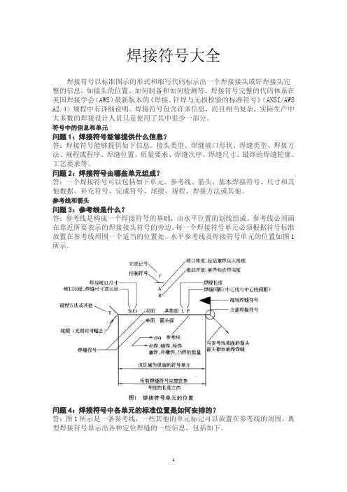
参考线和箭头问题3:参考线是什么?答:参考线是构成一个焊接符号的基础,由水平位置的划线组成。
参考线必须画在靠近所要表示的焊接接头符号的旁边。
每一个焊接符号单元必须根据符号标准放置在参考线周围一个适当的位置处。
水平参考线及焊接符号单元的位置如图1所示。
问题4:焊接符号中各单元的标准位置是如何安排的?答:图1所示是一条参考线,一些其他的单元标记可以放置在参考线的周围。
典型焊接符号显示出各种定位焊缝的一些信息,包括如下。
①尾缀T 只用于特殊的焊缝,例如,焊接方法改变、焊条改变等,可以在图纸上有详细参考说明。
如果没有参考意义或无须规范,尾缀可以省略。
②参考线上的S 记号S取决于焊缝类型,如有坡口焊缝的熔深、填角焊缝的尺寸、塞焊或开槽焊缝的尺寸、点焊或凸焊焊缝的剪切强度等,这个记号一般是位于焊缝符号的左边。
③记号E 在这里代表一个开坡口焊缝的有效尺寸,也称为焊缝尺寸或焊脚高。
有效尺寸的尺度标在圆括号内,无论箭头指向哪里,这个尺寸和坡口总是位于参考线上焊缝符号的左边。
④R 在这里代表形成所需形状的焊缝数之间的空间,对于对接接头来说是敞开的根部。
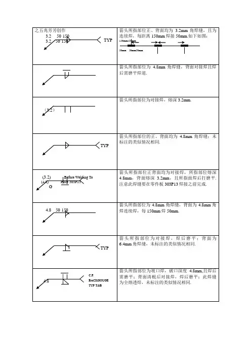
焊接符号大全【2 】焊接符号以标准图示的情势和缩写代码标示出一个焊接接头或钎焊接头完全的信息,如接头的地位.若何制备和若何检测等.焊接符号完全的代码系统在美国焊接学会(AWS)最新版本的《焊接.钎焊与无损磨练的标准符号》(ANSI/AWS A2.4)规程中有具体解释.焊接符号包含很多信息,并且相当庞杂,现实临盆中大多半的焊接设计人员只是应用了个中很少一部分.符号中的信息和单元问题1:焊接符号可以或许供给什么信息?答:焊接符号可以或许供给如下信息.接头类型.焊缝坡口外形.焊缝类型.焊接办法.规程或程序.焊缝地位.质量请求.焊缝次序.焊缝尺寸.最终的焊缝轮廓.工艺请求等.问题2:焊接符号由哪些单元构成?答:一个焊接符号可以包括如下单元.参考线.箭头.根本焊接符号.尺寸和其他数据.补充符号.完成符号.尾缀.规程.焊接办法或其他.参考线和箭头问题3:参考线是什么?答:参考线是构成一个焊接符号的基本,由程度地位的划线构成.参考线必须画在接近所要表示的焊接接头符号的旁边.每一个焊接符号单元必须依据符号标准放置在参考线四周一个恰当的地位处.程度参考线及焊接符号单元的地位如图1所示.问题4:焊接符号中各单元的标准地位是若何安排的?答:图1所示是一条参考线,一些其他的单元标记可以放置在参考线的四周.典范焊接符号显示出各类定位焊缝的一些信息,包括如下.①尾缀T 只用于特别的焊缝,例如,焊接办法转变.焊条转变等,可以在图纸上有具体参考解释.假如没有参考意义或无须规范,尾缀可以省略.②参考线上的S 记号S取决于焊缝类型,若有坡口焊缝的熔深.填角焊缝的尺寸.塞焊或开槽焊缝的尺寸.点焊或凸焊焊缝的剪切强度等,这个记号一般是位于焊缝符号的左边.③记号E 在这里代表一个开坡口焊缝的有效尺寸,也称为焊缝尺寸或焊脚高.有效尺寸的尺度标在圆括号内,无论箭头指向哪里,这个尺寸和坡口老是位于参考线上焊缝符号的左边.④R 在这里代表形成所需外形的焊缝数之间的空间,对于对接接头来说是放开的根部.假如是塞焊或开槽焊缝,R在这里表示填充深度.这个记号位于焊缝符号的中央地位.⑤A 在这里表示对接接头的坡吵嘴度(竖直角),也包括塞焊焊缝的沉入角度.⑥F和A之间的程度短线—在这里代表完成的焊缝外形外形.⑦F 在这里表示获得所需焊缝外形的办法,焊缝外形可以经由过程下述办法获得.打磨(G).机械加工(M).铲削(C).锤击(H).滚轧(R)或者其他(U).⑧L 在这里表示焊缝长度,这个长度标示老是位于焊缝符号的右边.无论箭头位于何处,这个地位老是不变的.⑨P 在这里表示当焊接中止时焊缝的中间线与中间线的间距.⑩(N)在这里代表点焊.缝焊.栓焊.塞焊.开槽焊或凸焊焊缝所请求的数目.问题5:箭头一般放置在哪里?答:箭头线位于参考线的一端或另一端,在焊接接头的箭头线一边有一个箭头,这个箭头能指向任何偏向,向上.向下或向前.向后.一个焊接符号甚至可以有多个箭头.问题6:箭头符号告知人们些什么信息?答:与箭头相干的符号放置在参考线各自接头一边的上面或下面.参考线的术语“箭头侧”是指箭头指向焊缝接头一侧.位于参考线箭头侧的符号是指接头的箭头侧.位于参考线另一侧的符号是指接头的另一侧.当从图纸的底部不雅看时,箭头侧老是更接近不雅看者.箭头侧和另一侧的例子见图2.根本符号问题7:什么是根本的焊接符号?答:根本的焊接符号如图3所示.问题8:已经界说了箭头侧和另一侧,但如何把焊接符号填放在参考线上?答:与焊缝箭头侧和另一侧有关的参考线上.下焊接符号的地位如图4所示.值得留意的是,假如被焊的接头只焊接一面,这种类型的接头只需一个焊接符号即可,放置在与接头施焊侧响应的参考线的一侧.问题9:知道了根本的焊缝符号和箭头的意义,但这些根本符号若何应用呢?答:这些根本符号应用的例子如图5所示.问题11:卷边焊缝符号若何应用?答:与其他焊接符号一样,卷边焊缝符号异常有效.箭头侧的卷边焊缝符号的例子如图7所示.组合焊缝符号问题14:什么是组合焊缝符号?答:一个焊接接头有时往往须要不止一种类型的焊缝.工程构造制作中,带坡口的焊缝常常与另一种焊缝(例如角焊缝)焊接在一路.当消失这种情形时,人们能见到参考线双方都有焊缝符号,如图9所示.问题15:为什么应用多组参考线?若何看懂这些参考线?答:多组参考线表示出焊接操作的次序.第一次焊接操作与箭头一路显示在多组参考线上,在进行下一道线上的操作前,前一次操作必须完成.远离箭头的每一条线都给出每次持续操作的信息,这些操作还包括一些尾缀中不包括的焊接补充信息,例如检测办法等.多组参考线的例子如图10所示.补充符号问题16:什么是补充符号?答:补充符号涉及到焊缝的一些重要信息,是与其他的焊接符号联合在一路的,见图11.问题18:现场焊接符号若何表示?答:现场焊接符号是箭头和参考线联合处的一面小旗.这个小旗表示该焊缝须要在现场进行焊接,而不是在车间中预先焊接好.表示现场焊接的几个焊缝符号如图13所示.问题19:焊接符号如何表示出焊缝熔透程度?答:焊接符号表示的熔透程度是一个背面涂黑的记号(在参考线一边呈半月形).焊缝熔透符号表示在接头一面焊接时另一面的融化状况,这个补充符号还包括(在符号的左边)融化量请求的尺寸.焊缝熔透符号的例子如图14所示.问题21:距离符号表示什么寄义?答:位于参考线上的距离符号,一个方框,表示在接头内放置的材料,称为距离或插片.像背面衬垫材料符号一样,距离符号的特别划定标注在尾缀中,见图16.问题22:材料插入符号表示什么寄义?答:材料插入符号是位于参考线上的一个矩形符号,这个符号表示在焊接接头处插入的填充材料带或环.插片或环在焊接中完全融化,与接头成为整体.可熔插片一般采用钨极氩弧焊进行焊接.这个符号划定放置在带坡口焊缝符号相反的一边.美国焊接学会(AWS)划定将可熔插片分类符号放置在焊接符号的尾缀中.可熔焊接插片符号的例子如图17所示.问题23:焊缝外形符号表示什么寄义?答:外形符号表示对焊缝表面外形的请求.焊缝外形包括腻滑.上凸.下凹.外形符号上的字母表示整修焊缝的办法.C 铲削;G 打磨;H 锤击;M 机械加工;R 滚轧.现实焊缝外形请求的响应符号见图18.问题20:背面垫板符号表示什么寄义?答:矩形垫板符号表示有衬垫材料放置在带坡口焊缝的背面,这个符号除了放置在带坡口焊缝符号的相反一边以外,与塞焊缝符号类似.另一个须要留意的是,字母R可以放置在符号之内,表示焊接之后衬垫材料必须被去除.背面符号划定的衬垫材料可以与母材雷同,也可所以铜.陶瓷.玻璃带.焊剂.气体或其他材料.请求的衬垫材料类型必须在尾缀中注明.背面垫板材料符号的例子如图15所示.问题17:划有圆圈的符号寄义是什么?答:划有圆圈的符号位于衔接参考线和箭头四周的一个圆圈内.这个符号表示某接头四周是持续的焊缝,即使焊接偏向可能产生变化.划有圆圈的焊缝及符号的例子如图12所示.问题13:一个完全的焊缝符号须要哪些最小的单元?答:①参考线+箭头+根本焊接符号.②参考线+箭头+尾缀.二者任选其一.问题12:箭头打折表示什么含意答:箭头打折表示焊接接头两侧只有一边必须开坡口.箭头指向的材料是操作者施焊前应开坡口的一边,如图8所示.问题10:船形地位的V形焊缝符号若何应用?答:单面船形地位的V形焊缝及符号如图6所示.问题24:打底焊道与封底焊道之间有什么差别?答:打底焊道是在厚板单面坡口对接焊时,为了防止角变形或为了防止主动焊时产生烧穿现象,而先在接头背面坡口根部进行的一道焊接.封底焊道是在单面坡口对接焊中,先焊完正面坡口焊缝,在背面铲清焊根后,再进行的一道焊接,目标是保证使焊缝根部完全熔合.问题25:打底焊和封底焊都采用了什么符号?答:这两种焊道采用了雷同的符号,但焊接次序在焊接符号的尾缀中有划定,或者采用组合参考线.打底焊道符号一般标在远离箭头的第一条线上,第二条线上是焊缝坡口符号.打底焊道符号老是标在焊缝坡口符号的另一边.封底焊道符号位于分开箭头的第二条线上,接着是焊缝坡口符号.封底和打底焊道的符号如图19所示.角焊缝尺寸问题26:什么身分决议了角焊缝的尺寸?答:角焊缝尺寸由焊缝尺寸中最短的焊脚高来决议,见图20.问题27:角焊缝的尺寸在焊缝符号上是若何标注的?答:角焊缝尺寸用焊脚高表示,焊脚高尺寸标注在角焊缝符号的旁边,如图21所示.问题28:角焊缝的长度若何肯定?答:角焊缝是一条从一端到另一端持续的焊缝,除非有尺寸限制.假如焊缝不请求是持续的,在角焊缝符号右边应标注一个数码,提醒操作者焊缝的长度,如图22所示.塞焊和开槽焊缝问题29:塞焊焊缝的焊接符号是若何划定的?答:对塞焊焊缝尺寸的划定主如果沉入角度和焊缝填充深度,如图24所示.问题30:开槽焊缝的尺寸若何标注?答:开槽焊缝测量尺寸的依据是开槽的宽度,长条槽是开在被焊工件的接合面上.焊接符号上标有开槽的长度,一般在焊缝符号的右边.问题31:在塞焊焊缝或开槽焊缝的底部能施焊上一层焊道吗?答:可以在塞焊焊缝或开槽焊缝的底部施焊一层焊道,但是这道焊缝现实上是在塞焊或开槽焊缝中的角焊缝,不能被称为塞焊或开槽焊缝.这种情形下形成的焊缝及符号如图25所示.表面焊道问题32:什么是表面焊道?答:表面焊道是指那些堆焊在工件表面以改良抗磨损性.增长表面硬度或具有耐蚀性的金属.为了改良表面硬度或抗磨损性而采用的填充金属称为表面堆焊.这种工艺经常用于推土机刃板.铲斗以及岩石破裂装备上.问题33:表面焊道的尺寸和焊接符号如何表示?答:堆焊焊道的尺寸是从工件表面到焊道面,也即堆焊材料的高度.堆焊焊道尺寸及符号如图26所示.角焊缝尺寸l 问题26:什么身分决议了角焊缝的尺寸?答:角焊缝尺寸由焊缝尺寸中最短的焊脚高来决议,见图20.l 问题27:角焊缝的尺寸在焊缝符号上是若何标注的?答:角焊缝尺寸用焊脚高表示,焊脚高尺寸标注在角焊缝符号的旁边,如图21所示.l 问题28:角焊缝的长度若何肯定?答:角焊缝是一条从一端到另一端持续的焊缝,除非有尺寸限制.假如焊缝不请求是持续的,在角焊缝符号右边应标注一个数码,提醒操作者焊缝的长度,如图22所示.。
资料范本本资料为word版本,可以直接编辑和打印,感谢您的下载焊接符号标注及详细表示方法地点:__________________时间:__________________说明:本资料适用于约定双方经过谈判,协商而共同承认,共同遵守的责任与义务,仅供参考,文档可直接下载或修改,不需要的部分可直接删除,使用时请详细阅读内容焊接符号标注及表示方法—详版什么是焊接符号焊接符号是一种工程语言,能简单、明了地在图纸上说明焊缝的形状、几何尺寸和焊接方法。
我国的焊接符号是由国家标准GB324规定的。
焊接符号有什么作用焊接符号是把在图样上用技术制图方法所表示的焊缝的基本形式和尺寸采用一些符号来表示的方法。
焊接符号可以表示出:(1)所焊焊缝的位置。
(2)焊缝横截面形状(坡口形状)及坡口尺寸。
(3)焊缝表面形状特征。
(4)表示焊缝某些特征或其他要求。
焊缝形式及坡口尺寸在图纸上是怎样表示的焊缝形式及坡口尺寸在图纸上一般采用技术制图的方法表示。
为了简化焊缝在图样上的表示方法,现采用国家标准规定的焊缝符号及坡口尺寸的表示方法。
焊接符号由哪几部分组成焊接符号一般是由基本符号和指引线组成,必要时还可以加上辅助符号、补充符号和焊缝尺寸符号。
焊缝形式及坡口尺寸在图纸上是怎样表示的焊缝形式及坡口尺寸在图纸上一般采用技术制图的方法表示。
为了简化焊缝在图样上的表示方法,现采用国家标准规定的焊缝符号及坡口尺寸的表示方法。
表示焊缝的基本符号有哪些焊缝基本符号是表示焊缝截面形状的符号,它采用近似于焊缝横剖面形状的符号来表示。
GB324-1988中规定了13种焊缝形式的符号,见表2-2。
点击下载 HYPERLINK "/zt-hanjiefuhao/%E7%84%8A%E6%8E%A5%E7%AC%A6%E5%8F%B7%E8%AF%B4%E6%98%8E%E5 %A4%A7%E5%85%A8.xls" 焊接符号说明大全(excel表格详细讲解)焊接加工符号的国家标准有哪些焊接符号的国家标准主要有两个:(1) HYPERLINK"/biaozhun/showbz_915.html" \t "_blank" GB324一2008《焊缝代号》。
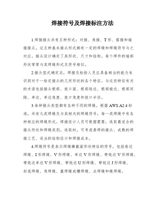
焊接符号及焊接标注方法1.焊接接头共有五种形式:对接、角接、T形、搭接和端接接头。
这五种基本接头形式都有一定的焊缝和焊缝符号与之对应。
接头设计确定了其形状、尺寸和结构。
每个焊件的端部形状常常与其焊缝形式及符号相似。
2.接头型式确定后,焊接及检验人员应具备相当的能力来识别对于一给定接头的几何形状的各个特征。
与这些特征有关的术语包括接头根部、坡口面、根部钝边、根部棱边、根部间隙、单边、单边角度、坡口角度和坡口半径。
3.每种接头类型都有各种不同的焊缝。
根据AWS A2.4标准,共有九类焊缝及与其相关的焊缝符号,每一类焊缝中有各种相应的焊缝形式。
焊接设计人员可根据需要,选取最适合的接头形状和焊缝类别。
选取时,可考虑易焊的接头、成熟的焊接工艺、适当的结构设计和焊接成本。
4.焊缝符号是表示焊缝横截面形状特征的符号,包括卷边焊缝、I形焊缝、V形焊缝、单边V形焊缝、带钝边V形焊缝、带钝边单边V形焊缝、带钝边U形焊缝、带钝边J形焊缝、封底焊缝、角焊缝、塞焊缝或槽焊缝、点焊缝和缝焊缝。
5.焊缝的辅助符号是表示焊缝表面形状特征的符号,包括平面符号、凹面符号和凸面符号。
焊缝的辅助符号的应用见表3.XXX n of welds。
as shown in Table 4.are used to XXX size symbols。
as shown in Table 5.may be added to basic symbols when XXX in Table mon metal welding method codes are listed in Table 7.Examples of XXX 9.Table 4: Supplementary symbols for weldsNumber1NameBacking strip symbol①Symbol nXXX at the bottom of the weld2Three-sided XXX3XXXIndicates that there is a weld on three sidesIndicates that there is a weld around the workpiece45On-site symbolTail symbolXXX on site or at the n site。
2023年度焊接符号大全由于焊接是现代制造业中的重要工艺之一,因此焊接符号也成为大众关注的焦点。
为了帮助大家更好的了解焊接符号,本文将介绍2023年度焊接符号大全。
一、焊条符号1. AWS(美国焊接学会)E7018:表示一种炭钢电焊条,适用于直流电焊和交流电焊。
2. AWS E6013:表示一种碱性电焊条,可用于炭钢的所有硬度等级的焊接。
3. AWS E308L:表示一种不锈钢电焊条,适用于焊接304L和308L不锈钢材料。
4. AWS E316L:表示一种镍铬钼不锈钢电焊条,适用于焊接316和316L不锈钢材料。
二、焊接缝符号1. V型翻边焊接缝(V-groove):这种缝口形状呈V字形,适用于厚度超过6毫米的材料。
2. X型焊缝(X-groove):这种缝口形状为双面斜角,适用于厚度为8毫米以上的材料。
3. W型焊缝(W-groove):这种缝口形状为双面倒角,适用于搭接板材厚度为15毫米以上的材料。
4. U型焊缝(U-groove):这种缝口形状呈U字形,适用于厚度大于12毫米的板材和管道的连接。
三、焊接位置符号1. 1G:表示水平位置下的焊接;2. 2G:表示向上仰视时的竖直位置下的焊接;3. 3G:表示向前仰视时的竖直位置下的焊接;4. 4G:表示在向下仰视时的竖直位置下的焊接。
四、焊缝表面处理符号1. V:表示在焊接之前,要用钢刷对工件的缝口进行清洁;2. F:表示在焊接之前,先要将缝口表面打磨干净;3. G:表示在缝口中性气体焊接时,需要使用惰性气体将焊接处覆盖起来。
五、焊接质量等级符号总共有三个等级:1. A级:表示最高等级,适用于关键的焊接结构;2. B级:表示适用于普通的焊接结构,但质量仍需保证;3. C级:表示适用于非常规的焊接结构,例如对于未知材料的焊接。
以上就是2023年度的焊接符号大全,希望这篇文章能够帮助你更好地了解焊接符号。
当然,由于焊接符号会根据不同地区和不同产业有所差异,因此这份符号大全仅供参考。
aws焊接符号标准AWS焊接符号标准。
AWS(American Welding Society)焊接符号标准是指在焊接工程中,为了统一和规范符号的使用,AWS制定了一系列的标准符号,用于表示焊接过程中的各种信息,包括焊接方法、焊缝形状、焊接材料等。
这些符号的准确使用对于焊接工程的质量和安全至关重要。
本文将介绍AWS焊接符号标准的相关内容,以便大家更好地理解和运用这些符号。
首先,我们来看一下AWS焊接符号标准中的常用符号。
在焊接图纸或工程文件中,常见的符号包括焊缝形状符号、焊接方法符号、焊接位置符号、焊接材料符号等。
这些符号的使用可以帮助工程师和焊工准确地理解焊接要求,从而保证焊接质量。
焊缝形状符号是指用于表示焊缝形状的符号,常见的有V型、X型、U型等。
这些符号可以告诉焊工需要将焊缝切割成何种形状,以满足工程要求。
焊接方法符号则用于表示所采用的焊接方法,比如手工电弧焊、气体保护焊等。
这些符号的正确使用可以确保焊接过程中采用了正确的焊接方法,从而保证焊接质量。
除了上述常见的符号外,AWS焊接符号标准还包括了一些特殊符号,比如表示焊接位置的符号、表示焊接材料的符号等。
这些符号在特定的焊接工程中可能会被用到,因此了解这些符号的含义和用法对于工程师和焊工来说是非常重要的。
在实际的焊接工程中,正确使用AWS焊接符号标准可以带来诸多好处。
首先,它可以减少沟通误解,确保所有相关人员对焊接要求有一个统一的理解。
其次,它可以提高工作效率,因为焊工可以根据符号直接进行操作,而不需要再花时间去解释焊接要求。
最重要的是,它可以保证焊接质量,因为符号的准确使用可以确保焊接过程中的每一个细节都符合工程要求。
总的来说,AWS焊接符号标准是焊接工程中不可或缺的一部分。
正确理解和运用这些符号对于保证焊接质量和安全至关重要。
希望本文能够帮助大家更好地理解和运用AWS焊接符号标准,从而为焊接工程的顺利进行贡献自己的力量。

焊接符号大全焊接符号以标准图示的形式和缩写代码标示出一个焊接接头或钎焊接头完整的信息,如接头的位置、如何制备和如何检测等。
焊接符号完整的代码体系在美国焊接学会(AWS)最新版本的《焊接、钎焊与无损检验的标准符号》(ANSI/AWS A2.4)规程中有详细说明。
焊接符号包含许多信息,而且相当复杂,实际生产中大多数的焊接设计人员只是使用了其中很少一部分。
符号中的信息和单元问题1:焊接符号能够提供什么信息?答:焊接符号能够提供如下信息。
接头类型、焊缝坡口形状、焊缝类型、焊接方法、规程或程序、焊缝位置、质量要求、焊缝次序、焊缝尺寸、最终的焊缝轮廓、工艺要求等。
问题2:焊接符号由哪些单元组成?答:一个焊接符号可以包括如下单元。
参考线、箭头、基本焊接符号、尺寸和其他数据、补充符号、完成符号、尾缀、规程、焊接方法或其他。
参考线和箭头问题3:参考线是什么?答:参考线是构成一个焊接符号的基础,由水平位置的划线组成。
参考线必须画在靠近所要表示的焊接接头符号的旁边。
每一个焊接符号单元必须根据符号标准放置在参考线周围一个适当的位置处。
水平参考线及焊接符号单元的位置如图1所示。
问题4:焊接符号中各单元的标准位置是如何安排的?答:图1所示是一条参考线,一些其他的单元标记可以放置在参考线的周围。
典型焊接符号显示出各种定位焊缝的一些信息,包括如下。
①尾缀T 只用于特殊的焊缝,例如,焊接方法改变、焊条改变等,可以在图纸上有详细参考说明。
如果没有参考意义或无须规范,尾缀可以省略。
②参考线上的S 记号S取决于焊缝类型,如有坡口焊缝的熔深、填角焊缝的尺寸、塞焊或开槽焊缝的尺寸、点焊或凸焊焊缝的剪切强度等,这个记号一般是位于焊缝符号的左边。
③记号E 在这里代表一个开坡口焊缝的有效尺寸,也称为焊缝尺寸或焊脚高。
有效尺寸的尺度标在圆括号内,无论箭头指向哪里,这个尺寸和坡口总是位于参考线上焊缝符号的左边。
④R 在这里代表形成所需形状的焊缝数之间的空间,对于对接接头来说是敞开的根部。
AS澳大利亚标准焊接符号在图纸上表示方法AS 1101.3 – 2005澳大利亚标准TM一般工程图形符号第3部分:焊接和无损探伤本澳大利亚标准是由委员会WD-001,焊接定义和符号,制定的。
它是2004年11月25日以澳大利亚标准委员会的名义批准的。
本标准发表于2005年3月31日。
以下机构参加了委员会WD-001:澳大利亚工业集团澳大利亚钢铁制造商委员会新西兰大型工程研究协会澳大利亚焊接技术研究所不断更新标准标准系指现有反映科技和体制进步的文件。
为使标准持续有效,应定期审查所有标准,并发行新版本标准。
标准各版发行过程中,可做出相关修订,也可撤销标准。
重要的是,读者应确保自己使用的是现行标准,其中应包括自从标准购买之以来已发行的所有标准修订内容。
欲了解澳大利亚和新西兰联合标准的详细资料,请访问标准澳大利亚公司网站.au 或新西兰标准公司网站,通过在线目录查找相关标准。
此外还可通过出版物目录,获取每年1月1日的最新信息,月报“澳大利亚标准”中包含各月发行版本和修订内容的完整清单。
根据与SAI Global 的合同发表和发放澳大利亚标准协会提供的澳大利亚标准TM和其他产品及服务, SAI Global经营“标准网上商店”。
到校我们欢迎读者对标准改进提出任何意见,如发现任何明显错误或含糊不清的地方,希望立即通知我们。
读者可通过发送邮件至mail@.au或写信寄至GPO Box 5420,悉尼,NSW 2001澳大利亚国际标准公司董事长(收),与我们联系。
为了征求意见,本标准曾经利用编号DR 04480以草案的形式发表。
AS 1101.3 – 2005澳大利亚标准TM一般工程图形符号第3部分:焊接和无损探伤首次发表用名AS Z6 – 1955前一版AS 1101.3 – 1987第三版2005版权© 澳大利亚标准保留所有权利。
未经出版人书面允许,不得以任何形式或者任何手段,电子的或者机械的,包括影印,复制或者拷贝本文件的任何部分。
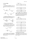
6.Groove Welds6.1 General6.1.1 Single-Groove Dimensions. Groove welddimensions shall be specified on the same side of thereference line as the weld symbol [see Figure 12(A) and(F)].6.1.2 Double-Groove Dimensions. Each groove of adouble-groove joint shall be dimensioned; however, theroot opening need appear only once (see Figure 13).6.1.3 Broken Arrow and the Straight Arrow6.1.3.1 Broken Arrow. A broken arrow is used,when necessary, to specify which member is to have abevel- or J-groove edge shape for single- or double-beveland single- or double-J-groove welds (see 5.4.1).6.1.3.2 Straight Arrow for Single-GrooveWelds. A straight arrow is used when either membermay have the desired edge shape for single-bevel- orsingle-J-groove welds.6.1.3.3 Straight Arrow for Double-GrooveWelds. A straight arrow is used when either or bothmembers may have the desired edge shape for double-bevel- or double-J-groove welds. The edge shape may bein one member on the arrow side of the joint and in thesecond member on the other side of the joint.6.2 Depth of Bevel and Groove Weld Size6.2.1 Location. When used, the depth of bevel, “S,”and groove weld size, “(E),” shall be placed to the left ofthe weld symbol [see Figure 12(A), (B), (C), and (F) andFigures 13 through 15].--`,,```,,,,````-`-`,,`,,`,`,,`-----`,,```,,,,````-`-`,,`,,`,`,,`-----`,,```,,,,````-`-`,,`,,`,`,,`-----`,,```,,,,````-`-`,,`,,`,`,,`---6.2.2 Complete Joint Penetration. Omitting thedepth of bevel and groove weld size dimensions from thewelding symbol requires a groove weld that extendsthrough the thickness of the joint [see Figure 12(D) and(E), Figures 18 and 19, as well as Annex D6.2.2].6.2.3 Partial Joint Penetration Welds, GrooveWeld Size Specified, Depth of Bevel Not Specified.The size of groove welds that extend only partly throughthe joint shall be specified in parentheses on the weldingsymbol [see Figure 12(A), (C), and (F)].6.2.4Complete Joint Penetration Double-GrooveWelds, Weld Size Specified, Depth of Bevel Not Spec-ified. The size of nonsymmetrical groove welds (arrowside versus other side) that extend completely throughthe joint shall be specified in parentheses on the weldingsymbol [see Figure 16(B) and (C)].The size of symmetrical groove welds (arrow side versusother side) that extend completely through the joint maybe specified in parentheses on the welding symbol [seeFigure 16(A)].6.2.5 Depth of Bevel Specified, Groove Weld SizeSpecified Elsewhere. A dimension not in parenthesesplaced to the left of a bevel-, V-, J-, or U-groove weldsymbol specifies the depth of bevel only.6.2.6 Depth of Bevel and Groove Weld Size Speci-fied. The depth of bevel, “S,” and groove weld size,“(E),” are located to the left of the weld symbol as“S(E).” For square groove welds, only the groove weldsize, “(E),” is shown (see Figures 14 and 17). --`,,```,,,,````-`-`,,`,,`,`,,`-----`,,```,,,,````-`-`,,`,,`,`,,`-----`,,```,,,,````-`-`,,`,,`,`,,`---6.2.7 Depth of Bevel Specified, Groove Weld SizeNot Specified. A welding symbol with a depth of bevelspecified, and the groove weld size not included and notspecified elsewhere, may be used to specify a grooveweld size not less than the depth of bevel.6.2.8 Joint Geometry Not Specified, CompleteJoint Penetration Required. Optional joint geometrywith complete joint penetration (CJP) required is speci-fied by placing the letters “CJP” in the tail of the weldingsymbol and omitting the weld symbol (see Figure 20).6.2.9 Joint Geometry Not Specified, Groove WeldSize Specified. For optional joint geometry, the grooveweld size is specified by placing dimension “(E)” on thearrow side or the other side of the reference line asrequired, but omitting the weld symbol (see Figure 21).6.2.10 Flare Groove Welds. Dimension “S” of flare-groove welds is considered as extending only to thetangent point indicated below by dimension lines (seeFigure 22(B) and (C) and Annex D6.2.10).6.3 Groove Dimensions6.3.1 Root Opening. The root opening of groovewelds shall be specified inside the weld symbol and onlyon one side of the reference line (see Figure 18).6.3.2 Groove Angle. The groove angle of groovewelds shall be specified outside the weld symbol (seeFigure 19).--`,,```,,,,````-`-`,,`,,`,`,,`-----`,,```,,,,````-`-`,,`,,`,`,,`---33--`,,```,,,,````-`-`,,`,,`,`,,`---34--`,,```,,,,````-`-`,,`,,`,`,,`-----`,,```,,,,````-`-`,,`,,`,`,,`-----`,,```,,,,````-`-`,,`,,`,`,,`---6.3.3 Radii and Root Faces. The groove radii and theroot faces of U- and J-groove welds shall be specified bya cross section, detail, or other data with referencethereto in the tail of the welding symbol (see 5.11).6.4 Length of Groove Welds6.4.1 Location. The length of a groove weld, whenindicated on the welding symbol, shall be specified to theright of the weld symbol [see Figure 23(A) and (C)].6.4.1.1 Full Length. When a groove weld is toextend for the full length of the joint, no length dimen-sion need be specified on the welding symbol [see Figure23(B)].6.4.1.2 Specific Lengths. Specific lengths ofgroove welds and their locations may be specified bysymbols in conjunction with dimension lines [see Figure23(C)].6.4.1.3 Hatching. Hatching may be used to graphi-cally depict groove welds.6.4.2 Changes in the Direction of Welding. Symbolsfor groove welds involving changes in direction of weld-ing shall be in accordance with 5.9.2 (see Figure 24).6.5 Intermittent Groove Welds6.5.1 Pitch. The pitch of intermittent groove weldsshall be the distance between the centers of adjacentweld segments on one side of the joint [see Figure25(A)].6.5.2 Pitch Dimension Location. The pitch of inter-mittent groove welds shall be specified to the right of thelength dimension following a hyphen [see Figure 25(A)].6.5.3 Chain Intermittent Groove Welds. Dimen-sions of chain intermittent groove welds shall be speci-fied on both sides of the reference line. The segments ofchain intermittent groove welds are approximately oppo-site one another across the joint [see Figure 25(B)].6.5.4 Staggered Intermittent Groove Welds.Dimensions of staggered intermittent groove welds shallbe specified on both sides of the reference line, and thegroove weld symbols shall be offset on opposite sides ofthe reference line as shown below. The segments of stag-gered intermittent groove welds shall be symmetricallyspaced on both sides of the joint as shown in Figure25(C).--`,,```,,,,````-`-`,,`,,`,`,,`-----`,,```,,,,````-`-`,,`,,`,`,,`---AWS A2.4:20076.5.5 Extent of Welding. In the case of intermittentgroove welds, additional weld lengths that are intendedat the ends of the joint shall be specified by separatewelding symbols and dimensioned on the drawing [seeFigure 25(D)]. When no weld lengths are intended at theends of the joint, the unwelded lengths should not exceedthe clear distance between weld segments and should beso dimensioned on the drawing [see Figure 25(E)].6.5.6 Location of Intermittent Welds. When thelocation of intermittent welds is not obvious, such as on acircular weld joint, it will be necessary to provide spe-cific segment locations by using dimension lines (see6.4.1.2 and7.3.1.2) or hatching (see 6.4.1.3 and 7.3.1.3).6.6 Contours and Finishing of Groove Welds6.6.1 Contours Obtained by Welding. Groove weldsthat are to be welded with approximately flush or convexfaces without postweld finishing shall be specified byadding the flush or convex contour symbol to the weld-ing symbol [see 5.12 and Figure 26(A)].6.6.2 Contours Obtained by Postweld Finishing.Groove welds whose faces are to be finished flush orconvex by postweld finishing shall be specified byadding both the appropriate contour symbol and finish-ing designator to the welding symbol. Welds that requirea flat but not flush surface, require an explanatory note inthe tail of the welding symbol [see 5.12.2 and Figure26(B) and (C)].6.7 Back and Backing Welds6.7.1 General. The back and backing weld symbolsare identical. The sequence of welding determines whichdesignation applies. The back weld is made after thegroove weld, and the backing weld is made before thegroove weld (see 6.7.2 and 6.7.3).6.7.2 Back Weld Symbol. The back weld symbol isplaced on the side of the reference line opposite a grooveweld symbol. When a single reference line is used, “backweld” shall be specified in the tail of the welding sym-bol. Alternately, if multiple reference lines are used, theback weld symbol shall be placed on a reference linesubsequent to the reference line specifying the grooveweld [see Figure 27(A)].6.7.3 Backing Weld Symbol. The backing weld sym-bol is placed on the side of the reference line opposite agroove weld symbol. When a single reference line isused, “backing weld” shall be specified in the tail of thewelding symbol. Alternately, if multiple reference linesare used, the backing weld symbol shall be placed on areference line prior to the reference line specifying thegroove weld [see Figure 27(B) and (C)].AWS A2.4:2007--`,,```,,,,````-`-`,,`,,`,`,,`---AWS A2.4:2007 --`,,```,,,,````-`-`,,`,,`,`,,`---AWS A2.4:20076.7.4 Contour and Finishing of Back or BackingWelds6.7.4.1 Contours Obtained by Welding. Back orbacking welds that are to be welded with approximatelyflush or convex faces without postweld finishing shall bespecified by adding the flush or convex contour symbolto the welding symbol (see 5.12).6.7.4.2 Contours Obtained by Postweld Finish-ing. Back or backing welds that are to be finishedapproximately flush or convex by postweld finishingshall be specified by adding the appropriate contour sym-bol and finishing designator to the welding symbol (see5.12.2 and 5.12.3). Welds that require a flat but not flushsurface require an explanatory note in the tail of the weld-ing symbol.6.8 Joints with Backing. A joint with backing is speci-fied by placing the backing symbol on the side of thereference line opposite the groove weld symbol. If thebacking is to be removed after welding, an “R” shallbe placed in the backing symbol [see Figure 28(A)].The material and the dimensions of the backing shall bespecified in the tail of the welding symbol or on thedrawing.6.9 Joints with Spacers. A joint with a required spaceris specified with the groove weld symbol modified toshow a rectangle within it [see Figure 28(B)]. In case ofmultiple reference lines, the rectangle shall appear on thereference line nearest to the arrow [see Figure 28(C)].The material and the dimensions of the spacer shall be spec-ified in the tail of the welding symbol or on the drawing. --`,,```,,,,````-`-`,,`,,`,`,,`---AWS A2.4:20076.10 Consumable Inserts. Consumable inserts shall be specified by placing the consumable insert symbol on the side of the reference line opposite the groove weld sym-bol (see Figure 29). The AWS consumable insert class shall be placed in the tail of the welding symbol (for the AWS insert classes, see AWS A5.30/A5.30M, Specifica-tion for Consumable Inserts ).6.11 Groove Welds with Backgouging. Along with other joint details, the welding symbol shall include a reference to backgouging in the tail. In the case of non-symmetrical double-groove welds, the symbol shall show the required depth of groove for each side of the joint [see Figure 30(A)], together with the requiredgroove angles. In the case of single-groove welds with-out a root face or symmetrical double-groove welds without a root face, the welding symbol need not include the depth of groove dimension [see 6.2.2 and Figure 30(B) and (C)].6.12 Seal Welds. When the intent of the weld is to fulfil a sealing function only, the weld shall be specified in the tail of the welding symbol as a seal weld (see Annex D6.12).6.13 Skewed Joints. When the angle between the fusion faces is such that the identification of the weld type and,hence, proper weld symbol is in question, the detail of the desired joint and weld configuration shall be shown on the drawing with all necessary dimensions (see Figure 31).--`,,```,,,,````-`-`,,`,,`,`,,`---AWS A2.4:2007--`,,```,,,,````-`-`,,`,,`,`,,`---AWS A2.4:2007AWS A2.4:2007--`,,```,,,,````-`-`,,`,,`,`,,`---AWS A2.4:2007--`,,```,,,,````-`-`,,`,,`,`,,`---AWS A2.4:20077.Fillet Welds7.1 General7.1.1 Dimension Location. The dimensions of filletwelds shall be shown on the same side of the referenceline as the weld symbol (see Figures 32 through 34).7.1.2 Double Fillet Welds. The dimensions of filletwelds on both sides of a joint shall be specified whetherthe dimensions are identical or different [see Figure 32(B)and (C) and Figure 34(B) and (C)].7.1.3 Drawing Notes. Dimensions of fillet welds cov-ered by drawing notes need not be repeated on the weld-ing symbols in accordance with 5.11.6.7.2 Size of Fillet Welds7.2.1 Location. The fillet weld size, “S,” shall bespecified to the left of the weld symbol [see Figure 32(A),(B), (C), and (D)].7.2.2 Unequal Legs. The size of a fillet weld, “S,”with unequal legs shall be specified to the left of the weldsymbol as shown below. Weld orientation is not speci-fied by the symbol and shall be shown on the drawing toensure clarity [see Figure 32(D)].7.3 Length of Fillet Welds7.3.1 Location. The length of a fillet weld, when indi-cated on the welding symbol, shall be specified to theright of the weld symbol [see Figure 32(F)].7.3.1.1 Full Length. When a fillet weld extendsfor the full length of the joint, no length dimension needbe specified on the welding symbol [see Figure 32(A),(B), (C), (D), and (E)].7.3.1.2 Specific Lengths. Specific lengths of filletwelds, and their location, may be specified by symbolsin conjunction with dimension lines [see Figures 8(C) and32(F)].7.3.1.3 Hatching. Hatching may be used to graphi-cally depict fillet welds (see 6.4.1.3).--`,,```,,,,````-`-`,,`,,`,`,,`---7.3.2 Changes in Direction of Welding. Symbols forfillet welds involving changes in the direction of weldingshall be in accordance with 5.9.2 [see Figure 9(A)].7.4 Intermittent Fillet Welds7.4.1 Pitch. The pitch of intermittent fillet welds shallbe the distance between the centers of adjacent weld seg-ments on one side of the joint [see Figure 33(A)].7.4.2 Pitch Dimension Location. The pitch of inter-mittent fillet welds shall be specified to the right of thelength dimension following a hyphen (see Figure 33).7.4.3 Chain Intermittent Fillet Welds. Dimensionsof chain intermittent fillet welds shall be specified onboth sides of the reference line. The segments of chainintermittent fillet welds shall be opposite one anotheracross the joint [see Figure 33(B)].7.4.4 Staggered Intermittent Fillet Welds. Thedimensions of staggered intermittent fillet welds shall bespecified on both sides of the reference line, and the filletweld symbols shall be offset on opposite sides of the ref-erence line as shown below. The segments of staggeredintermittent fillet welds shall be symmetrically spaced onboth sides of the joint as shown in Figure 33(C).7.4.5 Extent of Welding. In the case of intermittentfillet welds, additional weld lengths that are intended atthe ends of the joint shall be specified by separate weld-ing symbols and dimensioned on the drawing [see Figure33(D)]. When no weld lengths are intended at the ends ofthe joint, the unwelded lengths should not exceed theclear distance between weld segments and be so dimen-sioned on the drawing [see Figure 33(E)].7.4.6 Location of Intermittent Welds. When thelocation of intermittent welds is not obvious, such as on acircular weld joint, it will be necessary to provide spe-cific segment locations by dimension lines (see 6.4.1.2and 7.3.1.2) or by hatching (see 6.4.1.3 and 7.3.1.3).7.5 Fillet Welds in Holes and Slots. Fillet welds inholes and slots shall be specified by the use of fillet weldsymbols [see Figure 34(A)].7.6 Contours and Finishing of Fillet Welds7.6.1 Contours Obtained by Welding. Fillet weldsthat are to be welded with approximately flat, convex, orconcave faces without postweld finishing shall be speci-fied by adding the flat, convex, or concave contour sym-bol to the welding symbol (see 5.12.1).7.6.2 Contours Obtained by Postweld Finishing.Fillet welds that are to be finished approximately flat,convex, or concave by postweld finishing shall be speci-fied by adding both the appropriate contour symbol andfinishing designator to the welding symbol (see 5.12.2).7.7 Skewed Joints. When the angle between the fusionfaces is such that the identification of the weld type andthus the proper weld symbol may be in question, thedetail of the desired joint and weld configuration shall beshown on the drawing (see 6.13 and Figure 31).--`,,```,,,,````-`-`,,`,,`,`,,`-----`,,```,,,,````-`-`,,`,,`,`,,`---。
焊接符号标注及表示方法焊接符号什么是焊接符号焊接符号是一种工程语言,能简单、明了地在图纸上说明焊缝的形状、几何尺寸和焊接方法。
我国的焊接符号是由国家标准GB324规定的。
焊接符号有什么作用焊接符号是把在图样上用技术制图方法所表示的焊缝的基本形式和尺寸采用一些符号来表示的方法。
焊接符号可以表示出:(1)所焊焊缝的位置。
(2)焊缝横截面形状(坡口形状)及坡口尺寸。
(3)焊缝表面形状特征。
(4)表示焊缝某些特征或其他要求。
焊缝形式及坡口尺寸在图纸上是怎样表示的焊缝形式及坡口尺寸在图纸上一般采用技术制图的方法表示。
为了简化焊缝在图样上的表示方法,现采用国家标准规定的焊缝符号及坡口尺寸的表示方法。
焊接符号由哪几部分组成焊接符号一般是由基本符号和指引线组成,必要时还可以加上辅助符号、补充符号和焊缝尺寸符号。
焊缝形式及坡口尺寸在图纸上是怎样表示的焊缝形式及坡口尺寸在图纸上一般采用技术制图的方法表示。
为了简化焊缝在图样上的表示方法,现采用国家标准规定的焊缝符号及坡口尺寸的表示方法。
表示焊缝的基本符号有哪些焊缝基本符号是表示焊缝截面形状的符号,它采用近似于焊缝横剖面形状的符号来表示。
GB324-1988中规定了13种焊缝形式的符号,见表2-2。
点击下载焊接符号说明大全(excel表格详细讲解)焊接加工符号的国家标准有哪些焊接符号的国家标准主要有两个:(1) GB324一2008《焊缝代号》。
(2) GB985-1988《手工电弧焊焊接接头的基本形式与尺寸》。
表示焊缝的辅助符号有哪些辅助符号表示焊缝表面形状特征的符号,见表2-3。
不需要确切地说明焊缝的表面形状时,可以不用辅助符号。
表示焊缝的补充符号有哪些补充符号是为了补充说明焊缝的某些特征而采用的符号,见表2-4。
表示焊缝的尺寸符号有哪些焊缝的尺寸符号见表2-5。
焊接符号标注中的指引线指引线是表示指引焊缝位置的符号。
由带箭头的指引线和两条基准线(一条为实线,另一条为虚线)组成。
焊接符号大全32167[方案]焊接符号大全焊接符号以标准图示的形式和缩写代码标示出一个焊接接头或钎焊接头完整的信息,如接头的位置、如何制备和如何检测等。
焊接符号完整的代码体系在美国焊接学会(AWS)最新版本的《焊接、钎焊与无损检验的标准符号》(ANSI/AWS A2.4)规程中有详细说明。
焊接符号包含许多信息,而且相当复杂,实际生产中大多数的焊接设计人员只是使用了其中很少一部分。
符号中的信息和单元问题1:焊接符号能够提供什么信息,答:焊接符号能够提供如下信息。
接头类型、焊缝坡口形状、焊缝类型、焊接方法、规程或程序、焊缝位置、质量要求、焊缝次序、焊缝尺寸、最终的焊缝轮廓、工艺要求等。
问题2:焊接符号由哪些单元组成,答:一个焊接符号可以包括如下单元。
参考线、箭头、基本焊接符号、尺寸和其他数据、补充符号、完成符号、尾缀、规程、焊接方法或其他。
参考线和箭头问题3:参考线是什么,答:参考线是构成一个焊接符号的基础,由水平位置的划线组成。
参考线必须画在靠近所要表示的焊接接头符号的旁边。
每一个焊接符号单元必须根据符号标准放置在参考线周围一个适当的位置处。
水平参考线及焊接符号单元的位置如图1所示。
问题4:焊接符号中各单元的标准位置是如何安排的, 答:图1所示是一条参考线,一些其他的单元标记可以放置在参考线的周围。
典型焊接符号显示出各种定位焊缝的一些信息,包括如下。
?尾缀T 只用于特殊的焊缝,例如,焊接方法改变、焊条改变等,可以在图纸上有详细参考说明。
如果没有参考意义或无须规范,尾缀可以省略。
?参考线上的S 记号S取决于焊缝类型,如有坡口焊缝的熔深、填角焊缝的尺寸、塞焊或开槽焊缝的尺寸、点焊或凸焊焊缝的剪切强度等,这个记号一般是位于焊缝符号的左边。
?记号E 在这里代表一个开坡口焊缝的有效尺寸,也称为焊缝尺寸或焊脚高。
有效尺寸的尺度标在圆括号内,无论箭头指向哪里,这个尺寸和坡口总是位于参考线上焊缝符号的左边。
?R在这里代表形成所需形状的焊缝数之间的空间,对于对接接头来说是敞开的根部。
焊接符号⼤全(详解)焊接符号⼤全焊接符号以标准图⽰的形式和缩写代码标⽰出⼀个焊接接头或钎焊接头完整的信息,如接头的位置、如何制备和如何检测等。
焊接符号完整的代码体系在美国焊接学会(AWS)最新版本的《焊接、钎焊与⽆损检验的标准符号》(ANSI/AWS A2.4)规程中有详细说明。
焊接符号包含许多信息,⽽且相当复杂,实际⽣产中⼤多数的焊接设计⼈员只是使⽤了其中很少⼀部分。
符号中的信息和单元问题1:焊接符号能够提供什么信息?答:焊接符号能够提供如下信息。
接头类型、焊缝坡⼝形状、焊缝类型、焊接⽅法、规程或程序、焊缝位置、质量要求、焊缝次序、焊缝尺⼨、最终的焊缝轮廓、⼯艺要求等。
问题2:焊接符号由哪些单元组成?答:⼀个焊接符号可以包括如下单元。
参考线、箭头、基本焊接符号、尺⼨和其他数据、补充符号、完成符号、尾缀、规程、焊接⽅法或其他。
参考线和箭头问题3:参考线是什么?答:参考线是构成⼀个焊接符号的基础,由⽔平位置的划线组成。
参考线必须画在靠近所要表⽰的焊接接头符号的旁边。
每⼀个焊接符号单元必须根据符号标准放置在参考线周围⼀个适当的位置处。
⽔平参考线及焊接符号单元的位置如图1所⽰。
问题4:焊接符号中各单元的标准位置是如何安排的?答:图1所⽰是⼀条参考线,⼀些其他的单元标记可以放置在参考线的周围。
典型焊接符号显⽰出各种定位焊缝的⼀些信息,包括如下。
①尾缀T 只⽤于特殊的焊缝,例如,焊接⽅法改变、焊条改变等,可以在图纸上有详细参考说明。
如果没有参考意义或⽆须规范,尾缀可以省略。
②参考线上的S 记号S取决于焊缝类型,如有坡⼝焊缝的熔深、填⾓焊缝的尺⼨、塞焊或开槽焊缝的尺⼨、点焊或凸焊焊缝的剪切强度等,这个记号⼀般是位于焊缝符号的左边。
③记号E 在这⾥代表⼀个开坡⼝焊缝的有效尺⼨,也称为焊缝尺⼨或焊脚⾼。
有效尺⼨的尺度标在圆括号内,⽆论箭头指向哪⾥,这个尺⼨和坡⼝总是位于参考线上焊缝符号的左边。
④R 在这⾥代表形成所需形状的焊缝数之间的空间,对于对接接头来说是敞开的根部。