CA simulation on DRX
- 格式:pdf
- 大小:2.19 MB
- 文档页数:19
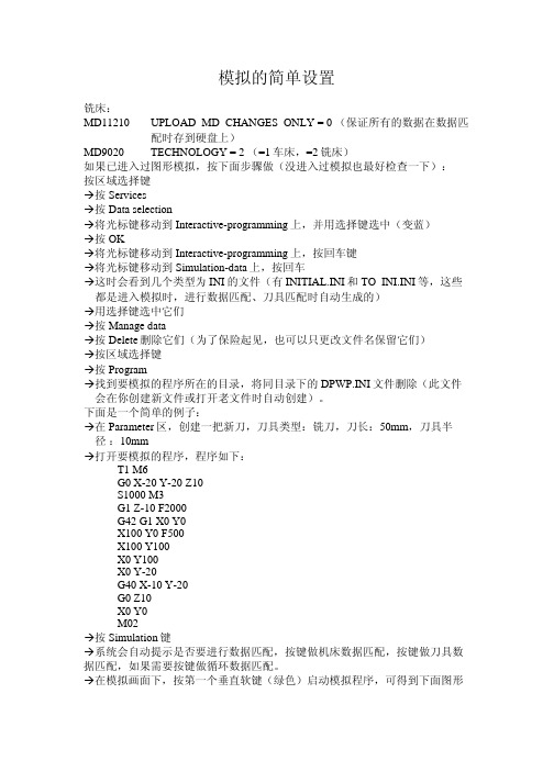
模拟的简单设置铣床:MD11210 UPLOAD_MD_CHANGES_ONLY = 0 (保证所有的数据在数据匹配时存到硬盘上)MD9020 TECHNOLOGY = 2 (=1车床,=2铣床)如果已进入过图形模拟,按下面步骤做(没进入过模拟也最好检查一下):按区域选择键Æ按ServicesÆ按Data selectionÆ将光标键移动到Interactive-programming上,并用选择键选中(变蓝)Æ按OKÆ将光标键移动到Interactive-programming上,按回车键Æ将光标键移动到Simulation-data上,按回车Æ这时会看到几个类型为INI的文件(有INITIAL.INI和TO_INI.INI等,这些都是进入模拟时,进行数据匹配、刀具匹配时自动生成的)Æ用选择键选中它们Æ按Manage dataÆ按Delete删除它们(为了保险起见,也可以只更改文件名保留它们)Æ按区域选择键Æ按ProgramÆ找到要模拟的程序所在的目录,将同目录下的DPWP.INI文件删除(此文件会在你创建新文件或打开老文件时自动创建)。
下面是一个简单的例子:Æ在Parameter区,创建一把新刀,刀具类型:铣刀,刀长:50mm,刀具半 径:10mmÆ打开要模拟的程序,程序如下:M6T1G0 X-20 Y-20 Z10M3S1000G1 Z-10 F2000G42 G1 X0 Y0X100 Y0 F500Y100X100Y100X0Y-20X0G40 X-10 Y-20G0Z10Y0X0M02Æ按Simulation键Æ系统会自动提示是否要进行数据匹配,按键做机床数据匹配,按键做刀具数据匹配,如果需要按键做循环数据匹配。
Æ在模拟画面下,按第一个垂直软键(绿色)启动模拟程序,可得到下面图形车床:MD11210 UPLOAD_MD_CHANGES_ONLY = 0 (保证所有的数据在数据匹配时存到硬盘上)1(=1车床,=2铣床)=MD9020 TECHNOLOGY如果已进入过图形模拟,按下面步骤做(没进入过模拟也最好检查一下):按区域选择键Æ按ServicesÆ按Data selectionÆ将光标键移动到Interactive-programming上,并用选择键选中(变蓝)Æ按OKÆ将光标键移动到Interactive-programming上,按回车键Æ将光标键移动到Simulation-data上,按回车Æ这时会看到几个类型为INI的文件(有INITIAL.INI和TO_INI.INI等,这些都是进入模拟时,进行数据匹配、刀具匹配时自动生成的)Æ用选择键选中它们Æ按Manage dataÆ按Delete删除它们(为了保险起见,也可以只更改文件名保留它们)Æ按区域选择键Æ按ProgramÆ找到要模拟的程序所在的目录,将同目录下的DPWP.INI文件删除(此文件会在你创建新文件或打开老文件时自动创建)。
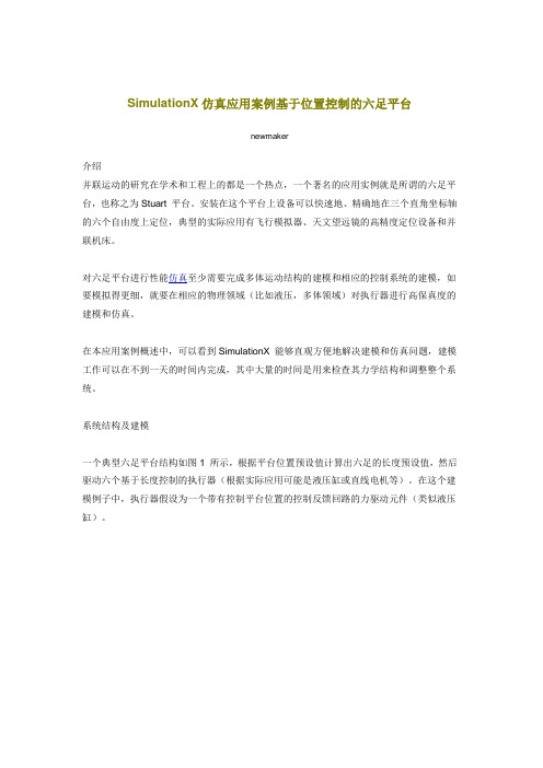
SimulationX仿真应用案例基于位置控制的六足平台newmaker介绍并联运动的研究在学术和工程上的都是一个热点,一个著名的应用实例就是所谓的六足平台,也称之为Stuart 平台。
安装在这个平台上设备可以快速地、精确地在三个直角坐标轴的六个自由度上定位,典型的实际应用有飞行模拟器、天文望远镜的高精度定位设备和并联机床。
对六足平台进行性能仿真至少需要完成多体运动结构的建模和相应的控制系统的建模,如要模拟得更细,就要在相应的物理领域(比如液压,多体领域)对执行器进行高保真度的建模和仿真。
在本应用案例概述中,可以看到SimulationX能够直观方便地解决建模和仿真问题,建模工作可以在不到一天的时间内完成,其中大量的时间是用来检查其力学结构和调整整个系统。
系统结构及建模一个典型六足平台结构如图1 所示,根据平台位置预设值计算出六足的长度预设值,然后驱动六个基于长度控制的执行器(根据实际应用可能是液压缸或直线电机等)。
在这个建模例子中,执行器假设为一个带有控制平台位置的控制反馈回路的力驱动元件(类似液压缸)。
图1:六足平台机械模型六足平台的机械部分是由SimulationX的3D 力学库的元件组成,如1D/3D 转换接口元件(形如液压缸),球体和一个通过SimulationX的外部CAD模型输入接口输入的复杂Cessna 飞机3D 模型。
该接口可以自动计算飞机模型的质心和惯性张量,1D/3D 转换接口元件的1D 边连接从控制器来的控制力。
预调和坐标变换为了控制平台的运动,规定了平台每个自由度上的位置信号,这些信号需转换成六个执行器的长度信号,通过矢量和矩阵操作可以很好地描述转换算法。
因为SimulationX提供了自己的编程语言——ITI-MDL,一种基于Modelica的建模语言,在信号处理模块中的信号可以是矢量形式,因此,使用imulationX可以很方便的完成上述任务,进行易于理解的建模设计,如图2 所示。


MFG226585Become a Fusion Simulation Expert in 60 MinutesDr. Shekar SubAutodesk IncDescriptionFusion Simulation software offers a rich set of analysis types to simulate real-world problems. Whether it’s simple static stress, optimizing a shape to reduce weight, or simulating a bird hitting an airplane, it’s all there. One of the biggest challenges is to set up the simulation properly so the results are reasonable. Interpretation of results to selecting the best alternative for manufacturing is another challenge. While demystifying simulation with tips and tricks from community forums, we will also highlight the pitfalls one needs to avoid. Collaboration and knowledge sharing is key to mastering simulation tools.Speaker(s)Shekar is a long timer of Autodesk and was recently the lead for Fusion Simulation. He has worked on various products at Autodesk like MDT, Inventor, and Fusion. He is one of the authors of the book, "Mastering Autodesk Inventor 2009 and Autodesk LT 2009", Wiley Publishing. His educational background includes bachelors, masters and doctorate degrees in mechanical engineering. He completed the Advanced Certificate for Executives in Management, Innovation & Technology program at Sloan School of management, Massachusetts Institute of Technology, Boston. He teaches classes at Autodesk University and is a frequent contributor to the Fusion Community forum. He volunteers for the FIRST robotics programs.IntroductionA vast amount of knowledge exists on the internet on Fusion Simulation. Youtube has videos about Fusion Simulation that are very helpful. Instead of rewriting a whole new handout I’m providing links about Fusion Simulation.Figure 1: Simulation StepsAbout Fusion360 Simulation: Learn as to why you need to do simulation and the value behind it.Figure 2: Fusion Simulation User InterfaceThe Simulation toolbar is a good starting place to familiarize yourself with all the commands needed for Simulation analysis.1. SimplificationRemove any unneeded geometry for your simulation. During this phase, strategize and plan to figure out what geometry needs to remain in the model for simulation.•Unneeded Fillets•Embossed Text•Actual threads•Leverage symmetry•Consider body/components that could be approximated by point massesFigure 3: Base Model, Simulation models and studies2. StudiesFigure 4: Simulation studiesThere are 8 different studies that you can select from to do your analysis. This provides step-by-step procedure to setup an LSS analysis. Tip: Create & then Edit• 2.1 How to create a study?• 2.2 Static Stress• 2.3 Modal frequencies• 2.4 Structural Buckling• 2.5 Thermal:• 2.6 Thermal Stress• 2.7 Shape Optimization• 2.8 Non Linear Static Stress• 2.9 Event SimulationFigure 5: Main study types3. MaterialsSimulation Materials may be different than Model materials. You can create your own custom material.Tip: Ctrl to add rows in Study Materials dialog. Shift to select a bunch of rows. RMB on a material in the browser to access the Study Materials command, all components that use the same material are automatically preselected4. ConstraintsFigure 6: Constraint typesTo restrict the model to a particular location apply Constraints. Apply any of the four different constraints. Tip: In some situations, partially constrain the model and use the Remove rigid body modes option. Solver will apply an acceleration load to keep model statically stable. 5. LoadsFigure 7: Main Load typesHow much load does the model need to resist? Apply any of the six different Structural Loads needed for your simulation.• 5.1 Load Cases Study different load cases and evaluate how the model performs. Tip: Double-click activates a load case. Cannot have 0 LCs• 5.2 How to assign a point mass: Substitute geometry with a point-mass or create a point mass to idealize non-created geometry. Tip: Which input field corresponds to which offset direction? Drag a manipulator arrow. Then, notice which Distance field has achanging value while you are dragging the arrow.• 5.3 How to assign global loads(Linear, Angular):Learn how to apply linear acceleration, angular velocity, and angular acceleration loads.6. ContactsFigure 8: Contact types and their propertiesLoads need to transfer across bodies so run Automatic contacts and create manual contacts where necessary.Figure 9: A comparison of different types of contacts7. MeshingFigure 10: Element typesGood quality Meshing is key to produce good results. Understanding node and element types.Figure 11: Aspect ratio and maximum turn angle 8. Pre-CheckFigure 12: Pre-check warnings and their meanings Pre-check your studies before Solving and saves time.9. SolveFigure 13: Solve dialog•9.1: Solve dialog: One stop dialog to do local or cloud solves. Also manage cloud credits. Tip: To resolve a solved study, uncheck and check the checkbox next to a load or constraint. No CC charged for cancelled solves. You can only cancel 1 job at a time•9.2: Solve Status: Display status of simulation jobs•9.3: Solve Details: Details of mesh for troubleshooting10. ResultsFigure 14: Results legendVisualize results Tip: You can specify the desired result on which to base the convergence test regardless of whether you are using a refinement preset or custom settingsFigure 15: Result types for various types of studies10.1 : Display10.2 : Animate10.3 : Display Minimum and Maximum value labels10.4 : Create Slice Plane10.5 : Surface Probes10.6 : Point Probes10.7 : Legend10.8 : Reactions10.9 : Deformation Scale10.10 : Comparing Simulation Results10.11 : Results DetailsFigure 16: Safety factor resultTip: A safety factor of <=1.0 means it will fail and not good. For example, an elevatorshould be designed using higher safety factors than a bracket used to mount a camera.Tip: Contact Pressure results are generated only where Separation contact is defined between two adjacent parts of a model. Contact pressure results are not computed for any other contact type (such as Bonded, Rough, or Sliding).Figure 17: Result detailsTip: Use Dynamic Content (Javascript) option which provides collapsible sectionsTip: Compare workspace available after results generationCompare workspace video11. ConclusionHere is a link for tutorials hands-on exercises.DemoFigure 18: LSS and SO studies demo •How create a Static Stress Analysis and Solve?•How to create a Shape Optimization study and Solve?。
H-17PRESSOSTATOS ECONÔMICOS INDUSTRIAISe Ajuste Fácil com Parafuso de Ajuste de Travamento e Design Industrial Reforçadoe Conexão Fêmea Padrão de ½" para Conduíte para Terminação ElétricaA série PSW-800 inclui pressostatos econômicos com ponto de ajuste facilmente regulável com parafuso de ajuste de travamento. Apresentam design de pistão vedado ou diafragma-pistão ideal para ambientes severos. T odos os modelos vem com fios condutores de 300 mm (12") comcódigo de cores e uma conexão fêmea para conduíte de ½" para ligações elétricas.ESPECIFICAÇÕESRepetibilidade do Ponto de Ajuste: Modelos com Diafragma (PSW-801 a PSW-807): ±1% do spanModelos com Pistão (PSW-808 a PSW-811): ±1,5% do span Histerese/Banda Morta:Veja a tabela "Para fazer o pedido" a direita Classificação do Contato: máximo de 5 A a 125/250 VCA, contatos serrilhados de prata 3 A máx. a 28 VCCIntervalo de Temperatura: -20 a 75°C(-4 a 167°F) (intervalo do vácuo); -30 a 75°C (-22 a 167°F) (500 psi e abaixo); -40 a 75°C (-40 a 167°F) (600 psi e acima)Efeitos Térmicos: <1% para alteração de 25°C (45°F)Pressão de Teste: Veja a tabela "Para fazer o pedido"Pressão de Ruptura: 2 x a pressão de teste Tipo de Sensor:PSW-801 a PSW-807: pistão-diafragmaPSW-808 a PSW-811: pistão vedado Peças Úmidas:Igual ou Inferior a 500 psi: Latão, Buna-NIgual ou Superior a 600 psi: Latão, Buna-N e aço inoxPorta de Pressão: ¼ MNPTConexão Elétrica: fios condutores livres de 300 mm (12") com conexão fêmea para conduíte de ½"Carcaça: de plástico, aberta Peso: 0,4 kg (0,95 lb)Exemplo de Pedido: pressostato de 10 a 50 psi PSW-804 com intervalo de banda morta de 1,5 a 6,0 psi e pressão de teste de 1000 psi.(1.14)HEX 38 DIA.305 (12) FREELEADS STANDARD 1/2 NPT FEMALE CONDUIT FITTING Standard Model29Intervalos de Vácuo a 7500 psiPSW-805,em tamanho inferior ao real.Série PSW-800CONEXÃO FÊMEA ½ NPT P ARACONDUÍTEFIOS CONDUTORES LIVRES P ADRÃO 305 (12)HEX. 29(1,14)38 (1,5)。