YT600-ARM主机设置说明书
- 格式:pdf
- 大小:4.81 MB
- 文档页数:24

t © Vibro-Meter SA / 268-101 / 04.06 / E1 / 5VM600Configuration SoftwareConfiguration Software for VM600 SeriesMachinery Protection Systems (MPS)FEATURES]Graphical User Interface software allowing maximum ease of use ]Running under Windows 98/NT/2000/XP/2003 Server]On-line Help information included ]Available in 3 languages (English, French, German)]Delivered with instruction manual on CD-ROM (in PDF format)MPS application software splash screent d r a ft MPS1 & MPS2VM600 Configuration Software© Vibro-Meter SA / 268-101 / 04.06 / E 2 / 5DESCRIPTIONVibro-Meter has developed two configuration software packages for use with the VM600 series Machinery Protection Systems (MPS). The packages run under Windows 98/NT/2000/XP/2003 Server and are menu-driven for ease of use. MPS1 and MPS2 allow stand-alone configuration of MPC 4 and AMC 8 cards, via the cards’ serial connectors. Alternatively, if the cards are installed in a networked VM600 rack, i.e. one containing a modular CPU card (type CPU M) used for rack control and communication, they can be configured in "one-shot" mode using an Ethernet TCP/IP link from the PC to the CPU M.All major parameters concerning the speed and vibration channels processed by the cards can be configured. This includes the input of sensor characteristics, the choice of the type of vibration monitoring to perform, the definition ofmeasurement units, rectification types, alarm levels, etc.MPS2 is a configuration, visualization and trending package for MPC 4 and AMC 8 cards installed in a networked VM600 rack.It has the same configuration functionality as MPS1 plus additional data recording and display features. Data measured can be stored in a database and recalled later for trend analysis. Up to 50,000 data records can be stored using a cyclic ‘first-in-first-out’ method. The period of time that database records can cover depends on the data acquisition rate you have specified. These features let you display a number of different charts showing the real-time display of sensor values or alternatively, graphs for trend analysis. The following charts can be displayed :Configuration screen for a processing channelConfiguration screen for an MPC 4 cardr s t d r a f t © Vibro-Meter SA / 268-101 / 04.06 / E 3 / 5MPS1 & MPS2VM600 Configuration Software1.Bar chart (real-time values)Up to 8 bars can be displayed per page. Direct access to other pages available. Status of all bars on all pages can be seen at a glance.2.Strip chart (real-time values)Up to 16 lines can be displayed per page. Direct access to other pages available. Status of all lines on all pages can be seen at a glance. Zoom facilities and print function available.DESCRIPTION (Continued)Bar charts showing real-time display of monitored signals Strip charts showing real-time display of monitored signalst d r a ft MPS1 & MPS2VM600 Configuration Software© Vibro-Meter SA / 268-101 / 04.06 / E 4 / 53.Trend chart (historic values)Feature available for analysis of historic data acquired at the user’s request.Up to 16 lines can be displayed. Zoom facilities and print function available.4.Long-term (averages) trend chartUp to 16 lines can be displayed. Zoom facilities, print function and data export facilities availableDESCRIPTION (Continued)Short term trend chartLong term (averages) trend chart© Vibro-Meter SA / 268-101 / 04.06 / E 5/ 5MPS1 & MPS2VM600 Configuration SoftwareIn this publication, a dot (.) is used as the decimal separator and thousands are separated by spaces. Example : 12 345.678 90. Although care has been taken to assure the accuracy of the data presented in this publication, we do not assume liability for errors or omissions. We reserve the right to alter any part of this publication without prior notice.Sales officesYour local agentHead officeVibro-Meter has offices in more than 30 countries. For a complete list, please visit our website.Vibro-Meter SARte de Moncor 4P.O. BoxCH-1701 FribourgSwitzerland Tel: +41 26 407 11 11Fax: +41 26 407 13 01To order please specify :Note : “SSs” represents the firmware (embedded software) version.When ordering please also specify:Code 1 : 01=English, 02=French, 03=German (the language required)Code 2 : n=number of copies (how many paper copies of the user manual you require)Code 3: 00=MPC 1 not supported, 01=MPC1 supportedFor example: 209-500-100-SSs /01 /03/ 00 would request: MPS 1 software in English, with 3 user manuals and a MPC 1 card is not supported.HARDWARE REQUIREMENTSMinimum Computer Configuration•200 MHz, Pentium based personal computer •One 9-pin serial port •32 MByte memory•Ethernet port (TCP/IP)•200 MByte hard disk space free •Windows 98/NT/2000/XP/2003 Server •CD-ROM drive •VGA monitorPrinter•Any Windows compatible printerORDERING INFORMATIONTypeDesignationOrdering NumberMPS1Configuration Software for VM600 Protection System209-500-100-SSsMPS2Configuration and Trending Software for VM600 Protection System209-500-200-SSs。

System Configuration and order-information GuideRX600 S2October 2006®CD-ROM DriveHard Disk BaySystem FanDisplay 5 inch BaySerial Port Display 10/100/1000Base T ConnectorPCI SlotPower SupplyCPUMemory Expansionfront sideThis document contains basic product and configuration information that will enable you to configure your system.Only these tools will ensure a fast and proper configuration of your PRIMERGY server or your complete PRIMERGY Rack system.You can configure your individual PRIMERGY server in order to meet your specific requirements.Please follow the lines. If there is a junction, you can choose which way or component you would like to take.Go through the configurator by following the lines from the top to the bottom.The color of the junction means as follows.[Single-Core CPU models]4-Way Processor Rack ServerBase Unit PGUR6024APGUR6022APGUR6026ACPUFrequencies 64-bit Intel® Xeon® MP 3.66GHz64-bit Intel® Xeon® MP 3.16GHz64-bit Intel® Xeon® MP 3.33GHzSecond-Level-Cache 1MB 1MB Third-Level-Cache -8MBMulti-Processormax. 4 (2 for standard)Front-Side-Bus 667MHz Chipset Intel® E8500MemoryStandard 2GB (1GB ECC DDR2 SDRAM DIMM x 2)Maximum *132GB (2GB ECC DDR2 SDRAM DIMM x 16) when Memory Expansion Board (PG-RB105) is appliedGraphics Controller ATI Radeon 7000M, VRAM:16MB Resolution *2640x480/800x600/1024x768/1280x1024 dotInternal Bays Number of bays 5 (1" Height)3.5 inch Available HDD *373.4GB (PG-HDH71V) 10krpm, U320 SCSI HDD146.8GB (PG-HDH41V) 10krpm, U320 SCSI 300.0GB (PG-HDH31V) 10krpm, U320 SCSI 73.4GB (PG-HDH75V) 15krpm, U320 SCSI 146.8GB (PG-HDH45V) 15krpm, U320 SCSIStandard -Maximum *31.5TB (300.0GB x 5)5 inch Bay1CD-ROM/DVD-ROM CD-ROM (Max. 24 ATAPI): standard, DVD-ROM: optionalPCI SlotsPCI-X (64bit/100MHz) 2 (non hot plug)PCI-X (64bit/133MHz) 1 (hot plug)PCI-Express (x8) 1 (hot plug)PCI-Express (x4)3 (hot plug)RAID Controller onboard, 256MB Cache, BBUSCSI Controller Ultra320 SCSI x 2chFDDoptional *5Network Controller (onboard) 2 ports (1000 BASE-T/100 BASE-TX/10BASE-T)InterfacesDisplay x 2 (Analog RGB) *6, Serial Port (D-SUB 9pins) x 1,USB x 5(Front : x 3,Rear : x 2) (ver. 1.1) *5, *7Server Management Software ServerView (Standard)Power supplyVoltageAC 200VPower consumption 1100W / 3960kJ/h (max.)Redundant power supplystandard (1+1)Redundant Fanstandard (2+2)Dimensions (W x D x H (mm) )447 (482.6 incl. protruding parts )(W) x 706 (737 incl. protruding parts )(D) x 176 (4U) (H)Weight50kg (max.)Environmental Conditions Temperature10-35°C / Humidity 20-80% (non condensing)OS Support *4Windows Server 2003, Standard Edition / Windows Server 2003, Enterprise Edition Windows Server 2003, Standard x64 Edition / Windows Server 2003, Enterprise x64 EditionWindows® 2000 Server/Windows® 2000 Advanced ServerRed Hat Enterprise Linux AS (v.3 for x86)Red Hat Enterprise Linux AS (v.4 for x86) / Red Hat Enterprise Linux AS (v.4 for EM64T)Attached tool (Standard)ServerStart (Setup Support tool)*1. Available memory capacity will be changed by the type of OS. Please find more details in Notes[Memory OS Compatibility List].*2. Resolution is determined by functions of the display monitor and OS.*3. HDD capacity is calculated according to the formulas 1GB=10003 byte and 1TB=10004 byte.*4. Drivers for Linux are not attached. Please download and use drivers of the following URL./global/services/computing/server/ia/driver/*5: One USB-FDD is required as a minimum in multiple servers. It is necessary to procure USB-FDD separately.USB-FDD can be connected to base unit with USB extension cable attached as standard.*6: Front and rear display connectors cannot be used at the same time.The Front display connector cannot be used with Windows® 2000 Server or Windows® 2000 Advanced Server.*7: PS/2-keyboard and PS/2-mouse can be connected to base unit with USB-PS/2 conversion cable.TypeData Sheet[Dual-Core CPU model]Type4-Way Processor Rack ServerBase Unit PGUR6028ACPU Frequencies Dual Core Intel® Xeon® 7040 3GHzSecond-Level-Cache2x2MBThird-Level-Cache-Multi-Processor max. 4 (2 for standard)Front-Side-Bus667MHzChipset Intel® E8500Memory Standard2GB (1GB ECC DDR2 SDRAM DIMM x 2)Maximum *132GB (2GB ECC DDR2 SDRAM DIMM x 16) when Memory Expansion Board (PG-RB105) is applied Graphics Controller ATI Radeon 7000M, VRAM:16MBResolution *2640x480/800x600/1024x768/1280x1024 dotInternal Bays Number of bays 5 (1" Height)3.5 inch Available HDD *373.4GB (PG-HDH71V) 10krpm, U320 SCSIHDD146.8GB (PG-HDH41V) 10krpm, U320 SCSI300.0GB (PG-HDH31V) 10krpm, U320 SCSI73.4GB (PG-HDH75V) 15krpm, U320 SCSI146.8GB (PG-HDH45V) 15krpm, U320 SCSIStandard-Maximum *3 1.5TB (300.0GB x 5)5 inch Bay1CD-ROM/DVD-ROM CD-ROM (Max. 24 ATAPI): standard, DVD-ROM: optionalPCI Slots PCI-X (64bit/100MHz) 2 (non hot plug)PCI-X (64bit/133MHz) 1 (hot plug)PCI-Express (x8) 1 (hot plug)PCI-Express (x4) 3 (hot plug)RAID Controller onboard, 256MB Cache, BBUSCSI Controller Ultra320 SCSI x 2chFDD optional *5Network Controller (onboard) 2 ports (1000 BASE-T/100 BASE-TX/10BASE-T)Interfaces Display x 2 (Analog RGB) *6, Serial Port (D-SUB 9pins) x 1,USB x 5(Front : x 3,Rear : x 2) (ver. 1.1) *5, *7Server Management Software ServerView (Standard)Power supply Voltage AC 200VPower consumption1100W / 3960kJ/h (max.)Redundant power supply standard (1+1)Redundant Fan standard (2+2)Dimensions (W x D x H (mm) )447 (482.6 incl. protruding parts)(W) x 706 (737 incl. protruding parts)(D) x 176 (4U) (H) Weight50kg (max.)Environmental Conditions Temperature10-35°C / Humidity 20-80% (non condensing)OS Support *4Windows Server2003, Standard Edition / Windows Server2003, Enterprise EditionWindows Server2003, Standard x64 Edition / Windows Server2003, Enterprise x64 EditionRed Hat Enterprise Linux AS (v.3 for x86)Attached tool (Standard)ServerStart (Setup Support tool)*1. Available memory capacity will be changed by the type of OS. Please find more details in Notes[Memory OS Compatibility List].*2. Resolution is determined by functions of the display monitor and OS.*3. HDD capacity is calculated according to the formulas 1GB=10003 byte and 1TB=10004 byte.*4. Drivers for Linux are not attached. Please download and use drivers of the following URL./global/services/computing/server/ia/driver/*5: One USB-FDD is required as a minimum in multiple servers.It is necessary to procure USB-FDD separately.USB-FDD can be connected to base unit with USB extension cable attached as standard.*6: Front and rear display connectors cannot be used at the same time.The Front display connector cannot be used with Windows® 2000 Server or Windows® 2000 Advanced Server.*7: PS/2-keyboard and PS/2-mouse can be connected to base unit with USB-PS/2 conversion cable.*Components installed as standard configuration marked in grey.PCI PCI-XPCI PCI-XExpressExpressInternal/External SCSI ConnectorExternal array*1. The maximum number of LAN cards is 4.*2 In case that 2 RAID controller cards are mounted, the following pattern1 and pattern2 are available. ( pattern 3 is not available.)High Low -○○×3○○2○ ○1○○ pattern 267---slot mount priorityavailable/ not available133 (*1)23(*1)Remarks4Max No.of Mount44 (*1)-71-3----4456-Full Height43.3V3.3V x8socketPCI Slot Priority122 (*2) 3 (*2)1----PG-128PCI/64bit ----11-PCI/64bitMount PriorityPGB286PCIExpress (x4)PCIExpress (x4)Fibre Channel ControllerEth. Ctrl dual 1000-BASE-TRemote Service BoardPG-FC201PG-286PGBFC201RAID Ctrl 2-Channel 128MB w/BBUPG-RSB104PGBRSB104--2PGB128PG-142E3SCSI Ctrl U160PGB142E32-2-Bus3x8laneMountable CardsEth. Ctrl 1000-BASE-T CuEth. Ctrl 1000-BASE-SX Fibre LC -Eth. 2x 1000-BASE-T Cu-PGB1892PG-1892PCI-X/64bitPG-1882PG-1862--1---22364bit/133M Hz x4lane 64bit/100MHz321-x4socket3-3PCI-X/64bit PCI-X/64bit1--22(*1)-1HighLowHigh LowProcessor Xeon 7040 3.0GHz/2x2MB PG-FG30KPGBFG30K (for CTO/ for 1st additional CPU) PGBFG30K2 (for CTO / for 2nd additional CPU)*. This option is available when the processors of the base unit are Processor Xeon 7040 3.0GHz/2x2MB.Processor Xeon MP 3.33GHz/8MB PG-FG209PGBFG209 (for CTO/ for 1st additional CPU) PGBFG2092 (for CTO / for 2nd additional CPU)*. This option is available when the processors of the base unit are Processor Xeon MP 3.33GHz/8MB.Processor Xeon MP 3.66GHz/1MB PG-FG208PGBFG208 (for CTO/ for 1st additional CPU) PGBFG2082 (for CTO / for 2nd additional CPU)*. This option is available when the processors of the base unit are Processor Xeon MP 3.66GHz/1MB.Processor Xeon MP 3.16GHz/1MB PG-FG207PGBFG207 (for CTO/ for 1st additional CPU) PGBFG2072 (for CTO / for 2nd additional CPU)*. This option is available when the processors of the base unit are Processor Xeon MP 3.16GHz/1MB.Standard Memory BoardMemory Module-2GB (1GB DIMM x 2)PG-RM2BDPGBRM2BD (for CTO)Memory Expansion Board Memory Module-4GB (2GB DIMM x 2)PG-RM4BDPGBRM4BD (for CTO)Memory Module Conversion kit-4GB (2GB DIMM x 2)PGBRU4BD (for CTO)4GBMax: 3Memory Module-2GB (1GB DIMM x 2)PG-RM2BDMemory Module-4GB (2GB DIMM x 2)PG-RM4BD1. The installation order of Memory Expansion Board is as following.Memory Expansion Board A(standard) → Memory Expansion Board B → Memory Expansion Board C → Memory Expansion Board D 2. Two same capacity DIMM cards should be installed at a time.Two different capacity DIMM cards shouldn't be installed at a time. Only one DIMM card shouldn't be installed at a time.3. The installation order of Memory is as following.(1) [DIMM slot 1A,1B(Bank1)] → [DIMM slot 2A,2B(Bank2)](2) [Memory Module-2GB(1GB-DIMMx2)] → [Memory Module-4GB(2GB-DIMMx2)]4. Available Memory CapacitySame as the size of mounted memory (Note: "0.1-1.0GB" which is being used for PCI resource management Size of Mounted Memory minus "0.1-1.0GB"depends on the type and the number of installed memory modules.Mounted MemoryAvailable Memory Area2.0GB CPUdummy dummy CPU CPU dummy 4.0~32.0GBCPUCPUCPU23CPU CPU 4CPU1socket CPU2socket CPU3socket CPU4socket CPU the number of CPUs5. Spare Memory FunctionSpare Memory function assigns Spare Memory by Memory Expansion Board.(1) Memory capacity of Bank1 and Bank2 should be same.(2) Spare Memory structure should be made on all installed Memory Expansion Board.(3) If spare Memory function is applied, Memory mirroring function and Memory RAID function cannot be applied.(4) Available memory capacity is the half of installed memory.The Memory installation for Spare Memory function is as following.0 : Memory is installed.- : Memory is not installed.6. Memory Mirroring FunctionMemory Mirroring function assigns mirror set by 2 Memory Expansion Board.(1) Memory capacity of 2 Memory Expansion Board of mirror set should be same.(2) The structure of mirror set is as following.- When 2 Memory Expansion Board are installed : mirror set #1 (Memory Expansion Board A + Memory Expansion Board B)- When 4 Memory Expansion Board are installed : mirror set #1 (Memory Expansion Board A + Memory Expansion Board B)mirror set #2 (Memory Expansion Board C + Memory Expansion Board D)(3) If Memory mirroring function is applied, spare Memory function and Memory RAID function cannot be applied.(4) Available memory capacity is the half of installed memory.The Memory installation for Memory Mirroring function is as following.0 : Memory is installed.- : Memory is not installed.7. Memory RAID FunctionMemory RAID function assigns Memory RAID by 4 Memory Expansion Board.(1) Memory capacity of all Memory Expansion Board should be same.(2) If Memory RAID function is applied, spare Memory function and Memory mirroring function cannot be applied.(3) Available memory capacity is three quarters of installed memory.The Memory installation for Memory RAID function is as following.0 : Memory is installed.- : Memory is not installed.8. Hot Plug FunctionIf Memory mirroring function or Memory RAID function is applied, hot plug function of Memory Expansion Board is available.Memory Expansion Board B Memory Expansion Board CMemory Expansion Board D Bank21A 1B 2A 2B 1A 1B 2A 2B 1A Bank1Bank2Bank1Bank21A 1B 2B 002A 00Bank1Bank2Bank100Memory Expansion Board A 0000000000Memory Expansion Board A Memory Expansion Board B Bank1Bank2Bank1Bank21A 1B 2A 2B ----00000000000Memory Expansion Board C Bank1Bank21A 1B 2A 2B --------0000000Memory Expansion Board D Bank1Bank21A 1B 2A 2B ------------0001B 2A 2B 1A 1B 2A 2B 00--00----------00--00--00--00--0000000-0------000000000mirror set #1mirror set #200-0Memory Expansion Board A Memory Expansion Board B Memory Expansion Board C Memory Expansion Board D Bank1Bank2Bank1Bank2Bank1Bank2Bank1Bank21A 1B 2A 2B 1A 1B 2A 2B 1A 1B 2A 2B 1A 1B 2A 2B 00--00--00--00--000000000(''1) Wide Backup Devices: PG-DT501/PG-VX201(''2) Narrow Backup Devices: None(''3) Wide Backup Devices: PG-DT501/PG-LT201/PGBLT201/PG-VX201(''4) Backup Devices which occupies 2 bays: NoneTape Drv DAT72 36GB internal PG-DT501SCSI Cable 1.0m PGBDT501 (for CTO)Tape Drv LTO2 Ultrium2 200GB PG-LT201PGBLT201 (for CTO)Tape Drv VXA-2 80GB PG-VX201HDD HDDSCSI Cable HDCI 1.5mRemote Service Board Twist Pair CablePG-RSB104PGBRSB104 (for CTO)Specifications are subject to change without notice. For the latest detailed information, contact your local representative. All brand names and product names are trademarks and registered trademarks of their respective holders.©2006 Fujitsu Limited. All rights reserved. Printed in Japan.Global Business Development & MarketingBusiness Strategy & PlanningSystem ProductsURL 。

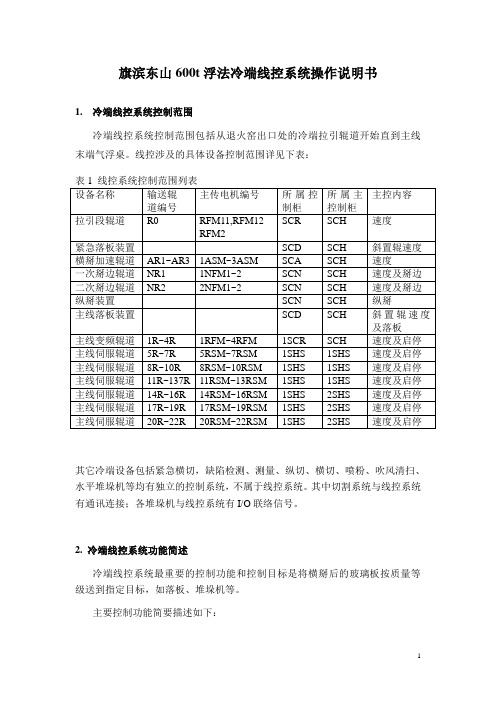
旗滨东山600t浮法冷端线控系统操作说明书1. 冷端线控系统控制范围冷端线控系统控制范围包括从退火窑出口处的冷端拉引辊道开始直到主线末端气浮桌。
线控涉及的具体设备控制范围详见下表:其它冷端设备包括紧急横切,缺陷检测、测量、纵切、横切、喷粉、吹风清扫、水平堆垛机等均有独立的控制系统,不属于线控系统。
其中切割系统与线控系统有通讯连接;各堆垛机与线控系统有I/O联络信号。
2. 冷端线控系统功能简述冷端线控系统最重要的控制功能和控制目标是将横掰后的玻璃板按质量等级送到指定目标,如落板、堆垛机等。
主要控制功能简要描述如下:线控系统的控制程序就是模拟生产线的实际运行状态,以辊道运行速度、玻璃行走距离、玻璃板长度、玻璃质量等级为主要参数,形成全线玻璃信息队列。
并由此实现玻璃全线自动跟踪控制。
每片玻璃在横掰后,将包含了板规格、玻璃等级信息的玻璃板加入到玻璃队列,并开始以辊道的运行速度计算其在生产线的位置,直到玻璃落板、堆垛、或走出主线进入到气浮桌为止。
各玻璃运行到各特定的位置上将触发不同的控制输出信号,如加速辊道的变速控制,掰边、纵掰电磁阀动作控制,落板装置动作控制,堆垛辊道减速、爬行定位及堆垛控制,辊道联锁停车定位控制等等。
其中,玻璃板规格数据由切割系统通讯传来。
玻璃等级信息通过缺陷检测及打标信号提供。
辊道速度由人工设定或由线控系统根据退火速度自动计算。
整个玻璃队列的移动只受辊道运行状态和运行速度影响。
生产线上的光电开关主要用于玻璃位置的实际校验。
综上所述,线控系统的核心是玻璃队列的模拟控制,其关键点主要是二个:横掰位置的准确控制:即横掰辊抬起并掰断玻璃的重复位置要求较高,否则进入玻璃队列的初始位置偏差会变大,不利于后续的跟踪控制。
横掰位置的调节是在切割系统上操作的,需要相关操作人员注意。
同时横掰汽缸的气压应保持相对稳定。
辊道的运行状态要准确,包括辊道运行状态信号的反馈要准确,辊道变频器、伺服驱动器中与速度、加减速相关的参数值必须按供货商的要求进行准确设置,不得随意变更。

TR600数字式应变电阻传感器变送器使用说明书LONGTEC 珠海市长陆工业自动控制系统有限公司用前须知:u初次使用前,请详细阅读本说明书,现场使用许多疑难问题,在本说明书中将找到答案。
u使用前,请检查称重系统其他部件是否匹配。
u使用本仪表,注意防晒、防雨水、防撞击。
u使用本仪表,请尽可能配备常用安装、检修工具:小型一字螺丝刀,数字式万用表,称重传感器模拟器(mV信号发生器)。
目录用前须知: (1)1概述 (5)1-1简介 (5)1-2有关术语 (5)1-3特点 (5)2技术参数 (6)2-1一般参数 (6)2-2数字部分 (6)2-3模拟部分 (6)3安装 (7)3-1安装注意事项 (7)3-2变送器输入灵敏度 (7)3-3传感器与变送器之连接法 (8)3-4变送器最长可联接的称重信号电缆长度表 (8)3-5称重传感器接线方式 (8)3-6安装尺寸图(单位:MM) (8)4显示面板及按键说明 (9)4-1前面板及打开保护盖示意图 (9)4-2保护盖 (9)4-3接线端子说明 (10)4-4数码显示说明 (10)4-5在称重状态下各功能键的说明 (10)4-6波特率选择说明 (10)4-7ID地址选择说明 (10)5功能设置 (11)5-1参数设定 (11)5-1-1“FUNC”进入设定 (11)5-1-2“F10”零位跟踪时间 (12)5-1-3“F20”动态检测范围 (12)5-1-4“F30”RS232/485通讯输出速率 (12)5-1-5“F40”小数点选择 (13)5-1-6“F50”分度间距 (13)5-1-7“F6 0”最大量程 (13)5-1-8“F70”数字滤波 (14)5-2经由RS232/RS485接口设定功能(配RS232或RS485有此功能) (15)5-2-1零位跟踪范围 (15)5-2-2动态检测范围 (15)5-2-3RS232/RS485通讯输出速率 (15)5-2-4小数点 (15)5-2-5分度间距 (16)5-2-6最大量程 (16)5-2-7数字滤波 (16)6.仪表标定 (16)6-1标定的意义 (16)6-2操作 (17)6-2-1零位标定 (18)6-2-2秤量间距标定 (18)6-2-3标定错误提示 (19)6-3经由RS232/RS485接口标定(配RS232或RS485有此功能) (20)6-3-1 TR600可经由RS232/RS485接口直接调校 (20)7.称重定值比较量设置按键操作: (21)7-1设置参数步骤 (21)7-2经由RS232/RS485设定比较值(配RS232或RS485有此功能) (23)8.通讯参数的设定 (23)8-1通讯格式说明 (23)8-2波特率的设定 (25)8-3通讯ID地址的设定 (25)9.输入/输出 (25)9-1控制输入 (25)9-1-1输入接口(内置) (25)9-1-2输入接口与外接开关的联接 (26)9-1-3输入接口与PLC的联接......................................................................................错误!未定义书签。

600系列主机基本功能一、型号说明:600系列主机有以下几个型号:TTX6084、TTX6164、TTX6224、TTX6324,分别为8进4出、16进4出、24进4出,键盘为TTX600VJ (一主机可带4键盘)二、功能说明1、8、16、24、32路视频输入可选,标准为4路视频输出2、C 型控制方式(同轴视控)或D 型控制方式(RS485方式)3、带有视频环通输出4、128路报警输入,带报警联动功能,1个报警继电器输出(50V A )600系列键盘操作说明变速摇杆键盘,支持变速操作一 .键盘基本操作选择一个摄象机、视频序列和监视器1. nn + [CAMERA]:选择nn 号摄象机在当前监视器上进行操作(nn=1—32);2. nn + [SEQUENCE RECALL];选择一个预先编程好的视频序列(nn=1—4);3. 选择监视器:扭动钥匙,键盘显示PR ,再按[CAMERA],可改变监视器号,根据需要选择几号监视器;(或者是按住[CAMERA]保持5S ,然后再按[CAMERA],可改变监视器号,根据需要选择几号监视器)选择预置位4. nn + [PRESET RECALL]:调用一个预先编程好的预置位;(nn=1—16)5. [PRESET RECALL]:瞬时功能6. 操作杆: 控制云台水平、垂直方向功能;7.[LENS FUNCTIONS ]: 光圈开、关,聚焦远、近,视角大、小;8.[HOME]: 使云台回到初始点,即预置位1;[WASH]: 开启喷水器,[AUX2]:使用直流云台时,会使其速度加倍。
开关控制功能键[LENS SLOW]、[AUTO IRIS]、[LAMPS]、[CAMARA ON/OFF]、[WIPE]、[AUX1]分别为镜头慢速,自动光圈,灯光,摄象机开关,雨刮器,辅助功能键(以上各功能要求设备具有相应的功能才能实现)。
[ALL ON]、[ALL OFF]全开和全关功能,例如:[ALL ON] [WIPE]就是将所有的雨刷器都打开。
PT600安装设置手册PT600控制系统安装设置手册目录目录第一部分系统介绍简介4技术参数4典型应用4设备及配件装箱清单5端口说明6第二部分系统设置系统设置向导软件的安装7系统设置连接8确定设置用串口8选择设置方式9选择被控制设备的控制方式10选择被控制设备型号11RS232串口通信参数设置12被控制设备红外码类别识别13PT600面板按键功能设置14 PT600柜门探测功能设置15系统功能维护16增加功能17被控制设备RS232串口控制指令码设置18被控制设备红外码学习19延时时间设置20组合功能设置21最后一步22设置报告查看22保存设置22数据传输22第三部分设备连接PT600控制系统安装设置手册目录面板与主机连接示意图23 UPS系统连接示意图24投影机、门探连接示意图25计算机信号连接示意图26电动屏幕连接27第四部分技术支持常见故障及解决方法28技术支持途径29第五部分附录PT600面板安装尺寸30技术参数31编程电缆引脚定义32投影机控制接线图32系统功能表33 PT600控制系统安装设置手册第部分系统介绍第一部分系统介绍简介PT600控制系统是专为多媒体投影机设计的一套控制系统。
它与WISE DP700一样具有安装方便、操作简易、高度的稳定可靠、故障率极低等特点。
在功能上作了更进步的简化在信号切换上依靠投影机本身所带端口主要应用在些控制功能要求一步的简化,在信号切换上依靠投影机本身所带端口,主要应用在一些控制功能要求简单的多媒体教室建设中。
主要技术参数1.一路RS232/IR控制接口(复用)2.一路AC220V电源可控制输出(用于投影机供电,延时时间可设定)两路开关量信号探测口3.两路开关量信号探测口(UPS和门锁)4.四键式按键面板(键功能可自由设置)5.一路电动屏幕控制端口6.一路VGA信号输入,两路输出7.一路UPS开关控制端口8.两路电源输入(UPS和市电)典型应用一台具备VIDEO端口和RGB端口的投影机、一台PC机、一台视频展示台-4-PT600控制系统安装设置手册系统设置连接步骤:1、确认PT600主机开关处于OFF 状态。
HAT600P系列(HAT600P/HAT600PB/HAT600PI/HAT600PBI/HAT600PS)双电源自动切换控制器用户手册目次前言 (4)1概述 (6)2命名规范及型号对比 (7)2.1命名规范 (7)2.2型号对比 (7)3性能特点 (8)4规格 (9)5测量和显示数据 (11)6操作 (12)6.1指示灯描述 (12)6.2按键功能描述 (13)7屏幕显示 (14)7.1主显示 (14)7.2状态描述 (15)7.3主菜单 (19)8发电机组开停机操作 (20)8.1手动模式开停机 (20)8.1.1面板开停机 (20)8.1.2通讯遥控开停机 (20)8.2自动模式开停机 (20)8.2.1开机条件 (20)8.2.2两组发电机开停机 (21)8.2.3定时巡检开机 (22)8.2.4定时不开机 (22)9参数设置 (23)9.1说明 (23)9.2参数配置表 (23)9.3开关量输入口功能描述 (31)9.4开关量输出口功能描述 (32)9.5自定义组合输出 (34)9.6过流定时限与反时限设置 (35)10历史记录 (36)11黑匣子记录 (37)12谐波分析 (39)13开关操作运行 (40)13.1手动操作运行 (40)13.2自动操作运行 (40)13.2.1自投自复 (40)13.2.2自投不自复(互为备用有效) (41)13.2.3自投不自复(互为备用无效) (41)13.3同步合闸 (42)13.3.1S1同步合闸 (43)13.3.2S2同步合闸 (43)13.3.3手动同步合闸 (44)13.3.4自动同步合闸 (44)14ATS供电电源 (45)14.1直流供电 (45)14.2交流供电 (45)15非重要负载NEL控制 (47)15.1说明 (47)15.2自动操作 (47)15.3手动操作 (47)16通信配置及连接 (48)16.1说明 (48)16.2RS485通信口 (48)16.3USB通信口 (48)16.4ETHERNET通信口 (48)17端口定义 (50)17.1控制器端口描述 (50)17.2控制器供电说明 (52)17.2.1直流供电 (52)17.2.2交流供电 (52)17.3RS485连接说明 (52)18典型应用图 (54)19安装尺寸 (60)20故障排除 (61)前言表1 版本发展历史表2 本文档所用符号说明符号说明该图标提示或提醒操作员正确操作。
YT送丝机使用说明书成都振中电焊机厂邮政编码:厂址:成都外东西河镇南街105号电话:传真:首先感谢您购买本厂产品,从此您将同时拥有本厂优质的产品和优质的服务!为了正确和安全使用设备,使用前请仔细阅读使用说明书,如有疑问,请联系本厂技术支持部门。
目录1、产品描述 (2)2、技术参数 (3)3、安装 (4)4、操作 (4)5、维护 (5)6、故障及处理 (5)7、零部件清单 (7)8、随机文件 (11)9、附图(附后) (11)1、产品描述YT送丝机是埋弧焊专用送丝机构,适合直径范围为φ2.4~φ6的焊丝的送给。
配合MZ悬挂式控制器和ZX5或ZD5L弧焊整流器可以在龙门或悬臂焊接机上实现自动埋弧焊接。
订货时需注明送丝机是正向还是反向。
1.1、产品特点□采用方箱齿轮减速器。
□压丝弹簧行程大,焊丝压紧力调节范围大。
□电机和送丝机构绝缘,保证良好的电气绝缘性能。
□送丝轮两斜面均有齿,其中一面磨损后换一面可继续使用。
□送丝机可分正反成对使用。
1.2、外观图一YT送丝机(正)外观图YT送丝机(正)图示说明:1—L板(正);2—弯柄(正);3—铰链轴;4—轴承;5—固定块(正);6—螺套;7—弹簧;8—拉杆;9—滑块;10—校丝轮;11—支座;12—减速电机;13—送丝轮。
图二YT送丝机(反)外观图YT送丝机(反)图示说明:1—L板(反);2—弯柄(反);3—铰链轴;4—轴承;5—固定块(反);6—螺套;7—弹簧;8—拉杆;9—滑块;10—校丝轮;11—支座;12—减速电机;13—送丝轮。
2、技术参数(1)电机额定电压:110VDC(2)电机最大电流:≤2.1A(3)功率:165W(4)额定转速:20 rmp(5)最大送丝速度:3m/min(6)焊丝直径范围:φ2.4~φ6mm(7)外形尺寸:278×154×188(8)安装尺寸:4-M10螺孔,孔距110×25(9)重量:3、安装3.1、环境(1)环境温度:贮存时,-25℃~55℃运行时,-10℃~40℃(2)空气相对湿度:在40℃时,≤50%在20℃时,≤90%(3)使用场合应无严重影响运行的灰尘、酸碱、腐蚀性介质和易燃易爆物质。