DF3A5.6LFV中文资料
- 格式:pdf
- 大小:130.18 KB
- 文档页数:3
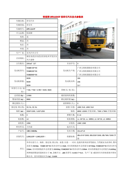
目录序号: 3
发动机生产商:广西玉柴机器股份有限公司广西玉柴机器股份有限公司
目录序号: 3
发动机生产商:广西玉柴机器股份有限公司发动机功率:250
目录序号: 3
广西玉柴机器股份有限公司
发动机生产商:
潍坊潍柴培新气体发动机有限公司
目录序号: 3
发动机生产商:广西玉柴机器股份有限公司
目录序号: 3
广西玉柴机器股份有限公司
发动机生产商:
潍坊潍柴培新气体发动机有限公司
276
目录序号: 3
广西玉柴机器股份有限公司
发动机生产商:
潍坊潍柴培新气体发动机有限公司
276
目录序号: 3
发动机生产商:广西玉柴机器股份有限公司。

挂壁机苏宁专供规格参数系列苏宁集团专供系列苏宁集团专供系列苏宁集团专供系列苏宁集团专供系列苏宁集团专供系列苏宁集团专供系列苏宁集团专供系列苏宁集团专供系列HP(匹数) 1HP 1HP 1HP 1HP 1.5HP 1.5HP 1.5HP 1.5HP型号室内机FTXS225NCSXFTXS225NCSSFTXS225NCSRFTXS225NCSWFTZS235NCSXFTZS235NCSSFTZS235NCSRFTZS235NCSW室外机RXS225NCSRXS225NCSRXS225NCSRXS225NCSRZS235NCSRZS235NCSRZS235NCSRZS235NCS遥控器ARC466A4 ARC466A4 ARC466A4 ARC466A4 ARC466A4 ARC466A4 ARC466A4 ARC466A4适用面积*1 制冷/制热㎡10~16/8~1510~16/8~1510~16/8~1510~16/8~1514~19/10~1714~19/10~1714~19/10~1714~19/10~17电源单相220V50Hz单相220V50Hz单相220V50Hz单相220V50Hz单相220V50Hz单相220V50Hz单相220V50Hz单相220V50Hz制冷量(min-max) kW2.5(1.3~3.2)2.5(1.3~3.2)2.5(1.3~3.2)2.5(1.3~3.2)3.5(1.25~4.0)3.5(1.25~4.0)3.5(1.25~4.0)3.5(1.25~4.0)制热量(min-max) kW3.4(1.3~4.8)3.4(1.3~4.8)3.4(1.3~4.8)3.4(1.3~4.8)4.2(1.4~5.6)4.2(1.4~5.6)4.2(1.4~5.6)4.2(1.4~5.6)APF(全年能源消耗效率)*2 W·h/(W·h)4.26 4.26 4.26 4.26 4.14 4.14 4.14 4.14尺寸(H×W×D) 室内机㎜283×868×21283×868×21283×868×21283×868×21283×868×21283×868×21283×868×21283×868×21室外机㎜550×658×275550×658×275550×658×275550×658×275550×765×305550×765×305550×765×305550×765×305重量室内机/室外机kg 9/31 9/31 9/31 9/31 9/35 9/35 9/35 9/35 *1 适用面积会因房间所在地区、结构、朝向等实际情况有所不同*2 APF依据国家能效标准GB21455-2013的测试方法得出系列苏宁集团专供系列苏宁集团专供系列苏宁集团专供系列苏宁集团专供系列苏宁集团专供系列苏宁集团专供系列苏宁集团专供系列苏宁集团专供系列苏宁集团专供系列苏宁集团专供系列苏宁集团专供系列苏宁集团专供系列HP(匹数) 1HP 1HP 1HP 1HP 1.5HP 1.5HP 1.5HP 1.5HP 1.5HP 1.5HP 1.5HP 1.5HP型号室内机FTXS225KCSS5FTXS225KCSX5FTXS225KCSR5FTXS225KCSW5FTXS235KCSS5FTXS235KCSX5FTXS235KCSR5FTXS235KCSW5FTZS235KCSS5FTZS235KCSX5FTZS235KCSR5FTZS235KCSW5室外机RXS225KCS5RXS225KCS5RXS225KCS5RXS225KCS5RXS235KCS5RXS235KCS5RXS235KCS5RXS235KCS5RZS235KCS5RZS235KCS5RZS235KCS5RZS235KCS5 遥控器ARC466A4ARC466A4ARC466A4ARC466A4ARC466A4ARC466A4ARC466A4ARC466A4ARC466A4ARC466A4ARC466A4ARC466A4适用面积*1 制冷/制热㎡10~16/8~1510~16/8~1510~16/8~1510~16/8~1514~19/10~1714~19/10~1714~19/10~1714~19/10~1714~20/10~1814~20/10~1814~20/10~1814~20/10~18电源单相220V50Hz单相220V50Hz单相220V50Hz单相220V50Hz单相220V50Hz单相220V50Hz单相220V50Hz单相220V50Hz单相220V50Hz单相220V50Hz单相220V50Hz单相220V50Hz制冷量(min-max) kW2.5(1.3~3.2)2.5(1.3~3.2)2.5(1.3~3.2)2.5(1.3~3.2)3.5(1.3~3.8)3.5(1.3~3.8)3.5(1.3~3.8)3.5(1.3~3.8)3.5(1.4~4.0)3.5(1.4~4.0)3.5(1.4~4.0)3.5(1.4~4.0)制热量(min-max) kW3.4(1.3~4.4)3.4(1.3~4.4)3.4(1.3~4.4)3.4(1.3~4.4)4.2(1.3~5.0)4.2(1.3~5.0)4.2(1.3~5.0)4.2(1.3~5.0)4.2(1.4~5.5)4.2(1.4~5.5)4.2(1.4~5.5)4.2(1.4~5.5)SEER(制冷季节能效比)*25.22 5.22 5.22 5.22 5.48 5.48 5.48 5.48 5.63 5.63 5.63 5.63 SEER(制冷季节能效比)*34.86 4.86 4.86 4.86 4.53 4.53 4.53 4.53 4.83 4.83 4.83 4.83 尺寸(H×W 室内机㎜283×868×210283×868×210283×868×210283×868×210283×868×210283×868×210283×868×210283×868×210283×868×210283×868×210283×868×210283×868×210×D)室外机㎜550×658×275 550×658×275550×658×275550×658×275550×658×275550×658×275550×658×275550×658×275550×765×285550×765×285550×765×285550×765×285重量室内机/室外机kg9/31 9/31 9/31 9/31 9/31 9/31 9/31 9/31 9/34 9/34 9/34 9/34*1 适用面积会因房间所在地区、结构、朝向等实际情况有所不同*2 SEER值依据国家生产标准GB7725-2004的测试方法得出*3 SEER值依据国家能效标准GB21455-2008的测试方法得出系列苏宁集团专供系列苏宁集团专供系列苏宁集团专供系列苏宁集团专供系列苏宁集团专供系列苏宁集团专供系列苏宁集团专供系列苏宁集团专供系列苏宁集团专供系列苏宁集团专供系列苏宁集团专供系列苏宁集团专供系列HP(匹数) 1HP 1HP 1HP 1HP 1.5HP 1.5HP 1.5HP 1.5HP 1.5HP 1.5HP 1.5HP 1.5HP型号室内机FTXS225KCSSFTXS225KCSXFTXS225KCSRFTXS225KCSWFTXS235KCSSFTXS235KCSXFTXS235KCSRFTXS235KCSWFTZS235KCSSFTZS235KCSXFTZS235KCSRFTZS235KCSW 室外机RXS225KCSRXS225KCSRXS225KCSRXS225KCSRXS235KCSRXS235KCSRXS235KCSRXS235KCSRZS235KCSRZS235KCSRZS235KCSRZS235KCS 遥控器ARC46ARC46ARC46ARC46ARC46ARC46ARC46ARC46ARC46ARC46ARC46ARC466A4 6A4 6A4 6A4 6A4 6A4 6A4 6A4 6A4 6A4 6A4 6A4适用面积*1制冷/制热㎡10~16/8~1510~16/8~1510~16/8~1510~16/8~1514~19/10~1714~19/10~1714~19/10~1714~19/10~1714~20/10~1814~20/10~1814~20/10~1814~20/10~18 电源单相220V50Hz单相220V50Hz单相220V50Hz单相220V50Hz单相220V50Hz单相220V50Hz单相220V50Hz单相220V50Hz单相220V50Hz单相220V50Hz单相220V50Hz单相220V50Hz制冷量(min-max)kW2.5(1.3~3.2)2.5(1.3~3.2)2.5(1.3~3.2)2.5(1.3~3.2)3.5(1.3~3.8)3.5(1.3~3.8)3.5(1.3~3.8)3.5(1.3~3.8)3.5(1.4~4.0)3.5(1.4~4.0)3.5(1.4~4.0)3.5(1.4~4.0)制热量(min-max)kW3.4(1.3~4.4)3.4(1.3~4.4)3.4(1.3~4.4)3.4(1.3~4.4)4.2(1.3~5.0)4.2(1.3~5.0)4.2(1.3~5.0)4.2(1.3~5.0)4.2(1.4~5.5)4.2(1.4~5.5)4.2(1.4~5.5)4.2(1.4~5.5)SEER(季节能效比)*25.22 5.22 5.22 5.22 5.48 5.48 5.48 5.48 5.63 5.63 5.63 5.63SEER(季节能效比)*34.86 4.86 4.86 4.86 4.53 4.53 4.53 4.53 4.83 4.83 4.83 4.83尺寸(H×W ×D) 室内机㎜283×868×210283×868×210283×868×210283×868×210283×868×210283×868×210283×868×210283×868×210283×868×210283×868×210283×868×210283×868×210 室外机㎜550×65550×65550×65550×65550×65550×65550×65550×65550×76550×76550×76550×768×275 8×275 8×275 8×275 8×275 8×275 8×275 8×275 5×285 5×285 5×285 5×285重量室内机/室外机kg9/31 9/31 9/31 9/31 9/31 9/31 9/31 9/31 9/34 9/34 9/34 9/34*1 适用面积会因房间所在地区、结构、朝向等实际情况有所不同*2 SEER值依据国家生产标准GB7725-2004的测试方法得出*3 SEER值依据国家能效标准GB21455-2008的测试方法得出。
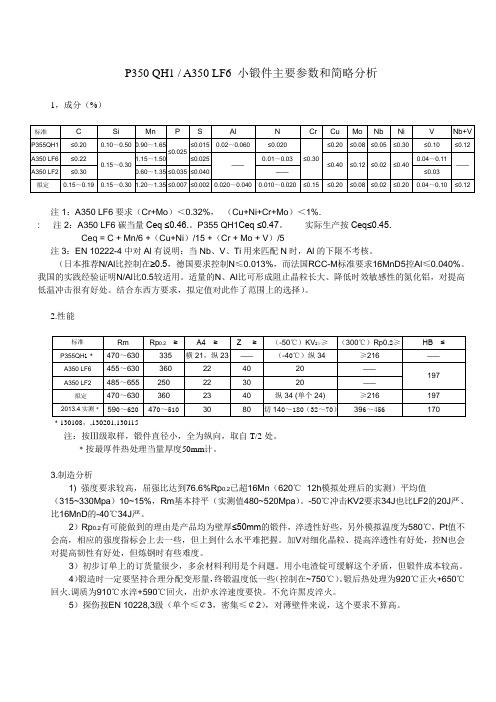
P350 QH1 / A350 LF6 小锻件主要参数和简略分析1,成分(%)注1:A350 LF6要求(Cr+Mo)<0.32%,(Cu+Ni+Cr+Mo)<1%.: 注2:A350 LF6碳当量Ceq ≤0.46.。
P355 QH1Ceq ≤0.47。
实际生产按Ceq≤0.45.Ceq = C + Mn/6 +(Cu+Ni)/15 +(Cr + Mo + V)/5注3:EN 10222-4中对Al有说明:当Nb、V、Ti用来匹配N时,Al的下限不考核。
(日本推荐N/Al比控制在≥0.5,德国要求控制N≤0.013%,而法国RCC-M标准要求16MnD5控Al≤0.040%。
我国的实践经验证明N/Al比0.5较适用。
适量的N、Al比可形成阻止晶粒长大、降低时效敏感性的氮化铝,对提高低温冲击很有好处。
结合东西方要求,拟定值对此作了范围上的选择)。
2.性能﹡130108,,130201,130115注:按Ⅲ级取样,锻件直径小,全为纵向,取自T/2处。
﹡按最厚件热处理当量厚度50mm计。
3.制造分析1) 强度要求较高,屈强比达到76.6%Rp0.2已超16Mn(620℃×12h模拟处理后的实测)平均值(315~330Mpa)10~15%,Rm基本持平(实测值480~520Mpa)。
-50℃冲击KV2要求34J也比LF2的20J严、比16MnD的-40℃34J严。
2)Rp0.2有可能做到的理由是产品均为壁厚≤50mm的锻件,淬透性好些,另外模拟温度为580℃,Pt值不会高,相应的强度指标会上去一些,但上到什么水平难把握。
加V对细化晶粒、提高淬透性有好处,控N也会对提高韧性有好处,但炼钢时有些难度。
3)初步订单上的订货量很少,多余材料利用是个问题。
用小电渣锭可缓解这个矛盾,但锻件成本较高。
4)锻造时一定要坚持合理分配变形量,终锻温度低一些(控制在~750℃)。
锻后热处理为920℃正火+650℃回火.调质为910℃水淬+590℃回火,出炉水淬速度要快。
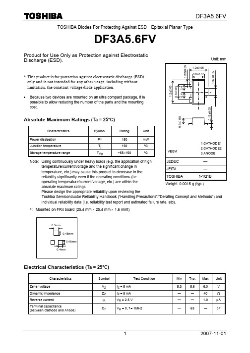
TOSHIBA Diodes For Protecting Against ESD Epitaxial Planar TypeDF3A5.6FVProduct for Use Only as Protection against Electrostatic Discharge (ESD).* This product is for protection against electrostatic discharge (ESD) only and is not intended for any other usage, including without limitation, the constant voltage diode application.• Because two devices are mounted on an ultra compact package, it ispossible to allow reducing the number of the parts and the mounting cost.Absolute Maximum Ratings (Ta = 25°C)Characteristics Symbol RatingUnitPower dissipation P *150 mWJunction temperature T j 150 °C Storage temperature rangeT stg−55~150 °CNote: Using continuously under heavy loads (e.g. the application of hightemperature/current/voltage and the significant change intemperature, etc.) may cause this product to decrease in thereliability significantly even if the operating conditions (i.e.operating temperature/current/voltage, etc.) are within theabsolute maximum ratings.Please design the appropriate reliability upon reviewing theToshiba Semiconductor Reliability Handbook (“Handling Precautions”/“Derating Concept and Methods”) and individual reliability data (i.e. reliability test report and estimated failure rate, etc). *: Mounted on FR4 board (25.4 mm × 25.4 mm × 1.6 mmt)Electrical Characteristics (Ta = 25°C)Characteristics Symbol Test Condition Min Typ. Max UnitZener voltage V Z I Z = 5 mA 5.3 5.66.0VDynamic impedance Z Z I Z = 5 mA ― ― 40 Ω Reverse currentI R V R = 2.5 V ―― 1.0 μATerminal capacitance(between Cathode and Anode)C TV R = 0, f = 1MHz― 65 ― pFUnit: mmWeight: 0.0015 g (typ.)Guaranteed Level of ESD ImmunityTest Condition ESD Immunity LevelIEC61000-4-2 (Contact discharge)± 30kVJudgment contents : No element destructionMarking Equivalent Circuit (top view)5.6RESTRICTIONS ON PRODUCT USE20070701-EN •The information contained herein is subject to change without notice.•TOSHIBA is continually working to improve the quality and reliability of its products. Nevertheless, semiconductor devices in general can malfunction or fail due to their inherent electrical sensitivity and vulnerability to physical stress. It is the responsibility of the buyer, when utilizing TOSHIBA products, to comply with the standards of safety in making a safe design for the entire system, and to avoid situations in which a malfunction or failure of such TOSHIBA products could cause loss of human life, bodily injury or damage to property.In developing your designs, please ensure that TOSHIBA products are used within specified operating ranges as set forth in the most recent TOSHIBA products specifications. Also, please keep in mind the precautions and conditions set forth in the “Handling Guide for Semiconductor Devices,” or “TOSHIBA Semiconductor Reliability Handbook” etc.• The TOSHIBA products listed in this document are intended for usage in general electronics applications (computer, personal equipment, office equipment, measuring equipment, industrial robotics, domestic appliances, etc.).These TOSHIBA products are neither intended nor warranted for usage in equipment that requires extraordinarily high quality and/or reliability or a malfunction or failure of which may cause loss of human life or bodily injury (“Unintended Usage”). Unintended Usage include atomic energy control instruments, airplane or spaceship instruments, transportation instruments, traffic signal instruments, combustion control instruments, medical instruments, all types of safety devices, etc.. Unintended Usage of TOSHIBA products listed in his document shall be made at the customer’s own risk.•The products described in this document shall not be used or embedded to any downstream products of which manufacture, use and/or sale are prohibited under any applicable laws and regulations.• Please contact your sales representative for product-by-product details in this document regarding RoHS compatibility. Please use these products in this document in compliance with all applicable laws and regulations that regulate the inclusion or use of controlled substances. Toshiba assumes no liability for damage or losses occurring as a result of noncompliance with applicable laws and regulations.。


© 2016 Littelfuse, Inc.Specifications are subject to change without notice. DescriptionThe Nano 2® SMF Fuse is a very small, Wire-in-Air (WIA) square shape surface mount fuse that was designed for secondary side circuit over-current protection applications. These fuses are designed for PCB using surface mount technology.Agency ApprovalsElectrical Characteristics for SeriesFeatures• Very fast-acting • Small size• Wide range of current rating available (0.062A to 20A)• Wide operating temperature range • Low temperature rerating • RoHS compliant and Halogen FreeApplications • Notebook PC • LCD/PDP TV • LCD monitor • LCD/PDP panel • LCD backlight inverter• Portable DVD player • Power supply • Networking • PC server• Cooling fan system• Storage system • Telecom system • Wireless basestation • White goods • Game console • Office Automation equipment • Battery charging circuit protection • Industrial equipmentSpecifications are subject to change without notice. Application testing is strongly recommended.Electrical Specifications by ItemNotes:- l2t calculated at 8ms.- Resistance is measured at 10% of rated current, 25ºC© 2016 Littelfuse, Inc.Specifications are subject to change without notice.Soldering Parameters© 2016 Littelfuse, Inc.Specifications are subject to change without notice.© 2016 Littelfuse, Inc.Specifications are subject to change without notice.Product CharacteristicsDimensionsPackagingPart Numbering System(.077")(.106")Recommended pad layout0451 001. M R LSERIESAMP CodeQUANTITY CodePACKAGING CodeRefer to Electrical characteristics table M = 1000 pcs N = 5000 pcsR = Tape and ReelL -RoHS Compliant & Halogen Free (Gold Plated Caps)451 = Gold / SnPb / Silver Plated Caps 453 = Silver Plated Caps NOTE: “L ” suffix applies to 451 series only- 451 series may be ordered as either “RoHS and HF” (“L ” suffix) or non-RoHS (no suffix) version.- 453 series is available only as RoHS compliant version and does not require “L ” suffix. Please do not include “L ” suffix within 453 series ordering instructions.SN-RoHS Compliant & Halogen Free (Sn-dipped Caps)。
DF简介滤波器的过去现在和未来滤波器的发展历程凡是有能⼒进⾏信号处理的装置都可以称为滤波器。
在近代电信设备和各类控制系统中,滤波器应⽤极为⼴泛;在所有的电⼦部件中,使⽤最多,技术最为复杂的要算滤波器了。
滤波器的优劣直接决定产品的优劣,所以,对滤波器的研究和⽣产历来为各国所重视。
1917年美国和德国科学家分别发明了LC滤波器,次年导致了美国第⼀个多路复⽤系统的出现。
20世纪50年代⽆源滤波器⽇趋成熟。
⾃60年代起由于计算机技术、集成⼯艺和材料⼯业的发展,滤波器发展上了⼀个新台阶,并且朝着低功耗、⾼精度、⼩体积、多功能、稳定可靠和价廉⽅向努⼒,其中⼩体积、多功能、⾼精度、稳定可靠成为70年代以后的主攻⽅向。
导致RC 有源滤波器、数字滤波器、开关电容滤波器和电荷转移器等各种滤波器的飞速发展,到70年代后期,上述⼏种滤波器的单⽚集成已被研制出来并得到应⽤。
80年代,致⼒于各类新型滤波器的研究,努⼒提⾼性能并逐渐扩⼤应⽤范围。
90年代⾄现在主要致⼒于把各类滤波器应⽤于各类产品的开发和研制。
当然,对滤波器本⾝的研究仍在不断进⾏。
我国⼴泛使⽤滤波器是50年代后期的事,当时主要⽤于话路滤波和报路滤波。
经过半个世纪的发展,我国滤波器在研制、⽣产和应⽤等⽅⾯已纳⼊国际发展步伐,但由于缺少专门研制机构,集成⼯艺和材料⼯业跟不上来,使得我国许多新型滤波器的研制应⽤与国际发展有⼀段距离。
滤波器的分类滤波器有各种不同的分类,⼀般有如下⼏种。
(1)按处理信号类型分类按处理信号类型分类,可分为模拟滤波器和离散滤波器两⼤类。
其中模拟滤波器⼜可分为有源、⽆源、异类三个分类;离散滤波器⼜可分为数字、取样模拟、混合三个分类。
当然,每个分类⼜可继续分下去,总之,它们的分类可以形成⼀个树形结构,如图所⽰。
实际上有些滤波器很难归于哪⼀类,例如开关电容滤波器既可属于取样模拟滤波器,⼜可属于混合滤波器,还可属于有源滤波器。
因此,我们不必苛求这种“精确”分类,只是让⼈们了解滤波器的⼤体类型,有个总体概念就⾏了。
威索燃烧器中文说明书(总43页)-CAL-FENGHAI.-(YICAI)-Company One1-CAL-本页仅作为文档封面,使用请直接删除安装使用说明书威索燃气燃烧器1-11号- weishaupt -证明在此我们说明,威索(-weishaupt-)燃气燃烧器符合下列EC标准的基本要求:90/396/EEC Gas Equipment Guideline89/336/EWG Electromagnetic Compatibility73/23/EEC Low Voltage Guideline因此燃烧器上带有CE/0085标记。
其它质量保证体系由DIN EN ISO 9001认可。
德国麦克斯·威索有限公司目录1. 一般说明.................................................................. 错误!未指定书签。
2. 燃烧器的安装.............................................................. 错误!未指定书签。
3. 气路示意图................................................................ 错误!未指定书签。
4. 阀门组件说明.............................................................. 错误!未指定书签。
5. 阀门组件的安装............................................................ 错误!未指定书签。
6. 阀门组件的气密性检验...................................................... 错误!未定义书签。
7. 功能流程检验.............................................................. 错误!未指定书签。
LF355/356/357 JFET输入型运算放大器——中文数据手册--by LF邮箱:fxfjy89123@整体描述:这些是第一个合成的JFET输入的运算放大器,它把匹配的高电压的JFET晶体管和标准的双极性晶体管放到了一块芯片上(双极FET技术)。
这些运放的特征是低输入失调和偏置电流、低偏置电压和偏置电压漂移、可以进行偏置调节而不会降低漂移和共模抑制比。
这些运放也设计有高压摆率、宽带宽、极快的建立时间、低电压电流噪声。
特征:优点--代替昂贵的混合型和模块型FET运算放大器--低噪声应用性能优异——高或低的输入源阻抗均可--偏置可调不会像其他合成型运放降低漂移和共模抑制比--新的输出阶段可以接入大的电容负载(5000pF)不会出现稳定性问题--内部补偿和可承受大的差分输入电压应用:--精密高速积分器--快速模/数和数/模转换器--高阻抗缓冲保护--宽带、低噪、低漂移放大器--对数放大器--光电放大器--采样保持电路共同特性:--低输入失调电流——30pA--低输入偏置电流——3pA--高输入阻抗——10的12次方Ω--低输入噪声电流——0.01pA/sqrt(Hz)--高共模抑制比——100dB--高直流增益——106dB不同特性:--极快的建立时间——5系列4us,6系列7系列1.5us--快速的压摆率——5系列5V/us,6系列12V/us,7系列50V/us--宽增益带宽——5系列2.5MHz,6系列5MHz,7系列20MHz--低输入噪声电压——5系列20nV/sqrt(Hz),6系列7系列12nV/sqrt(Hz)供电电压:±15V典型电路连接:Vos调节--Vos用一个25k的电位器调节--电位器中间调节端连到V+驱动容性负载--对于LF155/6 R=5k--对于LF357 R=1.25k--由于独特的输出平台设计,这些放大器能够驱动大的容性负载并且能保持稳定性。
Cl(MAX)≈0.01uF--建立时间(Ts)≈5us大功率带宽放大器--小于等于1%的失真度,20V峰峰值的输出抖动,功率带宽为500kHz建立时间测试电路--LF155/6连接成单位增益变频器来测试建立时间,LF357连接使得Av=-5--FET用来隔离探头的电容--输出10V步进--对于LF357来说Av = -5宽带低噪低漂移放大器--寄生输入电容C1≈(LF355是3pF,LF356和LF357要加上额外的布局电容)和反馈因素相互作用产生高频极点。
DF005 – DF101.0A GLASS PASSIVATED BRIDGE RECTIFIERSingle Phase, half wave, 60Hz, resistive or inductive load.For capacitive load, derate current by 20%.Characteristic Symbol DF005DF01DF02DF04DF06DF08DF10UnitPeak Repetitive Reverse Voltage Working Peak Reverse Voltage DC Blocking Voltage V RRMV RWMV R501002004006008001000VRMS Reverse Voltage V R(RMS)3570140280420560700V Average Rectified Output Current @T A = 40°C I O 1.0A Non-Repetitive Peak Forward Surge Current 8.3msSingle half sine-wave superimposed on rated load(JEDEC Method)I FSM30A Forward Voltage per element @I F = 1.0A V FM 1.1VPeak Reverse Current @T A = 25°C At Rated DC Blocking Voltage @T A = 125°C I RM10500µATypical Junction Capacitance per element (Note 1)C j25pF Typical Thermal Resistance (Note 2)R JA40K/W Operating and Storage Temperature Range T j, T STG-55 to +150°CNote: 1. Measured at 1.0 MHz and applied reverse voltage of 4.0V D.C.2. Thermal resistance junction to ambient mounted on PC board with 13mm2 copper pad.WTE0.010.11.0100.40.60.81.01.21.4I ,I N S T A N T A N E O U S F O R W A R D C U R R E N T (A )F V ,INSTANTANEOUS FORWARD VOLTAGE (V)Fig.2T yp Forward Characteristics (per element)F 0102030405060110100I ,P E A K F O R W A R D S U R G E C U R R E N T (A )F S M NUMBER OF CYCLES AT 60 HzFig. 3 Max Non-Repetitive Peak Forward Surge Current110100110100C ,C A P A C I T A N C E (p F )J V ,REVERSE VOLTAGE (V)Fig.4Typ Junction Capacitance (per element)R 0.010.11.01010020406080100120140I ,I N S T A N T A N E O U S R E V E R S E C U R R E N T (µA )R PERCENT OF RATED PEAK REVERSE VOLTAGE (%)Fig.5Typ Reverse Characteristics (per element)1.00.5406080100120140I ,A V E R A G E F O R W A R D C U R R E N T (A )(A V )T ,AMBIENT TEMPERATURE (°C)Fig.1Output Current Derating Curve AORDERING INFORMATIONProduct No.Package TypeShipping QuantityDF005DIL Bridge 50 Units/Tube DF01DIL Bridge 50 Units/Tube DF02DIL Bridge 50 Units/Tube DF04DIL Bridge 50 Units/Tube DF06DIL Bridge 50 Units/Tube DF08DIL Bridge 50 Units/Tube DF10DIL Bridge50 Units/TubeShipping quantity given is for minimum packing quantity only. For minimum order quantity, please consult the Sales Department.Won-Top Electronics Co., Ltd (WTE) has checked all information carefully and believes it to be correct and accurate. However, WTE cannot assume any responsibility for inaccuracies. Furthermore, this information does not give the purchaser of semiconductor devices any license under patent rights to manufacturer. WTE reserves the right to change any or all information herein without further notice.WARNING : DO NOT USE IN LIFE SUPPORT EQUIPMENT. WTE power semiconductor products are not authorized for use as critical components in life support devices or systems without the express written approval.We power your everyday.Won-Top Electronics Co., Ltd.No. 44 Yu Kang North 3rd Road, Chine Chen Dist., Kaohsiung, Taiwan Phone: 886-7-822-5408 or 886-7-822-5410Fax: 886-7-822-5417Email: sales@Internet: 。
TOSHIBA Diodes for Protecting against ESD Epitaxial Planar TypeDF3A5.6LFVProduct for Use Only as Protection against Electrostatic Discharge (ESD).* This product is for protection against electrostatic discharge (ESD) only and is not intended for any other usage, including without limitation, the constant voltage diode application.• The mounting of two devices in an ultra-compact package enables areduction in the number of parts and in the mounting cost. • Low terminal capacitance: C T = 8.0 pF (typ.)Absolute Maximum Ratings (Ta = 25°C)Characteristic Symbol RatingUnit Power dissipation P150* mWJunction temperature T j 150°C Storage temperature rangeT stg−55~150 °CNote: Using continuously under heavy loads (e.g. the application of high temperature/current/voltage and the significant change intemperature, etc.) may cause this product to decrease in thereliability significantly even if the operating conditions (i.e. operating temperature/current/voltage, etc.) are within theabsolute maximum ratings.Please design the appropriate reliability upon reviewing theToshiba Semiconductor Reliability Handbook (“Handling Precautions”/“Derating Concept and Methods”) and individual reliability data (i.e. reliability test report and estimated failure rate, etc). *: Mounted on an FR4 board (25.4 mm × 25.4 mm × 1.6 mmt)Electrical Characteristics (Ta = 25°C)Characteristic Symbol Test ConditionMin Typ. Max Unit Zener voltage V Z I Z = 5 mA 5.35.66.0V Dynamic impedance Z Z I Z = 5 mA ⎯ 3 ⎯ Ω Reverse currentI R V R = 3.5 V ⎯⎯1.0μATerminal capacitance(between cathode and anode)C TV R = 0 V, f = 1 MHz― 8 ― pFUnit: mmWeight: 1.5 mg (typ.)Guaranteed Level of ESD ImmunityTest Condition ESD Immunity LevelIEC61000-4-2 (Contact discharge)± 8 kVCriterion: No damage to device elementsMarking Equivalent Circuit (top view)6 4 1 μZENER VOLTAGE VZ (V)I Z – V ZZ E N E R C U R R E N T I Z (m A )REVERSE VOLTAGE VR (V)5 76 C T – V R3 T O T A L C A P A C I T A N C E C T (p F )AURESTRICTIONS ON PRODUCT USE20070701-EN •The information contained herein is subject to change without notice.•TOSHIBA is continually working to improve the quality and reliability of its products. Nevertheless, semiconductor devices in general can malfunction or fail due to their inherent electrical sensitivity and vulnerability to physical stress. It is the responsibility of the buyer, when utilizing TOSHIBA products, to comply with the standards of safety in making a safe design for the entire system, and to avoid situations in which a malfunction or failure of such TOSHIBA products could cause loss of human life, bodily injury or damage to property.In developing your designs, please ensure that TOSHIBA products are used within specified operating ranges as set forth in the most recent TOSHIBA products specifications. Also, please keep in mind the precautions and conditions set forth in the “Handling Guide for Semiconductor Devices,” or “TOSHIBA Semiconductor Reliability Handbook” etc.• The TOSHIBA products listed in this document are intended for usage in general electronics applications (computer, personal equipment, office equipment, measuring equipment, industrial robotics, domestic appliances, etc.).These TOSHIBA products are neither intended nor warranted for usage in equipment that requires extraordinarily high quality and/or reliability or a malfunction or failure of which may cause loss of human life or bodily injury (“Unintended Usage”). Unintended Usage include atomic energy control instruments, airplane or spaceship instruments, transportation instruments, traffic signal instruments, combustion control instruments, medical instruments, all types of safety devices, etc.. Unintended Usage of TOSHIBA products listed in his document shall be made at the customer’s own risk.•The products described in this document shall not be used or embedded to any downstream products of which manufacture, use and/or sale are prohibited under any applicable laws and regulations.• Please contact your sales representative for product-by-product details in this document regarding RoHS compatibility. Please use these products in this document in compliance with all applicable laws and regulations that regulate the inclusion or use of controlled substances. Toshiba assumes no liability for damage or losses occurring as a result of noncompliance with applicable laws and regulations.。