SMC数字压力开关接线
- 格式:doc
- 大小:397.46 KB
- 文档页数:3
smc3C-S3000-02气动式压力开关说明书smc3C-S3000-02气动式压力开关主要类别包括常开式和常闭式。
主要特点是:
1、采用英制管螺纹快速接头或铜管焊接式安装结构,安装灵活,使用方便,无需特殊的安装固定。
2、插片式导线式连接方可供用户任意选定。
3、密封式不锈钢感应器安全可靠。
4、压力范围内可根据用户任意选定的压力值进行制造。
smc3C-S3000-02气动式压力开关的使用事项:
一:使用环境
1:适合流体:空气、非腐蚀性气体;
2:使用温度:保存时0~50℃,工作时10~50℃。
开关有滞后
功能,通电2秒后显示;
3:供应电源:DC12~24V±10%,最大负载电流80mA;
4:消耗电流:55mA或以下;
5:安装方式:面板安装+保护盖;
6:防止强烈震荡,被用于有水或灰尘的地方,要用导管把重温
端口引到安全位置。
二:输出信号:
1:五芯电线,棕色“+”,蓝色“-”,黒色:OUT1,白色:OUT2,灰色:模似信号线。
2:NPN集电极开路输出,红绿两种信号,OUT1输出时绿灯亮,OUT2输出时红亮。
3:采用31/2位数LED数字显示。
三:规格型号规格型号设定压力范围输出设置ZSE40(真空压)10.00~-101.3KPa NO:常闭,NC:常开ZSE40F(混合压)-100.0~100.0KPa NO:常开,NC:常闭ISE40(正压)-0.100~1.000MPaNO:常开,NC:常闭。
Digital Flow Switch (Display Part) Operation Manual For AirPF2A300/301 SeriesPF2A310/311 SeriesFor Pure Water/Chemical Fluid PF2D300/301 SeriesFor WaterPF2W300/301 SeriesPF2W330/331 SeriesURL SAFETY2Model Indication Method4Name and Functions of Individual Parts 6Installation7Outline with Dimensions8Example of Internal Circuit and Wiring 9Setting 10Initialize11Display Function of Integrated Flow Rate Value 15Instantaneous Flow Rate Setting Mode16Integrated Flow Rate Setting Mode 19Output Selection 20Other Functions 23Specification24CONTENTSThank you for purchasing the SMC PF2*3**Series Digital Flow Switch.Please read this manual carefully before operating digital flow switch and understand digital flow switch, its capabilities and limitations.Please keep this manual handy for future reference.OPERATOR•This operation manual has been written for those who have knowledge of machinery and apparatus that use pneumatic equipment and have full knowledge of assembly, operation and maintenance of such equipment.•Please read this operation manual carefully and understand it before assembling, operating or providing maintenance service to the flow switch.32NOTEFollow the instructions given below when handling your flow switch.Otherwise, the switch may be damaged or may fail, thereby resulting in malfunction.•Do not drop it, bring it into collision with other objects or apply excessive shock (490m/s 2or more).•Wiring correctly.•Do not wiring while power is on.•Although the flow switch complies with the CE Marking, since it does not have the thunder serge protection, please carry out protection to thunder serge by the equipment side.•Although the flow switch complies with the CE Marking, since the equipment and apparatus which are made to generate the serge (Electro-magnetic lifter, High frequency induction furnace, Motor etc.) around the flow switch should perform measure against serge come out.•Do not use with power cable or high-voltage cable in the same wire route.•Do not use in a place in which water, oil, or a chemical splashes.•Do not push the setting buttons by a sharply pointed object.•Turn on the power supply of a flow switch for Air, when flow is zero.Some initial drift occurs during ten minutes after turning the power on.•Start measurement by the flow switch three seconds after turning on the power. (Also in momentary interception of the power supply by reset etc.) Please take a measure by the program of equipment etc.•Maintain the switch status for measurement output before setting when initializing or setting a flow rate of the flow switch.Measure after checking impacts to the equipment.Carry out a setup since a control system is shut down if required.The Digital Flow Switch and this manual contain essentialinformation for the protection of users and others from possible injury and property damage and to ensure correct handling.Please check that you fully understand the definition of the following messages (signs)before going on to read the text, and always follow the instructions.Please read the operation manuals of related apparatus and understand it before operating the flow switch.Do not disassemble, remodel (including change of printed circuit board) or repair.An injury or failure can result.Do not operate beyond specification range.Fire, malfunction or switch damage can result.Please use it after confirming the specification.Do not operate in atmosphere of an inflammable, an explosive and corrosive gas.Fire or an explosion can result.This flow switch is not an explosion-proof type.54NOTE 1:The new Measurement Low prohibits use in Japan of flowswitches with a unit selection function.NOTE 2:Fixed unit for instantaneous flow rate is :L/minfor integrated flow rate is :LSeparate Type Display PartA : AirD : Pure Water/Chemical Fluid W : Water•About sensor partThe type of the sensor part combined with a display part is indicated to be PF *5**with this manual.Refer to the following correspondence table for the sensor part type combined with each display part.BodyOutput (OUT1) Lamp (Green):Lit when OUT1 is ON. Flickers when an overcurrent erroroccurs.Output (OUT2) Lamp (Red):Lit when OUT2 is ON. Flickers when an overcurrent erroroccurs.LED Display:Displays a flow rate, set mode status, selected display unitand error code.Button (UP): Selects a mode and increases a set ON/OFF value.Button (DOWN): Selects a mode and decreases a set ON/OFFvalue.Button (SET): Changes the mode and sets a set value. RESETPressing the and buttons simultaneously will activate the RESET function.Use this function to clear errors when a trouble occurs.Panel Mount Adapter type ZS-22-EPanel Mount Adapter APanel Mount Adapter BBracket are includedMounting•Install the Display Part on the panel, once the Panel Mount Adaptor Bremoves.•Insert Panel Mount Adapter B supplied as an accessory intoSection A of Panel Mount Adapter A.Push Panel Mount Adapter B from behind till the display is fixedonto the panel.The pin of Panel Mount Adapter B engages the notched part ofPanel Adapter A to fix the display.•The switch can be mounted on a panel with a thickness of 1.0 to3.2mm.•See the illustration below for panel cut dimensions.Panel Cut Dimensions Accessories LED DisplayLamp (Red)SETButton (UP)7 698++0.5Panel Thickness: 1 to 3.2mmPanel Cut DimensionsOutput SpecificationBe sure to select a sensor in SMC PF *5**series for accurate measurement of flow rates.The display outputs only switch output.Analog output is output directly by the sensor part. See theoperation manual of the sensor part for the complete information. Connection•Turn the power off before making connection.•Install the cable separately from the route for power cable or high-voltage cable. Otherwise, malfunction may potentially result due to noise.•Use compression terminals for connection to the terminal board.See the full view of dimensions diagram for details of the terminal board.–0NPN Open Collector Output 2OutputsMax. 30V, 80mAInternal Voltage Drop 1V or less–1PNP Open Collector Output 2Outputs Max 80mAInternal Voltage Drop 1.5V or lessPF ∗5 SeriesPF ∗5 SeriesSetting ProceduresKeep pressing the button longer than two seconds. Remove the finger off the button when one of the characters of LED display column of the following table is displayed.1. Flow Rate Range SettingPress the button and select the flow rate range.Press thebutton to set.2. Display Mode SettingSelect whether to display instantaneous flow rate orintegrated flow rate.To change the Display mode, press thedesired flow rate to display. Then press the button.[d_1] and [d_2] respectively indicate the instantaneous flow rate and integrating flow rate.11103. Selecting Display Unit(In case [-M] is not assigned to unit specification in model indication) Refer to page 14.4. Output Method SettingThree output methods are available, namely, instantaneous switch, integrating switch and integrating pulse. The method for output to OUT1 or OUT2 is set as follows.1)First, the output method for OUT1 is set.*Press the button and select the instantaneous switch,integrating switch or integrating pulse.*Press the button to set.[o10] [o11] and [o12] respectively indicate the2)Select one output method for OUT2 from three output methods by pressing the button, as in OUT1.*Press the button to set.[o20] [o21] and [o22] respectively indicate theinstantaneous switch, integrating switch and integrating pulse.5. Output Mode SettingTwo output modes are available, namely, the Reverse Output modeand Non-Reverse Output mode. An output mode for OUT1 andOUT2 is set.1)First, the output method for OUT1 is set.*Press the button and select the Reverse Output mode or Non-Reverse Output mode.*Press the button to set.[1_n] and [1_P] respectively indicate the Reverse Outputmode and Non-Reverse Output mode.mode and Non-Reverse Output mode by pressing the button,as in OUT1.*Press the button to set.[2_n] and [2_P] respectively indicate the Reverse Outputmode and Non-Reverse Output mode.13 1215•Press the button first, then the button, to press both buttons simultaneously. Integration starts when [–] flickers.•Lower three digits of an integrated value are always displayed.Press the button when wishing to check upper three digits.•Pressing the button enables to display an instantaneous flow rate even during integration.•To stop integration, press the button first, then the button,to press both buttons simultaneously.The display will keep the present integrated value.To clear display of an integrated value, press both the and buttons simultaneously longer than two seconds.To further continue integration from the saved value, repress thebutton first, then the button, to press both buttons simultaneously.1716Manually set an actuation value of the instantaneous-value switch in case the instantaneous switch is selected in initialization.The output method is also set in accordance with the value set manually. Set the output method while referring to the output method described below.1.Keep pressing the button and remove the finger off when [F-1] is displayed.2.Repress the button to set for input of a set value in [n_1] (P_1 in the Non-Reverse Output mode) for OUT1.In case the Reverse Output mode is selected in initialization, [n_1]and the set value will be displayed alternately.(In case the Non-Reverse Output mode is selected in initialization,[P_1] and the set value will be displayed alternately.) 3.Press the or buttons to select a desired set value.Press the button to increase the set value or the button to decrease the set value.4.Press the button to set the set value and to move to the setting mode for [n_2] (P_2 in the Non-Reverse Output mode).In case the Reverse Output mode is selected in initialization, [n_2]and the set value will be displayed alternately.(In case the Non-Reverse Output mode is selected in initialization,[P_2] and the set value will be displayed alternately.) 5.Press the or buttons to select a desired set value.Press the button to increase the set value or the button todecrease the set value.6.Press the button to set the set value and to move to the setting mode for OUT2.Set the set value as in OUT1.In case the Reverse Output mode is selected for the OUT2 setting in initialization, [n_3] or [n_4] and the set value will be displayed alternately.In case the Non-Reverse Output mode is selected in initialization,[P_3] or [P_4] and the set value will be displayed pleting settings for [n_1] to [n_4] ([P_1] to [P_4] in the Non-Reverse Output mode) will finish flow rate setting and the mode will return to the Measurement mode.Manual1918The flow rate flowing through the flow switch will be set as areference value and a Hysteresis (H) will be set automatically at a value 3digits lower when setting auto preset input.The output method for setting by auto presetting is only hysteresis mode.1.Keep pressing the button and remove the finger off when [F_1] is displayed.2.Press the button and change [F_1] in the display to [F_2].3.Press the button and set the auto preset state of OUT1.The display will change to show [AP1] .(In case OUT1 setting is not needed, press the and button simultaneously.)4.Prepare the equipment to set the flow rate of OUT1 and flow fluid of the required flow rate.5.Pressing the button will automatically read the flow rate. A value 3digits lower will be set automatically as a Hysteresis (H).The display will show [A1L] and the set value alternately.6.Press the button and set auto preset state of OUT2.The display will change to show [AP2].(In case OUT2 setting is not needed, press the and buttons simultaneously.)7.Prepare the equipment to set the flow rate of OUT2 and flow fluid of the required flow rate.8.Pressing the button will automatically read the flow rate. A value 3digits lower will be set automatically as a Hysteresis (H).The display will show [A2L] and the set value alternately.9.Press the button to finish the Auto Presetting mode and themode will return to the Measurement mode.Auto Presetting•The switch is set to an integrated flow rate.•Integrated flow rate is displayed by switchingdividing into lower three digits and upper three digits. 1.Keep pressing the button and remove the finger off when [F_1] or [F_3] is displayed.Proceed to Step 3. if [F_3] is displayed.([F_1] will be displayed in case the instantaneous switch is selected for any switch output in initialization. In other cases,[F_3] will be displayed.)2.When [F_1] is displayed, push the button till the display shows [F_3]. The subsequent setting operation will be the same as that when [F_3] is displayed. Set as follows.3.Set as follows if [F_3] is displayed.1)Press the button and display the lower three digits of the integrated flow rate of OUT1.2)Press the or buttons and adjust the set value to the desired value.3)Press the button to set. The upper three digits of OUT1 will be displayed.4)Press the or buttons and adjust the set value to the desired value.5)Press the button to set. The lower three digits of OUT2 will be displayed.6)Press the or buttons and adjust the set value to the desired value.7)Press the button to set. The upper three digits of OUT2 will be displayed.8)Press the or buttons and adjust the set value to the desired value.9)Press the button to finish setting of an integrated flow rate and the mode will return to the Measurement mode.Instantaneous Switch Output MethodFour output methods can be selected by selecting an output modeOne of these four output methods can be selected for each output.•OUT1 and OUT2 can be set independently.•1digit flow rate conversion will be a minimum set unit. See thespecification for the set flow rate units.•When setting in the Auto Presetting mode, the Hysteresis mode willbe set automatically. Hysteresis in this case will be 3digits fixed.•In the Window Comparator mode, leave between [P_1] and [P_2]or between [n_1] and [n_2] values more than seven digits.•The following is given using OUT1 as an example. Thedescriptions for OUT2 are the same as those for OUT1, under theconditions that [n_1] and [n_2] should be replaced by [n_3] and[n_4] and [P_1] and [P_2] should be replaced by [P_3] and [P_4].20212322To reset display of Error 1, 2 or 4, press theandbuttons simultaneously.Integrating Switch Output•Two output methods can be selected by selecting an output mode.One of these two output methods can be selected for each output.•OUT1 and OUT2 can be set independently.•The following is given using OUT1 as an example. Thedescriptions for OUT2 are the same as those for OUT1, under the conditions that 1nL and 1nH should be replaced by 2nL and 2nH and 1PL and 1PH should be replaced by 2PL and 2PH.Integrating Pulse Output•Pulse output for integrated flow rate measurement.Key Lock FunctionThis function prevents errors such as changing a set value by mistake.Lock•Keep pressing the button longer than three seconds.The display will change to show [F_1] Æ[***] Æ[unL.]Remove the finger off the button when [unL] is displayed.([***]:Refer to the LED display column in the table, Page11)•Press the button to set the display to [Loc]•Press the button and return to the Measurement mode.Unlock •Press the button longer than three seconds. Remove the finger off the button when [Loc] is displayed.•Press the button to change the display to [unL]•Press the button and return to the Measurement mode.Error Display and TroubleshootingIn case an error occurs, take the following actions:2524*1:The flow rate indication range is corresponding to the flow rate range set up bythe initialization.*2:With a unit selection function(Without a unit selection function, fixed to SI units(L/min or L))*3:Two units in normal condition (0˚C/ 101.3kPa) or standard condition (20˚C/101.3kPa/ 65%RH) can be selected.*4:This is an overall accuracy combined with PF2A 5**.*5:Select whether to switch output or pulse output of integrated flow rate by theinitialization.*6:Window Comparator mode. Hysteresis (H) will be in 3digits.Separate [P_1] and [P_2], as well as [n_1] and [n_2], more than 7digits.(In case of the output 2, n_1,2 becomes n_3,4 and P_1,2 becomes P_3,4)*7:The display part conforms entirely to the CE standard.2627。
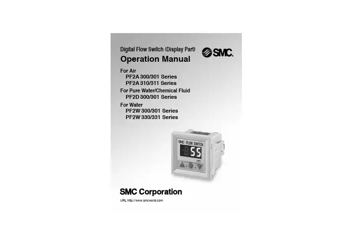
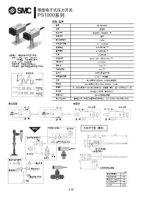
smc数显压⼒表设定⽅法_⽇本SMC数显压⼒表中⽂说明书ISE40A-01-P-ML⽇本SMC数显压⼒表中⽂说明书ISE40A-01-P-ML特点:●IP65●适合流体: 空⽓, ⾮腐蚀性⽓体, ⾮燃性⽓体●多可同时拷贝⾄10台●3步设定●带快换接头配管规格 01 R1/8(带M5内螺纹)输出规格 P PNP开路集电极1输出单位规格 M SI单位固定可选项1 - ⽆可选项2 - 使⽤说明书:-;校正证明书:空⽓,⾮腐蚀性⽓体,不可燃⽓体12⾄24 VDC o 10%,纹波(pp)10%或更低(带电源极性保护)45 mA或更低NPN或PNP开路集电极1输出或2输出80毫安28 V(NPN输出)1 V或更低2.5 ms(具有防抖功能:20,100,500,1000,2000 ms)是的o 0.2%F.S。
o 1位数变量(0或以上)注1设定压⼒范围是设定时可能的压⼒范围。
满⾜开关规格(精度,线性度等)的压⼒范围的额定压⼒范围。
虽然可以设定超出额定压⼒范围的值,但即使值保持在规定范围内,也不能保证规格设定的压⼒范围。
当压⼒开关⽤于⽔和灰尘飞溅的地⽅时可能会发⽣,将管插⼊⼤⽓通风⼝,并将另⼀根管路径管的末端到⼀个安全的地⽅,远离⽔和灰尘。
SMC TU 0425(聚氨酯,O.D。
?4,I.D.?2.5)适合压⼒开关。
KPQL06-M5KSL04-M5KSH06-01SSY5420-5DZ-01 24DCVF5210-5DZ-03CKZT50-105T-DCK9412K CKZT50-105T-DCK9413K KQ2R06-10AMY1B80ZH10BKQ2E12-04PF2W720-F04-27(NPN) TS0806BU-20 20⽶/卷KQ2H16-00AKQGH08-03SMDBB63-200AW40-03H-X2050AW30-03E-RVT317E-5DZ-02AW30-F03ISE40A-01-P-MLEVS7-6-FG-D-3CVO-QC96 SDB 63-100-M9 PW KQ2L16-04ASKQ2H16-04ASKQ2U16-00AG27-20-01BBS6-4KK130P-01MSKK130S-01MSISE40A-C6-T-X501CK1B50-50YZCK1B63-50YZCK1B63-75YZCK1B63-100YZCK1B63-125YZCKZP40-40-DCK048JKMGPL40-50-X986MGPA50-50-X986VBA10A-02VVQC2000-3A-1-C10-SVVQC2000-1A-D-C8VVQC2000-2A-1-C10-SKQGH10-02SKQGS10-02SKQGH08-01SKQGS08-01SMGPL80-75-X986MGZL32Z-75-M9PWVAN700-12(11/4')MBD50-100MBD63-150CM2B32-25ACDQ2B63-50DZ-P3DWSECDQ2B63-50DCMZ-P3DWSCMBT80TF-75ZCQ2A63-25DCMZ-XC35CQ2A50-50DCMZ-XC35C96SB63-25-XC35C96SB63-50-XC35C96SB63-160-XC35CDQ2B40-30DCMMGPL40-25Z-M9BWSDPC-XC35CDQ2B40-35DCMZ-M9BWSDPC-XC35⽇本SMC数显压⼒表中⽂说明书ISE40A-01-P-ML。
文件No.PS※※-OMM0006-A 使用说明书产 品 名 称数字式压力开关型式/系列/型号ZSE40A(F)ISE40A目录安全注意事项 2 型式表示・型号体系 9 产品各部品名称及功能 11 用语的定义及用语集 12 安装・设置 15 设置方法 15 配管方法 17 配线方法 19 压力设定 21 什么是设定模式 21 功能设定 23 什么是功能选择模式 23 出厂设定 23 F0 单位切换功能 25 F1 OUT1的设定 26 F2 OUT2的设定 29 F3 响应时间的设定 31 F4 自动预设功能的设定 32 F5 模拟输出/自动移位输入的设定 34 F6 显示值微调整的设定 36 F11 分辨率的设定 37 F80 省电模式的设定 38 F81密码输入的设定 39 特殊功能的设定 40 F90 全功能的设定 40 F97 复制功能的选择 42 F98 输出确认 44 F99 恢复出厂设置 46 其他设定 47 维护 50 忘记密码的情况 51 故障的消除 52 规格 59 规格表 59 外形尺寸图 61安全注意事项这里所示的注意事项是为了能安全正确的使用本产品,预先防止对您和他人造成危害或损失。
为了表示这些事项的危险程度,将注意事项分成「注意」「警告」和「危险」三个等级。
请您也遵守和安全相关的其他重要内容,如国际规格(ISO/IEC)、日本工业规格(JIS)※1以及其他安全法规※2。
*1) ISO 4414: Pneumatic fluid power -- General rules relating to systemsISO 4413: Hydraulic fluid power -- General rules relating to systemsIEC 60204-1: Safety of machinery -- Electrical equipment of machines (Part 1: General requirements) ISO 10218-1: Robots for industrial environments—Safety requirements –Part 1: RobotJIS B 8370: 空气压系统通则JIS B 8361: 油压系统通则JIS B 9960-1: 机械类的安全性-机械的电气装置(第1部:一般要求事项)JIS B 8433-1: 工业机器人- 安全要求事项-第1部: 机器人等*2) 劳动安全卫生法 等注意: 错误操作时,人和设备可能受到损伤的事项。
产品名称:SMC流量计参数设置方法SMCCORPORATION成立于1959年,总部设在日本东京都。
时至今日,SMC已成为世界级的气动元件研发、制造、销售商。
在日本本土更拥有庞大的市场网络,为客户提供产品及售后服务。
SMC 作为世界最著名的气动元件制造和销售的跨国公司,其销售网及生产基地遍布世界。
SMC产品以其品种齐全、可靠性高、经济耐用、能满足众多领域不同用户的需求而闻名于世。
在日本市场占有率已超过60%的SMC,通过分布于世界51个国家的海外子公司及分销商,将世界各国SMC产品的生产、销售连成一体,为用户提供直接、完善的服务。
Other SettingsSummary of Product partsSimple Setting ModeTroubleshootingNote: Specifications are subject to change without prior notice and any obligation on the part of the manufacturer.© 2017 SMC Corporation All Rights ReservedAkihabara UDX 15F, 4-14-1, Sotokanda, Chiyoda-ku, Tokyo 101-0021, JAPANPhone: +81 3-5207-8249 Fax: +81 3-5298-5362URL Specifications/Outline with Dimensions (in mm)Refer to the product catalog or SMC website (URL ) for moreinformation about the product specifications and outline dimensions.PS※※-OMU0004 InstallationMountingMount the optional bracket and panel mount adapter to the pressure switch.When the pressure switch is to be mounted in a place where water and dustsplashes occur, insert a tube into the air-relieving port of the pressure switch.(Refer to "Tube attachment")Mounting with bracketMount the bracket to the body with mounting screws (Self tapping screws:Nominal size 3 x 8L (2 pcs)), then set the body to the specified position.∗: Tighten the bracket mounting screws to a torque of 0.5±0.05 Nm.Self tapping screws are used, and should not be re-used several times.∗: The panel mount adaptercan be rotated through 90degrees for mounting.•Bracket A (Part No.: ZS-46-A1)•Bracket B (Part No.: ZS-46-A2)Mounting with panel mount adapterMount part (a) to the front of the body and fix it. Then insert the body with (a) intothe panel until (a) comes into contact with the panel front surface. Next, mountpanel for fixing.•Panel mount adapter(Part No.: ZS-46-B)Panel mount adapter +Front protective cover(Part No.: ZS-46-D)WiringWiring connectionsUse a separate route for the product wiring and any power or high voltage wiring.Otherwise, malfunction may result due to noise.If a commercially available switching power supply is used, be sure to ground theframe ground (FG) terminal. If the switching power supply is connected for use,switching noise will be superimposed and it will not be able to meet the productspecifications. In that case, insert a noise filter such as a line noise filter/ferritebetween the switching power supplies or change the switching power supply tothe series power supply.How to use connectorConnector attachment/detachmentWhen connecting the connector, insert itstraight onto the pins, holding the lever andconnector body, and lock the connector bypushing the lever hook into the concavegroove on the housing.To detach the connector, remove the hookfrom the groove by pressing the leverdownward, and pull the connector straight out.DC(+)OUT1OUT2FUNCDC(-)BrownBlackWhiteGrayBluePipingTightening the connection threadFor connecting to the body (piping specification: -M5)After hand tightening, apply a spanner of the correct size tothe spanner flats of the piping body, and tighten with a 1/6 to1/4 rotation.As a reference, the tightening torque is 1 to 1.5 Nm.(When replacing the piping adapter ZS-46-N∗, tighten it usingthe same method.)Piping specification: -01, -N01After hand tightening, hold the hexagonal spanner flats of thepressure port with a spanner, and tighten with 2 to 3 rotations.As a reference, the tightening torque is 3 to 5 Nm.When tightening, do not hold the pressure switch body with aDefault settingsWhen the pressure exceeds the setvalue, the switch will be turned on.When the pressure falls below theset value by the amount ofhysteresis or more, the switch willbe turned off. The default setting isto turn on the pressure switch whenthe pressure reaches the centre ofthe atmospheric pressure and upper limit of the rated pressure range. If this condition,shown to the right, is acceptable, then keep these settings.Error indication functionThis function is to display error location and content when a problem or error has occurred.above are displayed, please contact SMC.Refer to the SMC website (URL ) for more information abouttroubleshooting.Power is supplied.button between1 and 3 sec.∗:The outputs will continue to operate during setting.∗:If a button operation is not performed for 3 seconds during the setting, the display will flash.(This is to prevent the setting from remaining incomplete if, for instance, an operator were to leave duringsetting.)∗:3 step setting mode, simple setting mode and function selection mode settings are reflected each other.[3 step setting mode (hysteresis mode)]orcan be changed in the same way.button once when the item to beThe set value on the sub display (right) will startflashing.orbutton.buttons are pressed and held simultaneously for 1 second orlonger, the set value is displayed as [- - -], and the set value will be the same as thecurrent pressure value automatically (snap shot function).Afterwards, it is possible to adjust the value by pressing button.button to complete the setting.The pressure switch turns on within a set pressure range (from P1L to P1H) duringwindow comparator mode.Set P1L, the lower limit of the switch operation, and P1H, the upper limit of the switchoperation and WH1 (hysteresis) following the instructions given above.(When reversed output is selected, the sub display (left) shows [n1L] and [n1H].)∗:Set OUT2 in the same way. (ex. P_2, H_2)∗:Setting of the normal/reverse output switching and hysteresis/window comparator mode switchingare performed with the function selection mode [F 1] OUT1 setting and [F 2] OUT2 setting.value[F 0] Units selection functionPeak/bottom value indicationbutton inmeasurement mode.Snap shot functionbuttons for 1 secondor longer simultaneously. Then, the set value of the sub display (right) shows [- - -], andthe values corresponding to the current pressure values are automatically displayed.Zero-clear functionbuttons are pressed for 1 second orlonger simultaneously, the main display shows [- - -], and the reset to zero.The display returns to measurement mode automatically.Key-lock functionTo set each of these functions, refer to the SMC website(URL ) for more detailed information, or contact SMC.button between 1 and 3 seconds in measurementmode. [SEt] is displayed on the main display. When the button is releasedwhile in the [SEt] display, the current pressure value is displayed on themain display, [P_1] or [n_1] is displayed on the sub display (left), and theset value is displayed on the sub display (right) (Flashing).or button to(The snap shot function can be used.)or button to set the(The snap shot function can be used.)or button, the delay time of the switch output can be selected.button for 2 seconds or longer to complete the setting.∗:If the button is pressed for less than 2 seconds, the setting will moves to the OUT2 setting.In the window comparator mode, set P1L, the lower limit of the switch operation, andP1H, the upper limit of the switch operation, WH1 (hysteresis) and dt1 (delay time)following the instructions given above.(When reversed output is selected, the sub display (left) shows [n1L] and [n1H].)∗:Set OUT2 in the same way.Function selection modebuttonbetween 3 and 5 seconds, to display [F 0].Select to display the function to be changed[F button for 2seconds or longer in function selection modeto return to measurement mode.∗:Some products do not have all the functions. If no functionis available or selected due to configuration of otherfunctions, [- - -] is displayed on the sub display (right).Names of individual partsRefer to the product catalog or SMC website (URL ) for moreinformation about panel cut-out and mounting hole dimensions.Pressure Setting3 Step Setting Mode(URL ) for more detailed information, or contact SMC.MaintenanceHow to reset the product after a power cut or forcible de-energizingThe setting of the product will be retained as it was before a power cut or de-energizing.The output condition is also basically recovered to that before a power cut or de-energizing, but may change depending on the operating environment. Therefore, checkthe safety of the whole installation before operating the product. If the installation is usingaccurate control, wait until the product has warmed up (approximately 10 to 15 minutes). Safety InstructionsBefore UseDigital Pressure SwitchZSE20B(F)/ISE20BThank you for purchasing an SMC ZSE20B(F)/ISE20B Series Digital Pressure Switch.Please read this manual carefully before operating the product and make sure youunderstand its capabilities and limitations. Please keep this manual handy for futurereference.Safety InstructionsThese safety instructions are intended to prevent hazardous situations and/orequipment damage.These instructions indicate the level of potential hazard with the labels of "Caution","Warning" or "Danger". They are all important notes for safety and must be followed inaddition to International standards (ISO/IEC) and other safety regulations.OperatorSwitch ONAt normal output Switch OFFSet valueP_1HysteresisH_1TimePressureDefault settingThe default setting is as follows.If no problem is caused by this setting,keep these settings.Connector pin numbers[F 2] Setting of OUT2Same setting as [F 1] OUT1.NOTE•The direct current power supply to be used should be UL approved as follows:Circuit (of Class 2) which is of maximum 30 Vrms (42.4 V peak), with UL1310 Class2 power supply unit or UL1585 Class 2 transformer.•The product is a UL approved product only if it has a mark on the body.Tube attachmentWhen this pressure switch is used in a place wherewater and dust splashes may occur, insert a tube in theair-relieving port, and bring piping of the opposite sideup to the safe position to keep it from water and dust.(See the right figure.)∗: The tube should be inserted to the end of the air-relieving port.∗: SMC TU0425 (polyurethane, O.D ø4, I.D ø2.5) is a suitable tubing.。
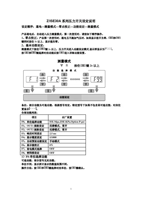
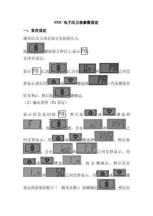
SMC表头的设定1.单位的确定a)按中间键“set”2S以上进入“F0~F99”界面。
b)用▲和▼两键选择F0,按中“set”进入单位选择界面。
如下图:进入单位界面c)用▲和▼选择自已想要的单位,表头显示与单位的图画如下:单位界面注:表头不同型号所包含的单位个数也不同。
d)选择好单位,按“set”2S以上即设定好单位,返回了显示界面。
2.a/b接点(常开/常闭)的设定a)按中间键“set”2S以上进入“F0~F99”界面。
b)用▲和▼两键选择F1,按中“set”进入输出类别选择界面。
如下图类别选择界面c)用▲和▼两键选择HY5 ,按“set”确定进入输出模式选择。
输出模式d)用▲和▼两键选择,按“set”确定把表头设为常开或常闭型。
接点选择3.最小值与最大值设定(以常开为例)a)用▲和▼两键选择1-P,按“set”确定进入了最小值设定,如下图:最小值b)加或减小一位,按“set”确定。
c) 最小值设定确定后,就会进入最大值设定。
如下图:最大值d) 用▲和▼两键可以设定最小值,每按▲和▼一次设定值会增加或减小一按“set”确定。
3.标准值的设定当最大值设定后,长按“set”2S以上返回到表头的显示界面。
Ⅰ、正压表头时:———打开调压阀开关把气压值调至到标准值。
Ⅱ、负压表头时:a)把负压的吸嘴外放上产品。
b)打开真空产生器。
c)打开调压阀开关把气压值调至到标SMC表头的设定检验用调压阀上的调节开关来调节气压的大小,来检验表头的最大与最小值是否正确。
a)当调节的气压大于最大值或小于最小值时,出现警报,则说明设定正确。
---把气压调回正常值。
表头就可以工作使用。
b)当调节的气压大于最大值或小于最小值时,不出现警报,则说明设定错误。
---表头需要检查重新设定。
注:如是负压表头:要把负压的吸嘴外放上产品并打开真空产生器。
才能按上面步骤检验。
http://www.diancifa.cc
1
产品名称:SMC数字压力开关接线
压力开关采用高精度、高稳定性能的压力传感器和变送电路,再经专用CPU模块化信号处理技术,
实现对介质压力信号的检测、显示、报警和控制信号输出。压力开关可以广泛用于石油、化工、冶
金、电力、供水等领域中对各种气体、液体的表压、绝压的测量控制,是工业现场理想的智能化测
控仪表。压力开关广泛用于航空航天和军工领域,如M1A1坦克、阿波罗飞船、波音747、空客
A320、F22、F117等产品制造。
http://www.diancifa.cc
2
http://www.diancifa.cc
3