SMC压力传感器调整说明书 ZSE AISE A
- 格式:pdf
- 大小:603.08 KB
- 文档页数:12
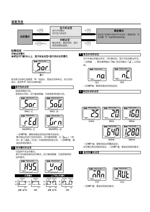
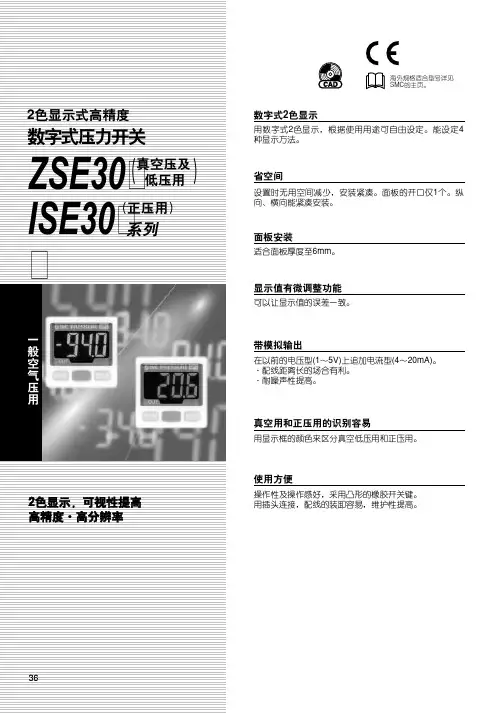
文件No.PS※※-OMS0006CN-G数字式压力开关ZSE20(F)ISE20安全注意事项2型式表示・型号体系8产品各部位名称及功能10用语说明11安装·设置14设置方法14配管方法16配线方法18设定概要[测量模式] 20 压力设定21 3步设定模式22 简易设定模式24功能选择模式26功能选择模式说明26出厂设定26 F0 单位切换功能28 F1 OUT1的设定29 F3 数字滤波器的设定32 F4 自动预设功能的设定33 F6 显示值微调的设定35 F10 子画面的设定36 F11 显示分辨率的设定41 F80 省电模式的设定42 F81 密码输入的设定43 F82 线名输入的设定45 F90 全功能的设定46 F98 输出确认48 F99 恢复出厂设置49其他设定50维护54忘记密码的场合54故障一览表55规格62规格表62外形尺寸图64安全注意事项此处所示的注意事项是为了确保您能安全正确地使用本产品,预先防止对您和他人造成危害和伤害而制定的。
这些注意事项,按照危害和损伤的大小及紧急程度分为「注意」「警告」「危险」三个等级。
无论哪个等级都是与安全相关的重要内容,所以除了遵守国际规格(ISO/IEC)、日本工业规格(JIS)*1)以及其他安全法规*2)外,这些内容也请务必遵守。*1) ISO 4414: Pneumatic fluid power -- General rules relating to systemsISO 4413: Hydraulic fluid power -- General rules relating to systemsIEC 60204-1: Safety of machinery -- Electrical equipment of machines (Part 1: General requirements)ISO 10218: Manipulating industrial robots-SafetyJIS B 8370: 空气压系统通则JIS B 8361: 油压系统通则JIS B 9960-1: 机械类的安全性-机械的电气装置(第1部:一般要求事项)JIS B 8433: 产业用操作机器人-安全性等*2) 劳动安全卫生法等注意误操作时,有人员受伤的风险以及物品破损的风险。警告误操作时,有人员受到重大伤害甚至死亡的风险。
Z/ISE30A 系列压力开关设定说明设定顺序:通电—测量模式—零点校正—功能设定—测量模式产品通电后,自动进入压力测量模式,第一次使用时,请按如下顺序操作。
1、零点校正:产品第一次使用时,通电且不施加气压时,如果显示值不为零,和键同时按住1s 以上,显示值归零。
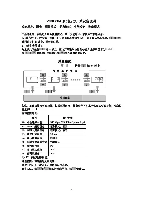
2、基本功能设定:测量模式下按住键2s 以上,压力开关进入功能设定模式,显示屏显示为。
按和键选择对应功能后按进入详细功能设置。
备注:部分功能为可选功能,根据型号而定。
特定型号下如果不包含某可选功能,对应位置显示。
全部功能列表:项目出厂设置F0:单位选择功能 ISE-Mpa,ZSE-KPa,Option P-psi F1:OUT1规格设定 迟滞模式,常开F2:OUT2规格设定 迟滞模式,常开 F3:响应时间设定 2.5 ms F4:显示精度设定 1/1000 F5:自动预设功能设定 手动模式F6:显示值校正 0% F7:省电模式选择 OFF F8:密码锁设定OFF1)F0-单位选择功能可选功能,部分型号无此功能。
单位不同,显示屏开显示的数值范围不同。
操作方法:按和键选择对应单位,按键确认。
测量模式按住键2s 以上功 能 选 择 模 式功能设定2)F1-OUT1输出规格设定方法:此部分可设置输出类别(迟滞型/比较型)和输出模式(常开/常闭)设定。
按键进入单位选择模式按和键选择对应单位交替显示按键完成设定返回到功能选择模式,屏幕显示F0F0-单位选择功能设定完成输出模式常开型 出厂时默认设置常闭型迟滞模式(出厂时默认设置) 压力输出迟滞(H-1)压力输出压力输出迟滞(H-1)压力输出比较模式(也称窗口比较模式) 迟滞模式(出厂时默认设置) 比较模式(也称窗口比较模式) 迟滞(H1) 迟滞(H1)迟滞(H1) 迟滞(H1)功能选择模式下按和至屏幕显示,然后按进入OUT1规格设定。
压力设定状态:此状态下设定压力开关输出的ON/OFF 点。
以迟滞型为例:输出方法:当压力超过设定值时,开关输出变为ON 。

Z/ISE30A 系列压力开关设定说明设定顺序:通电—测量模式—零点校正—功能设定—测量模式产品通电后,自动进入压力测量模式,第一次使用时,请按如下顺序操作。
1、零点校正:产品第一次使用时,通电且不施加气压时,如果显示值不为零,和键同时按住1s 以上,显示值归零。
2、基本功能设定:测量模式下按住键2s 以上,压力开关进入功能设定模式,显示屏显示为。
按和键选择对应功能后按进入详细功能设置。
备注:部分功能为可选功能,根据型号而定。
特定型号下如果不包含某可选功能,对应位置显示。
全部功能列表:项目出厂设置F0:单位选择功能 ISE-Mpa,ZSE-KPa,Option P-psi F1:OUT1规格设定 迟滞模式,常开F2:OUT2规格设定 迟滞模式,常开 F3:响应时间设定 2.5 ms F4:显示精度设定 1/1000 F5:自动预设功能设定 手动模式F6:显示值校正 0% F7:省电模式选择 OFF F8:密码锁设定OFF1)F0-单位选择功能可选功能,部分型号无此功能。
单位不同,显示屏开显示的数值范围不同。
操作方法:按和键选择对应单位,按键确认。
测量模式按住键2s 以上功 能 选 择 模 式功能设定2)F1-OUT1输出规格设定方法:此部分可设置输出类别(迟滞型/比较型)和输出模式(常开/常闭)设定。
按键进入单位选择模式按和键选择对应单位交替显示按键完成设定返回到功能选择模式,屏幕显示F0F0-单位选择功能设定完成输出模式常开型 出厂时默认设置常闭型迟滞模式(出厂时默认设置) 压力输出迟滞(H-1)压力输出压力输出迟滞(H-1)压力输出比较模式(也称窗口比较模式) 迟滞模式(出厂时默认设置) 比较模式(也称窗口比较模式) 迟滞(H1) 迟滞(H1)迟滞(H1) 迟滞(H1)功能选择模式下按和至屏幕显示,然后按进入OUT1规格设定。
压力设定状态:此状态下设定压力开关输出的ON/OFF 点。
以迟滞型为例:输出方法:当压力超过设定值时,开关输出变为ON 。
文件No.PS※※-OMM0006-A 使用说明书产 品 名 称数字式压力开关型式/系列/型号ZSE40A(F)ISE40A目录安全注意事项 2 型式表示・型号体系 9 产品各部品名称及功能 11 用语的定义及用语集 12 安装・设置 15 设置方法 15 配管方法 17 配线方法 19 压力设定 21 什么是设定模式 21 功能设定 23 什么是功能选择模式 23 出厂设定 23 F0 单位切换功能 25 F1 OUT1的设定 26 F2 OUT2的设定 29 F3 响应时间的设定 31 F4 自动预设功能的设定 32 F5 模拟输出/自动移位输入的设定 34 F6 显示值微调整的设定 36 F11 分辨率的设定 37 F80 省电模式的设定 38 F81密码输入的设定 39 特殊功能的设定 40 F90 全功能的设定 40 F97 复制功能的选择 42 F98 输出确认 44 F99 恢复出厂设置 46 其他设定 47 维护 50 忘记密码的情况 51 故障的消除 52 规格 59 规格表 59 外形尺寸图 61安全注意事项这里所示的注意事项是为了能安全正确的使用本产品,预先防止对您和他人造成危害或损失。
为了表示这些事项的危险程度,将注意事项分成「注意」「警告」和「危险」三个等级。
请您也遵守和安全相关的其他重要内容,如国际规格(ISO/IEC)、日本工业规格(JIS)※1以及其他安全法规※2。
*1) ISO 4414: Pneumatic fluid power -- General rules relating to systemsISO 4413: Hydraulic fluid power -- General rules relating to systemsIEC 60204-1: Safety of machinery -- Electrical equipment of machines (Part 1: General requirements) ISO 10218-1: Robots for industrial environments—Safety requirements –Part 1: RobotJIS B 8370: 空气压系统通则JIS B 8361: 油压系统通则JIS B 9960-1: 机械类的安全性-机械的电气装置(第1部:一般要求事项)JIS B 8433-1: 工业机器人- 安全要求事项-第1部: 机器人等*2) 劳动安全卫生法 等注意: 错误操作时,人和设备可能受到损伤的事项。
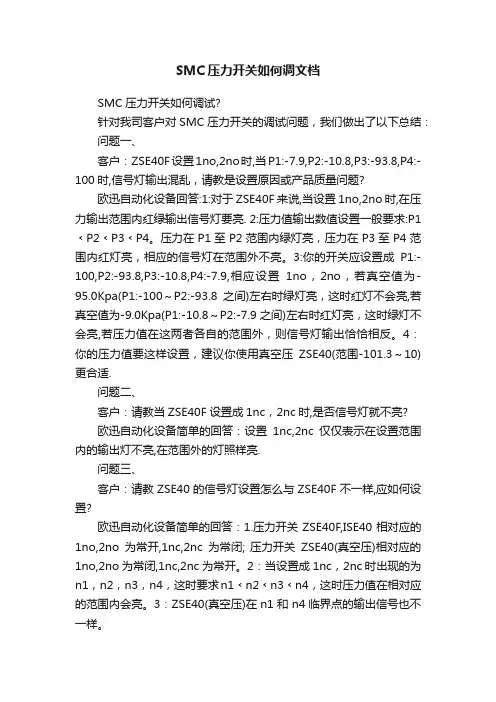
SMC压力开关如何调文档SMC压力开关如何调试?针对我司客户对SMC压力开关的调试问题,我们做出了以下总结:问题一、客户:ZSE40F设置1no,2no时,当P1:-7.9,P2:-10.8,P3:-93.8,P4:-100时,信号灯输出混乱,请教是设置原因或产品质量问题?欧迅自动化设备回答:1:对于ZSE40F来说,当设置1no,2no时,在压力输出范围内红绿输出信号灯要亮. 2:压力值输出数值设置一般要求:P1﹤P2﹤P3﹤P4。
压力在P1至P2范围内绿灯亮,压力在P3至P4范围内红灯亮,相应的信号灯在范围外不亮。
3:你的开关应设置成P1:-100,P2:-93.8,P3:-10.8,P4:-7.9,相应设置1no,2no,若真空值为-95.0Kpa(P1:-100~P2:-93.8之间)左右时绿灯亮,这时红灯不会亮,若真空值为-9.0Kpa(P1:-10.8~P2:-7.9之间)左右时红灯亮,这时绿灯不会亮,若压力值在这两者各自的范围外,则信号灯输出恰恰相反。
4:你的压力值要这样设置,建议你使用真空压ZSE40(范围-101.3~10)更合适.问题二、客户:请教当ZSE40F设置成1nc,2nc时,是否信号灯就不亮?欧迅自动化设备简单的回答:设置1nc,2nc仅仅表示在设置范围内的输出灯不亮,在范围外的灯照样亮.问题三、客户:请教ZSE40的信号灯设置怎么与ZSE40F不一样,应如何设置?欧迅自动化设备简单的回答:1.压力开关ZSE40F,ISE40相对应的1no,2no为常开,1nc,2nc为常闭; 压力开关ZSE40(真空压)相对应的1no,2no为常闭,1nc,2nc为常开。
2:当设置成1nc,2nc时出现的为n1,n2,n3,n4,这时要求n1﹤n2﹤n3﹤n4,这时压力值在相对应的范围内会亮。
3:ZSE40(真空压)在n1和n4临界点的输出信号也不一样。
附一:SMC压力开关的使用一:使用环境1:适合流体:空气、非腐蚀性气体;2:使用温度:保存时0~50℃,工作时10~50℃。
SMC压力传感器调整说明书SMC压力传感器是一种广泛应用于工业生产中的重要设备。
作为一种关键的检测器,它能够帮助操作者监测工业生产中的压力值,并进行调整,从而确保产品的质量和生产的稳定性。
在实际的应用过程中,对SMC压力传感器的正确调整是至关重要的。
本文将为大家提供一份详细的SMC压力传感器调整说明书。
仪器器材准备在进行SMC压力传感器的调整之前,我们首先需要准备好一些仪器和器材。
这些器材的使用是为了保证我们能够进行准确、稳定和可靠的测量。
主要的器材如下:1. SMC压力传感器2. 0-5V电压信号发生器3. 电子式万用表4. 气源压力表5. 压力校验器6. 电脑或手机APP调整步骤1. 调整输出信号电压首先,我们需要通过电压信号发生器来给SMC压力传感器提供一个规定的电压输入信号。
在此之前,我们需要先将电压信号发生器的信号输出与SMC压力传感器的输入端口相连接。
调整过程中,我们需要慢慢提高输入信号,直到SMC压力传感器输出的电压信号为满电压的80%为止。
在此之后,我们需要将电压信号逐步降低,直到输出信号电压达到满量程的10-90%。
2. 调整零点偏移在电压信号的调整完成之后,下一步我们需要对SMC压力传感器的零点偏移进行校准。
在此之前,我们需要将电压信号发生器的输出电压设置为0,这样可以避免误差。
调整过程中,我们需要根据电子式万用表测量出SMC压力传感器当前的输出电压,并与实际的零点输出电压进行比较。
如果出现偏差,我们需要调整压力传感器的零点来进行校准。
3. 调整满量程在进行零点偏移校准之后,我们需要对SMC压力传感器的满量程进行校准。
在此之前,我们需要按照之前的方法调整电压信号到满量程。
调整过程中,我们需要根据电子式万用表测量出SMC压力传感器当前的输出电压,并与实际的满量程输出电压进行比较。
如果出现偏差,我们需要调整压力传感器的满量程来进行校准。
4. 调整灵敏度和输出信号最后一步,我们需要根据实际情况来调整SMC压力传感器的灵敏度和输出信号。
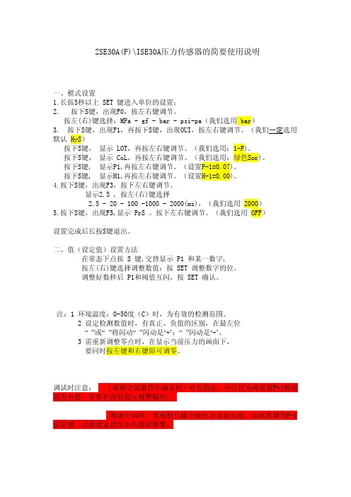
ZSE30A(F)\ISE30A压力传感器的简要使用说明一、模式设置1.长按5秒以上SET键进入单位的设置;2.按下S键,出现F0,按左右键调节。
按左(右)键选择:MPa-gf-bar-psi-pa(我们选用bar)3.按下S键,出现F1,再按下S键,出现OUI,按左右键调节。
(我们一定选用默认HyS)按下S键,显示LOT,再按左右键调节。
(我们选用:1-P)。
按下S键,显示CoL,再按左右键调节。
(我们选用:绿色Sor)。
按下S键,显示P1,再按左右键调节。
(设置P-1=0.07)。
按下S键,显示H1,再按左右键调节。
(设置H-1=0.00)。
4.按下S键,出现F3,按下左右键调节。
显示2.5,按左(右)键选择2.5-20-100-1000-2000(ms),(我们选用2000)5.按下S键,出现F5,显示PrS。
按下左右键调节。
(我们选用OFF)设置完成后长按S键退出。
二、值(设定值)设置方法在常态下点按S键,交替显示P1和某一数字,按左(右)键选择调整数值;按SET调整数字的位。
调整好数秒后P1和阀值互闪,按SET确认。
注:1环境温度:0-50度(C)时,为有效的检测范围。
2设定检测数值时,有真正、负值的区别,在最左位“”或“”将闪动“”闪动是‘+’;“”闪动是‘-’。
3需重新调整零点时,在显示当前压力的画面下,要同时按左键和右键即可调零。
调试时注意:(现场空试条件不满足时)对点的话,可以认为将设置P-1的值设为负值,看看有没有超压报警输出)。
现场空试时,要观察日储斗处压力表显示值。
由此来调节P-1设定值。
以防设定值过小出现误报警。
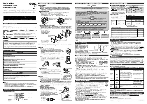
Other SettingsSummary of Product partsSimple Setting ModeTroubleshootingNote: Specifications are subject to change without prior notice and any obligation on the part of the manufacturer.© 2017 SMC Corporation All Rights ReservedAkihabara UDX 15F, 4-14-1, Sotokanda, Chiyoda-ku, Tokyo 101-0021, JAPANPhone: +81 3-5207-8249 Fax: +81 3-5298-5362URL Specifications/Outline with Dimensions (in mm)Refer to the product catalog or SMC website (URL ) for moreinformation about the product specifications and outline dimensions.PS※※-OMU0004 InstallationMountingMount the optional bracket and panel mount adapter to the pressure switch.When the pressure switch is to be mounted in a place where water and dustsplashes occur, insert a tube into the air-relieving port of the pressure switch.(Refer to "Tube attachment")Mounting with bracketMount the bracket to the body with mounting screws (Self tapping screws:Nominal size 3 x 8L (2 pcs)), then set the body to the specified position.∗: Tighten the bracket mounting screws to a torque of 0.5±0.05 Nm.Self tapping screws are used, and should not be re-used several times.∗: The panel mount adaptercan be rotated through 90degrees for mounting.•Bracket A (Part No.: ZS-46-A1)•Bracket B (Part No.: ZS-46-A2)Mounting with panel mount adapterMount part (a) to the front of the body and fix it. Then insert the body with (a) intothe panel until (a) comes into contact with the panel front surface. Next, mountpanel for fixing.•Panel mount adapter(Part No.: ZS-46-B)Panel mount adapter +Front protective cover(Part No.: ZS-46-D)WiringWiring connectionsUse a separate route for the product wiring and any power or high voltage wiring.Otherwise, malfunction may result due to noise.If a commercially available switching power supply is used, be sure to ground theframe ground (FG) terminal. If the switching power supply is connected for use,switching noise will be superimposed and it will not be able to meet the productspecifications. In that case, insert a noise filter such as a line noise filter/ferritebetween the switching power supplies or change the switching power supply tothe series power supply.How to use connectorConnector attachment/detachmentWhen connecting the connector, insert itstraight onto the pins, holding the lever andconnector body, and lock the connector bypushing the lever hook into the concavegroove on the housing.To detach the connector, remove the hookfrom the groove by pressing the leverdownward, and pull the connector straight out.DC(+)OUT1OUT2FUNCDC(-)BrownBlackWhiteGrayBluePipingTightening the connection threadFor connecting to the body (piping specification: -M5)After hand tightening, apply a spanner of the correct size tothe spanner flats of the piping body, and tighten with a 1/6 to1/4 rotation.As a reference, the tightening torque is 1 to 1.5 Nm.(When replacing the piping adapter ZS-46-N∗, tighten it usingthe same method.)Piping specification: -01, -N01After hand tightening, hold the hexagonal spanner flats of thepressure port with a spanner, and tighten with 2 to 3 rotations.As a reference, the tightening torque is 3 to 5 Nm.When tightening, do not hold the pressure switch body with aDefault settingsWhen the pressure exceeds the setvalue, the switch will be turned on.When the pressure falls below theset value by the amount ofhysteresis or more, the switch willbe turned off. The default setting isto turn on the pressure switch whenthe pressure reaches the centre ofthe atmospheric pressure and upper limit of the rated pressure range. If this condition,shown to the right, is acceptable, then keep these settings.Error indication functionThis function is to display error location and content when a problem or error has occurred.above are displayed, please contact SMC.Refer to the SMC website (URL ) for more information abouttroubleshooting.Power is supplied.button between1 and 3 sec.∗:The outputs will continue to operate during setting.∗:If a button operation is not performed for 3 seconds during the setting, the display will flash.(This is to prevent the setting from remaining incomplete if, for instance, an operator were to leave duringsetting.)∗:3 step setting mode, simple setting mode and function selection mode settings are reflected each other.[3 step setting mode (hysteresis mode)]orcan be changed in the same way.button once when the item to beThe set value on the sub display (right) will startflashing.orbutton.buttons are pressed and held simultaneously for 1 second orlonger, the set value is displayed as [- - -], and the set value will be the same as thecurrent pressure value automatically (snap shot function).Afterwards, it is possible to adjust the value by pressing button.button to complete the setting.The pressure switch turns on within a set pressure range (from P1L to P1H) duringwindow comparator mode.Set P1L, the lower limit of the switch operation, and P1H, the upper limit of the switchoperation and WH1 (hysteresis) following the instructions given above.(When reversed output is selected, the sub display (left) shows [n1L] and [n1H].)∗:Set OUT2 in the same way. (ex. P_2, H_2)∗:Setting of the normal/reverse output switching and hysteresis/window comparator mode switchingare performed with the function selection mode [F 1] OUT1 setting and [F 2] OUT2 setting.value[F 0] Units selection functionPeak/bottom value indicationbutton inmeasurement mode.Snap shot functionbuttons for 1 secondor longer simultaneously. Then, the set value of the sub display (right) shows [- - -], andthe values corresponding to the current pressure values are automatically displayed.Zero-clear functionbuttons are pressed for 1 second orlonger simultaneously, the main display shows [- - -], and the reset to zero.The display returns to measurement mode automatically.Key-lock functionTo set each of these functions, refer to the SMC website(URL ) for more detailed information, or contact SMC.button between 1 and 3 seconds in measurementmode. [SEt] is displayed on the main display. When the button is releasedwhile in the [SEt] display, the current pressure value is displayed on themain display, [P_1] or [n_1] is displayed on the sub display (left), and theset value is displayed on the sub display (right) (Flashing).or button to(The snap shot function can be used.)or button to set the(The snap shot function can be used.)or button, the delay time of the switch output can be selected.button for 2 seconds or longer to complete the setting.∗:If the button is pressed for less than 2 seconds, the setting will moves to the OUT2 setting.In the window comparator mode, set P1L, the lower limit of the switch operation, andP1H, the upper limit of the switch operation, WH1 (hysteresis) and dt1 (delay time)following the instructions given above.(When reversed output is selected, the sub display (left) shows [n1L] and [n1H].)∗:Set OUT2 in the same way.Function selection modebuttonbetween 3 and 5 seconds, to display [F 0].Select to display the function to be changed[F button for 2seconds or longer in function selection modeto return to measurement mode.∗:Some products do not have all the functions. If no functionis available or selected due to configuration of otherfunctions, [- - -] is displayed on the sub display (right).Names of individual partsRefer to the product catalog or SMC website (URL ) for moreinformation about panel cut-out and mounting hole dimensions.Pressure Setting3 Step Setting Mode(URL ) for more detailed information, or contact SMC.MaintenanceHow to reset the product after a power cut or forcible de-energizingThe setting of the product will be retained as it was before a power cut or de-energizing.The output condition is also basically recovered to that before a power cut or de-energizing, but may change depending on the operating environment. Therefore, checkthe safety of the whole installation before operating the product. If the installation is usingaccurate control, wait until the product has warmed up (approximately 10 to 15 minutes). Safety InstructionsBefore UseDigital Pressure SwitchZSE20B(F)/ISE20BThank you for purchasing an SMC ZSE20B(F)/ISE20B Series Digital Pressure Switch.Please read this manual carefully before operating the product and make sure youunderstand its capabilities and limitations. Please keep this manual handy for futurereference.Safety InstructionsThese safety instructions are intended to prevent hazardous situations and/orequipment damage.These instructions indicate the level of potential hazard with the labels of "Caution","Warning" or "Danger". They are all important notes for safety and must be followed inaddition to International standards (ISO/IEC) and other safety regulations.OperatorSwitch ONAt normal output Switch OFFSet valueP_1HysteresisH_1TimePressureDefault settingThe default setting is as follows.If no problem is caused by this setting,keep these settings.Connector pin numbers[F 2] Setting of OUT2Same setting as [F 1] OUT1.NOTE•The direct current power supply to be used should be UL approved as follows:Circuit (of Class 2) which is of maximum 30 Vrms (42.4 V peak), with UL1310 Class2 power supply unit or UL1585 Class 2 transformer.•The product is a UL approved product only if it has a mark on the body.Tube attachmentWhen this pressure switch is used in a place wherewater and dust splashes may occur, insert a tube in theair-relieving port, and bring piping of the opposite sideup to the safe position to keep it from water and dust.(See the right figure.)∗: The tube should be inserted to the end of the air-relieving port.∗: SMC TU0425 (polyurethane, O.D ø4, I.D ø2.5) is a suitable tubing.。
SMC压力传感器调整说明书ZSE30AISE30A关键信息项:1、传感器型号:ZSE30A/ISE30A2、调整目的3、调整工具4、调整步骤5、安全注意事项6、故障排除方法1、引言本协议旨在为用户提供关于 SMC 压力传感器 ZSE30A/ISE30A 的详细调整说明,以确保其正常运行和准确测量压力。
11 适用范围本协议适用于 SMC 压力传感器 ZSE30A/ISE30A 的调整操作。
2、调整目的21 确保传感器测量精度通过调整,使传感器能够准确测量压力值,减少误差。
22 适应不同的工作环境和压力范围根据实际工作需求,调整传感器的参数,以适应各种工作条件。
23 优化传感器性能提高传感器的响应速度、稳定性和可靠性。
3、调整工具31 专用调试设备如 SMC 提供的特定调试工具或软件。
32 标准压力校验仪用于提供准确的压力标准值,以校准传感器。
33 螺丝刀等常用工具用于拆卸和安装传感器的外壳及相关部件。
4、调整步骤41 准备工作411 关闭相关设备的电源,确保操作安全。
412 将传感器从系统中拆卸下来,放置在干净、平稳的工作台上。
42 外观检查421 检查传感器外壳是否有损坏、变形等情况。
422 检查传感器的连接接口是否清洁、无异物。
43 连接调试设备431 将专用调试设备或软件与传感器正确连接。
432 按照调试设备的说明书进行设置和初始化。
44 压力校准441 使用标准压力校验仪向传感器施加不同的压力值。
442 观察传感器的输出值,并与标准压力值进行对比。
443 通过调试设备调整传感器的参数,使输出值与标准压力值相符。
45 功能测试451 对调整后的传感器进行功能测试,包括压力上升和下降时的响应情况。
452 检查传感器在不同压力范围内的稳定性和重复性。
46 安装与恢复461 将调整好的传感器安装回原系统。
462 开启相关设备的电源,检查传感器的工作状态是否正常。
5、安全注意事项51 在操作过程中,务必遵循相关的安全操作规程,防止发生意外事故。
SMC压力开关如何调试?发表于:2019年07月30日17:02转发0针对我司客户对SMC压力开关的调试问题,我们做出了以下总结:问题一、客户:ZSE40F设置1no,2no时,当P1:-7.9,P2:-10.8,P3:-93.8,P4:-100时,信号灯输出混乱,请教是设置原因或产品质量问题?欧迅自动化设备回答:1:对于ZSE40F来说,当设置1no,2no时,在压力输出范围内红绿输出信号灯要亮. 2:压力值输出数值设置一般要求:P1﹤P2﹤P3﹤P4。
压力在P1至P2范围内绿灯亮,压力在P3至P4范围内红灯亮,相应的信号灯在范围外不亮。
3:你的开关应设置成P1:-100,P2:-93.8,P3:-10.8,P4:-7.9,相应设置1no,2no,若真空值为-95.0Kpa(P1:-100~P2:-93.8之间)左右时绿灯亮,这时红灯不会亮,若真空值为-9.0Kpa(P1:-10.8~P2:-7.9之间)左右时红灯亮,这时绿灯不会亮,若压力值在这两者各自的范围外,则信号灯输出恰恰相反。
4:你的压力值要这样设置,建议你使用真空压ZSE40(范围-101.3~10)更合适.问题二、客户:请教当ZSE40F设置成1nc,2nc时,是否信号灯就不亮?欧迅自动化设备简单的回答:设置1nc,2nc仅仅表示在设置范围内的输出灯不亮,在范围外的灯照样亮.问题三、客户:请教ZSE40的信号灯设置怎么与ZSE40F不一样,应如何设置?欧迅自动化设备简单的回答:1.压力开关ZSE40F,ISE40相对应的1no,2no为常开,1nc,2nc为常闭;压力开关ZSE40(真空压)相对应的1no,2no为常闭,1nc,2nc为常开。
2:当设置成1nc,2nc时出现的为n1,n2,n3,n4,这时要求n1﹤n2﹤n3﹤n4,这时压力值在相对应的范围内会亮。
3:ZSE40(真空压)在n1和n4临界点的输出信号也不一样。
附一:SMC压力开关的使用一:使用环境1:适合流体:空气、非腐蚀性气体;2:使用温度:保存时0~50℃,工作时10~50℃。
Insertion of batteriesSlide the cover of the case open to insert the batteries.Use 2 x AA (LR6) alkaline dry cell batteries.When inserting the batteries, pay attention to the polarities and insert them inthe correct direction.After insertion, ensure the cover is closed correctly.AssemblyPeak hold: "P"Power button(2 pcs.)Mounting of the high voltage measuring handle (option)1. Insert the sensor into the handle in thedirection shown.2. Fix the cable to the handle as shown.3. The assembly is complete and the handle isnow ready for use.Procedure1. Insert the batteries.2. Connect the ground wire.Connect the ground wire to a point suitable for connection to an externalprotective earthing system.The position for attaching the ground wire to the Handheld meter is shownbelow.button.4. Move the sensor closer to the position 50 mm away from the measured target.Gradually bring the sensor closer to the measured target from a distance, andstop measurement immediately if the displayed value indicates overflow(HHH) or underflow (LLL).(The target has a high charged potential that is highly dangerous. Themeasured value does not change even if the distance is shortened.)5. Check the display.t∗Names of individual parts•DisplayFunction settingsis pressed with the powerturned on.All indications are displayed for 1 s.after the power supply is turned on.•Sensoris pressed for 3 s. or more with theoff the power supply.(For details, refer to Auto power-OFF function.)Turn off the power supply after using the product to keep the life of batteriesas long as possible.Auto power-OFFIf no button is pressed for 5 min. or more with thepower supply on, the power supply will turn offautomatically.is pressed for 6 s. or more with the power supply off, the(When this auto power-off extension is activated, indications on the displaywill keep flashing for 3 s.)is pressed with thewill be changed to instantaneousvalue, peak hold value, bottomhold value and instantaneousvalue, in that order.∗•Peak hold valueThe maximum charged potential and "P" are displayed.The maximum charged potential is continuously detected and updated fromwhen the peak hold is started. If the value over the held maximum chargedpotential is detected, the display will change.•Bottom hold valueThe minimum charged potential and "b" are displayed.The minimum charged potential is continuously detected and updated fromwhen the bottom hold is started. If the value under the held minimumcharged potential is detected, the display will change.Zero clearA displayed value can be adjusted to zero atmeasured charged potential in a range of ±5%F.S. ofdefault potential.(There will be a slight displacement, depending onthe deviation of the sensor itself and ambientare pressed for 6 s. or more with the power supply on,recovered automatically.Once the power supply is turned off, the offset value for zero clear is cleared.is pressed while the charged potentialbutton again to turn off the back light.Battery lowWhen the battery voltage becomes low "L" will bedisplayed. The display will vary depending on howmuch battery is left.The display resolution changes depending on the measured charged potentialvalue.value indicationHandheld ElectrostaticMeterOperation ManualIZH10Thank you for purchasing an SMC IZH10 Series Handheld Electrostatic Meter.Please read this manual carefully before operating the product and make sure youunderstand its capabilities and limitations.Please keep this manual handy for future reference.To obtain more detailed information about operating this product, pleaserefer to the SMC website (URL ) or contact SMCdirectly.These safety instructions are intended to prevent hazardous situations and/orequipment damage.These instructions indicate the level of potential hazard with the labels of"Caution", "Warning" or "Danger". They are all important notes for safety and mustbe followed in addition to International standards (ISO/IEC) and other safetyregulations.OperatorSafety Instructions TroubleshootingError IndicationThis function is to display error location and content when a problem or an error occurs.contact SMC.±1 to ±20 kVMinimum display unit:0.1 kV0 to±0.99 kVMinimum display unit:0.01 kV<Display example>Akihabara UDX 15F, 4-14-1, Sotokanda, Chiyoda-ku, Tokyo 101-0021, JAP ANPhone: +81 3-5207-8249 Fax: +81 3-5298-5362URL Note: Specifications are subject to change without prior notice and any obligation on the part of the manufacturer.© 2011 SMC Corporation All Rights ReservedSpecificationsOutline with Dimensions (in mm)Refer to the product catalogue or SMC website (URL ) formore information about the product specifications and outline dimensions.Refer to the SMC website (URL ) for more informationabout troubleshooting.。
Z/ISE30A 系列压力开关设定说明设定顺序:通电—测量模式—零点校正—功能设定—测量模式产品通电后,自动进入压力测量模式,第一次使用时,请按如下顺序操作。
1、零点校正:产品第一次使用时,通电且不施加气压时,如果显示值不为零,和键同时按住1s 以上,显示值归零。
2、基本功能设定:测量模式下按住键2s 以上,压力开关进入功能设定模式,显示屏显示为。
按和键选择对应功能后按进入详细功能设置。
备注:部分功能为可选功能,根据型号而定。
特定型号下如果不包含某可选功能,对应位置显示。
全部功能列表:项目出厂设置F0:单位选择功能 ISE-Mpa,ZSE-KPa,Option P-psi F1:OUT1规格设定 迟滞模式,常开F2:OUT2规格设定 迟滞模式,常开 F3:响应时间设定 2.5 ms F4:显示精度设定 1/1000 F5:自动预设功能设定 手动模式F6:显示值校正 0% F7:省电模式选择 OFF F8:密码锁设定OFF1)F0-单位选择功能可选功能,部分型号无此功能。
单位不同,显示屏开显示的数值范围不同。
操作方法:按和键选择对应单位,按键确认。
测量模式按住键2s 以上功 能 选 择 模 式功能设定2)F1-OUT1输出规格设定方法:此部分可设置输出类别(迟滞型/比较型)和输出模式(常开/常闭)设定。
按键进入单位选择模式按和键选择对应单位交替显示按键完成设定返回到功能选择模式,屏幕显示F0F0-单位选择功能设定完成输出模式常开型 出厂时默认设置常闭型迟滞模式(出厂时默认设置) 压力输出迟滞(H-1)压力输出压力输出迟滞(H-1)压力输出比较模式(也称窗口比较模式) 迟滞模式(出厂时默认设置) 比较模式(也称窗口比较模式) 迟滞(H1) 迟滞(H1)迟滞(H1) 迟滞(H1)功能选择模式下按和至屏幕显示,然后按进入OUT1规格设定。
压力设定状态:此状态下设定压力开关输出的ON/OFF 点。
以迟滞型为例:输出方法:当压力超过设定值时,开关输出变为ON 。
Instruction ManualHigh Precision Digital Pressure SwitchThe intended use of this digital pressure switch is to measure, monitorand display pressure and to provide an output signal.These safety instructions are intended to prevent hazardous situationsand/or equipment damage. These instructions indicate the level ofpotential hazard with the labels of “Caution,” “Warning” or “Danger.”They are all important notes for safety and must be followed in additionto International Standards (ISO/IEC) *1), and other safety regulations.*1) ISO 4414: Pneumatic fluid power - General rules relating to systems.ISO 4413: Hydraulic fluid power - General rules relating to systems.IEC 60204-1: Safety of machinery - Electrical equipment of machines.(Part 1: General requirements)ISO 10218-1: Robots and robotic devices - Safety requirements forindustrial robots - Part 1: Robots.•Refer to product catalogue, Operation Manual and HandlingPrecautions for SMC Products for additional information.• Keep this manual in a safe place for future reference.Caution Caution indicates a hazard with a low level of risk which, ifnot avoided, could result in minor or moderate injury.Warning Warning indicates a hazard with a medium level of riskwhich, if not avoided, could result in death or serious injury.Danger Danger indicates a hazard with a high level of risk which, ifnot avoided, will result in death or serious injury.Warning•Always ensure compliance with relevant safety laws andstandards.•All work must be carried out in a safe manner by a qualified person incompliance with applicable national regulations.•This product is class A equipment intended for use in an industrialenvironment. There may be potential difficulties in ensuringelectromagnetic compatibility in other environments due to conductedor radiated disturbances.Otherwise electric shock, malfunction or product damage can result.•Refer to the operation manual on the SMC website (URL:https://) for more safety instructions.2 Specifications2.1 General specifications∗1: Value without digital filter (at 0 ms).∗2: If the applied pressure fluctuates around the set value, the hysteresis must beset to a value more than the amount of fluctuation or chattering will occur.∗3: This setting is only available for models with the units selection function. OnlyMPa or kPa is available for models without this function.∗4: The response time indicates when the set value is 90% in relation to the stepinput.2.2 Piping / Weight specificationsProduct No. M5 01 N01 C4H C6H N7H C4L C6L N7LPort size M5 x0.8 R1/8NPT1/8φ4 mmφ5/32inchφ6mmφ1/4inchφ4 mmφ5/32inchφ6mmφ1/4inchMaterialsinfluidcontactPressure-sensing part SiliconPiping port(Common) PBT, CB156, heat resistant PPS, O-ring: HNBRPiping port -C3604(electrolessnickelplating),SUS304,NBRPOM, SUS304, NBR, C3604Weight Body [g] 22 32 34 25 26 27 28 28 34Lead wire +connector +35 g2.3 Cable specificationsConductor area 0.15 mm2 (AWG26)Insulator outside diameter 1.0 mmColour Brown, Blue, Black (3 core)Sheath outside diameter φ3.4WarningSpecial products (-X) might have specifications different from thoseshown in this section. Contact SMC for specific drawings.3 Name and function of product partsOperation light: Displays the switch operating condition.LCD display: Displays the current status of pressure, setting mode,selected display units and error code.4 types of display can be selected for the main display:Single colour of constant red or green; or switching fromred to green or green to red corresponding to the output.The indication for the sub display is orange.SET button: Press this button to change mode and to confirmsettings.Unit display: Indicates the units currently selected (only for kPa andMPa).4 Installation4.1 InstallationWarningDo not install the product unless the safety instructions have been readand understood.4.1.1 Mounting•Mount the optional bracket and panel mount adapter to the pressureswitch.4.1.2 Mounting with bracket•Mount the bracket to the body with mounting screws (Self tappingscrews: Nominal size 3 x 8L (2 pcs)), then set the body to thespecified position.∗: Tighten the bracket mounting screws to a torque of 0.5 ±0.05 N•m.Self-tapping screws are used and should not be re-used several times.•Bracket A (Part No.: ZS-46-A1)•Bracket B (Part No.: ZS-46-A2)4.1.3 Mounting with panel mount adapter•Mount part (a) to the front of the body and fix it. Then insert the bodywith (a) into the panel until (a) comes into contact with the panel frontsurface. Next, mount part (b) to the body from the rear and insert ituntil (b) comes into contact with the panel.•Panel mount adapter (Part No.: ZS-46-B)∗: The panel mount adapter can be rotated through 90 degrees for mounting.ORIGINAL INSTRUCTIONSProduct No.ZSE20(Vacuumpressure)ZSE20F(Compoundpressure)ISE20(Positivepressure)Applicable fluid Air, non-corrosive and non-flammable gasPressureRated pressure range 0.0 to-101.0 kPa-100.0 to100.0 kPa-0.100 to1.000 MPaDisplay / Set pressurerange10.0 to-105.0 kPa-105.0 to105.0 kPa-0.105 to1.050 MPaDisplay / Min. settingunit 0.1 kPa 0.001 MPaProof pressure 500 kPa 1.5 MPaPowersupply Power supply voltage 12 to 24 VDC (±10%), ripple max. 10% (p-p)Current consumption 25 mA or lessProtection Polarity protectionAccuracy Display accuracy±2% F.S. ±1 digit(at ambient temperature 25 ±3 o C)Repeatability ±0.2% F.S. ±1 digitTemperaturecharacteristics ±2% F.S. (25o C standard)SwitchoutputOutput type NPN or PNP open collector 1 outputOutput mode Hysteresis mode, window comparator mode, erroroutput, switch output offSwitch operation Normal output, reversed outputMaximum loadcurrent 80 mAMaximum appliedvoltage 28 V (NPN output)Internal voltage drop(Residual voltage) 1 V or less (Load current 80 mA)Delay time ∗11.5 ms or less (delay time for anti-chatter function:20,100,500,1000,2000, 5000 ms)Hysteresis Hysteresis modeVariable from 0 ∗2WindowcomparatormodeShort circuitprotection ProvidedDisplayUnit ∗3MPa, kPa, kgf/cm2, bar, psi,InHg, mmHgMPa, kPa,kgf/cm2, bar,psiDisplay type LCDNumber of displays 3-screen display (Main display, sub display x 2)Display colour Main display: Red/GreenSub display: OrangeNumber of displaydigitsMain display: 4 digits (7-segments)Sub display: 4 digits (Upper 1 digit 11-segments,7-segments for others)Operation light LED is ON when switch output is ON(OUT1: Orange)Digital filter ∗40, 10, 50, 100, 500, 1000, 5000 msEnvironmentEnclosure IP40Withstand voltage 1000 VAC for 1 minute between terminals andhousingInsulation resistance 50 MΩ or more between terminals and housing(with 50 VDC megger)Ambient temperaturerangeOperation: -5 to 50 o C, Storage: -10 to 60 o C(no condensation or freezing)Operating humidityrangeOperation, Storage: 35 to 85%RH(no condensation)Length of lead wire withconnector 2 m4.2 EnvironmentWarning•Do not use in an environment where corrosive gases, chemicals, salt water or steam are present.•Do not use in an explosive atmosphere.•Do not expose to direct sunlight. Use a suitable protective cover. •Do not install in a location subject to vibration or impact. Check the product specifications.•Do not mount in a location exposed to radiant heat.4.3 PipingCaution•Before piping make sure to clean up chips, cutting oil, dust etc. •When installing piping or fittings, ensure sealant material does not enter inside the port. When using seal tape, leave 1 thread exposed on the end of the pipe/fitting.•Tighten fittings to the specified tightening torque.4.3.1 Tightening the connection thread•For connecting to the body (piping specification: -M5)After hand tightening, apply a spanner of the correct size to the spanner flats of the piping body, and tighten with a 1/6 to 1/4 rotation. As a reference, the tightening torque is 1 to 1.5 N•m.(When replacing the piping adapter ZS-46-N#, tighten it using the same method).•Piping specification: -01, -N01After hand tightening, hold the hexagonal spanner flats of the pressure port with a spanner, and tighten with 2 to 3 rotations.As a reference, the tightening torque is 3 to 5 N•m.Piping specification: -C4H, -C6H, -N7H, -C4L, -C6L, -N7LFirst, tighten by hand, then use a wrench appropriate for the hexagonflats of the body to tighten an additional 1/6 to 1/4 turn.As a reference, the tightening torque is 1 to 1.5 N•m.When tightening, do not hold the pressure switch body with a spanner.4.3.2 Wiring connections•Connections should be made with the power supply turned off.•Use a separate route for the product wiring and any power or highvoltage wiring. Otherwise, malfunction may result due to noise.•If a commercially available switching power supply is used, be sure toground the frame ground (FG) terminal. If the switching power supply isconnected for use, switching noise will be superimposed and it will notbe able to meet the product specifications. In that case, insert a noisefilter such as a line noise filter/ferrite between the switching powersupplies or change the switching power supply to a series powersupply.4.3.3 How to use connectorConnector attachment / detachment•When connecting the connector, insert it straight onto the pins, holdingthe lever and connector body, and lock the connector by pushing thelever hook into the concave groove on the housing.•To detach the connector, remove the hook from the groove by pressingthe lever downward, and pull the connector straight out.Connector pin numbers4.4 LubricationCaution•SMC products have been lubricated for life at manufacture, and donot require lubrication in service.•If a lubricant is used in the system, use turbine oil Class 1 (noadditive), ISO VG32. Once lubricant is used in the system, lubricationmust be continued because the original lubricant applied duringmanufacturing will be washed away.Power is supplied.The product code is displayedfor approximately 3 sec. after supplying power.∗: Within approximately 0.2 second after power-on, the switch starts.5.1 Default Pressure settingWhen the pressure exceeds the set value, the switch will turn on. Whenthe pressure falls below the set value by the amount of hysteresis ormore, the switch will turn off. The default setting is to turn on thepressure switch when the pressure reaches the center of theatmospheric pressure and upper limit of the rated pressure range. If thiscondition, shown to the below, is acceptable, then keep these settings.[3 step setting mode (hysteresis mode)]In the 3 step setting mode, the set value (P_1 or n_1, P_2 or n_2) andhysteresis (H_1 or H_2) can bethe set value, follow the operation below. The hysteresis setting can beon the sub display.The set value on the sub display (right) will start flashing.simultaneously for 1 second or longer, the set value is displayed as [- - -],and the set value will be the same as the current pressure valueThe Pressure switch turns on within a set pressure range (from P1L toP1H) during window comparator mode.Set P1L, the lower limit of the switch operation, and P1H, the upper limitof the switch operation and WH1 (hysteresis) following the instructionsgiven above. (When reversed output is selected, the sub display (left)shows [n1L] and [n1H].)∗: Set OUT2 in the same way. (ex. P_2, H_2)Setting of the normal/reverse output switching and hysteresis/window comparatormode switching are performed with the function selection mode [F 1] Setting ofOUT1 or [F 2] Setting of OUT2.7 Simple Setting mode(1) button between 1 and 3 seconds inmeasurement mode. [SEt] is displayed on the main display. When thebutton is released while in the [SEt] display, the current pressure valueis displayed on the main display, [P_1] or [n_1] is displayed on the subdisplay (left), and the set value is displayed on the sub display (right)(Flashing).button to set the value. Then, the setting moves to hysteresis setting.(The snap shot function can be used).button to set the value. Then, the setting moves to the delay time of theswitch output. (The snap shot function can be used).Delay time setting can prevent the output from chattering.The delay time can be set in the range 0.00 to 60.00 sec. in 0.01 sec.increments.button for 2 seconds or longer to complete the setting.(If the button is pressed for less than 2 seconds, the setting will move tothe OUT2 setting).In the window comparator mode, set P1L, the lower limit of the switchoperation, and P1H, the upper limit of the switch operation, WH1(hysteresis) and dt1 (delay time) following the instructions above.(When reversed output is selected, the sub display (left) shows [n1L]and [n1H]). ∗: Set OUT2 in the same way.button between 3 and 5 seconds,display the function to be changed [F□□].button for 2 seconds or longer in functionselection mode to return to measurement mode.∗:Some products do not have all the functions. If no function is available orselected due to configuration of other functions, [- - -] is displayed on the subdisplay (right).8.1 Default Function settingsThe default setting is as follows.If no problem is caused by this setting, keep these settings.•[F 0] Display units, switch output specifications and diagnosticinformation selection function.Units specification Pressure range Default setting"Nil" or MISE20 MPaZSE20(F) kPaPISE20psiZSE20(F)•[F 1] Setting of OUT1Item Default settingOutput mode Hysteresis modeReversed output Normal outputPressure settingISE20 : 0.500 MPaZSE20 : -50.5 kPaZSE20F : 50.0 kPaHysteresisISE20 : 0.050 MPaZSE20 : 5.1 kPaZSE20F : 5.0 kPaDelay time 1.5 msecDisplay colour OUT1 ON: Green / OUT1 OFF: Red•[F 2] Setting of OUT2 is the same setting as [F 1] OUT1.•Other parameter settingsItem Default setting[F 3] Digital filter setting 0.00 s[F 4] Auto-preset function Not used[F 6] Fine adjustment of display value 0%[F10] Sub display setting std (Standard)[F11] Display resolution setting 1000-split[F80] Power saving mode OFF[F81] Security code OFF[F82] Input of line name AAAA[F90] Setting of all functions OFF[F98] Output check N/A (normal output)[F99] Reset to default settings OFF•Snap shot functionThe current pressure value can be stored to the switch output ON/OFFset point.•Peak/bottom value indicationThe maximum (minimum) pressure when the power is supplied isdetected and updated.•Zero clear functionThe displayed value can be adjusted to zero if the measured pressureis within ±7%F.S (±3.5%F.S. for compound pressure) of the zero point•Key-lock functionThe key-lock function is used to prevent errors occurring due tounintentional changes of the set values.For further details refer to the operation manual on the SMC website(URL: https://).10 How to OrderRefer to the operation manual on the SMC website (URL:https://) for How to order information.11 Outline DimensionsRefer to the operation manual or catalogue on the SMC website (URL:https://) for Outline Dimensions.12 Maintenance12.1 General MaintenanceCaution•Not following proper maintenance procedures could cause theproduct to malfunction and lead to equipment damage.•If handled improperly, compressed air can be dangerous.•Maintenance of pneumatic systems should be performed only byqualified personnel.•Before performing maintenance, turn off the power supply and besure to cut off the supply pressure. Confirm that the air is released toatmosphere.•After installation and maintenance, apply operating pressure andpower to the equipment and perform appropriate functional andleakage tests to make sure the equipment is installed correctly.•If any electrical connections are disturbed during maintenance,ensure they are reconnected correctly and safety checks are carriedout as required to ensure continued compliance with applicablenational regulations.•Do not make any modification to the product.•Do not disassemble the product, unless required by installation ormaintenance instructions.13 Limitations of Use13.1 Limited warranty and Disclaimer/Compliance RequirementsRefer to Handling Precautions for SMC Products.Caution•SMC products are not intended for use as instruments for legalmetrology.Measurement instruments that SMC manufactures or sells have notbeen qualified by type approval tests relevant to the metrology(measurement) laws of each country.Therefore, SMC products cannot be used for business or certificationordained by the metrology (measurement) laws of each country.This product shall not be disposed of as municipal waste. Check yourlocal regulations and guidelines to dispose of this product correctly, inorder to reduce the impact on human health and the environment.15 ContactsRefer to or www.smc.eu for your local distributor /importer.URL: https:// (Global) https://www.smc.eu (Europe)SMC Corporation, 4-14-1, Sotokanda, Chiyoda-ku, Tokyo 101-0021, JapanSpecifications are subject to change without prior notice from the manufacturer.© 2021 SMC Corporation All Rights Reserved.Template DKP50047-F-085M。