SMC ps1000系列压力开关
- 格式:pdf
- 大小:1.87 MB
- 文档页数:2
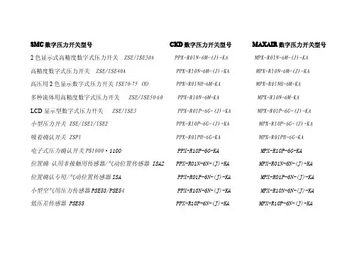
SMCKD D数字压力开关型号MAXAIMAXAIR R数字压力开关型号SMC C数字压力开关型号CK2色显示式高精度数字式压力开关ZSE/ISE30A PPX-R01N-6M-(J)-KA MPX-R01N-6M-(J)-KA高精度数字式压力开关ZSE/ISE40A PPX-R10N-6M-(J)-KA MPX-R10N-6M-(J)-KA高压用2色显示数字式压力开关ISE70·75(H)PPX-R01NH-6M-KA MPX-R01NH-6M-KA多种流体用高精度数字式压力开关ZSE/ISE50·60PPX-R10N-6M-KA MPX-R10N-6M-KALCD显示型数字式压力开关ZSE/ISE3PPX-R01P-6G-(J)-KA MPX-R01P-6G-(J)-KA小型压力开关ZSE/ISE1/ISE2PPX-R10P-6G-(J)-KA MPX-R10P-6G-(J)-KA吸着确认开关ZSP1PPX-R01PH-6G-KA MPX-R01PH-6G-KA电子式压力确认开关PS1000·1100PPX-R10P-6G-KA MPX-R10P-6G-KA位置确认用非接触用传感器/气动位置传感器ISA2PPX-R01N-6N-(J)-KA MPX-R01N-6N-(J)-KA位置确认专用/气动位置传感器ISA PPX-R01P-6N-(J)-KA MPX-R01P-6N-(J)-KA小型空气用压力传感器PSE53/PSE54PPX-R10N-6N-(J)-KA MPX-R10N-6N-(J)-KA低压差传感器PSE55PPX-R10P-6N-(J)-KA MPX-R10P-6N-(J)-KA通用流体用压力传感器PSE56PPX-R01NH-6N-KA MPX-R01NH-6N-KA 多通道数字式压力传感器的控制器PSE200PPX-R01PH-6N-KA MPX-R01PH-6N-KA 2色显示式数字压力传感器的控制器PSE300PPX-R10NH-6N-KA MPX-R10NH-6N-KA 有触点压力开关IS1000PPX-R10PH-6N-KA MPX-R10PH-6N-KA 气动用压力开关IS3000通用压力开关ISG真空用压力开关/膜片式ZSM1。
文件No.PS※※-OMS0006CN-G数字式压力开关ZSE20(F)ISE20安全注意事项2型式表示・型号体系8产品各部位名称及功能10用语说明11安装·设置14设置方法14配管方法16配线方法18设定概要[测量模式] 20 压力设定21 3步设定模式22 简易设定模式24功能选择模式26功能选择模式说明26出厂设定26 F0 单位切换功能28 F1 OUT1的设定29 F3 数字滤波器的设定32 F4 自动预设功能的设定33 F6 显示值微调的设定35 F10 子画面的设定36 F11 显示分辨率的设定41 F80 省电模式的设定42 F81 密码输入的设定43 F82 线名输入的设定45 F90 全功能的设定46 F98 输出确认48 F99 恢复出厂设置49其他设定50维护54忘记密码的场合54故障一览表55规格62规格表62外形尺寸图64安全注意事项此处所示的注意事项是为了确保您能安全正确地使用本产品,预先防止对您和他人造成危害和伤害而制定的。
这些注意事项,按照危害和损伤的大小及紧急程度分为「注意」「警告」「危险」三个等级。
无论哪个等级都是与安全相关的重要内容,所以除了遵守国际规格(ISO/IEC)、日本工业规格(JIS)*1)以及其他安全法规*2)外,这些内容也请务必遵守。*1) ISO 4414: Pneumatic fluid power -- General rules relating to systemsISO 4413: Hydraulic fluid power -- General rules relating to systemsIEC 60204-1: Safety of machinery -- Electrical equipment of machines (Part 1: General requirements)ISO 10218: Manipulating industrial robots-SafetyJIS B 8370: 空气压系统通则JIS B 8361: 油压系统通则JIS B 9960-1: 机械类的安全性-机械的电气装置(第1部:一般要求事项)JIS B 8433: 产业用操作机器人-安全性等*2) 劳动安全卫生法等注意误操作时,有人员受伤的风险以及物品破损的风险。警告误操作时,有人员受到重大伤害甚至死亡的风险。
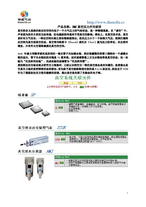
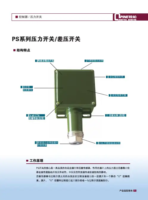
产品名称:SMC真空压力开关说明
真空的含义是指在给定的空间内低于一个大气压力的气体状态,是一种物理现象。
在“虚空”中,声音因为没有介质而无法传递,但电磁波的传递却不受真空的影响。
事实上,在真空技术里,真空系针对大气而言,一特定空间内部之部份物质被排出,使其压力小于一个标准大气压,则我们通称此空间为真空或真空状态。
真空常用帕斯卡(Pascal)或托尔(Torr)做为压力的单位。
在自然环境里,只有外太空堪称最接近真空的空间。
1641年意大利数学家托里拆利在一根长管子内加满水银,然后很缓慢的将管口倒转在一个盛满水银的盆内,管子内水银柱的末端是76厘米高。
这时玻璃管最上方无水银地带是真空状态。
这一实验为“托里拆利实验”,完成实验的玻璃管为“托里拆利管”。
爱因斯坦在用场论观点研究引力现象时,已经认识到空无一物的真空观念是有问题的,他曾提出真空是引力场的某种特殊状态的想法。
首先给予真空崭新物理内容的是P.A.M.狄拉克。
狄拉克于1930年为了摆脱狄拉克方程负能解的困境,提出真空是充满了负能态的电子海。
文件No.PS※※-OMM0006-A 使用说明书产 品 名 称数字式压力开关型式/系列/型号ZSE40A(F)ISE40A目录安全注意事项 2 型式表示・型号体系 9 产品各部品名称及功能 11 用语的定义及用语集 12 安装・设置 15 设置方法 15 配管方法 17 配线方法 19 压力设定 21 什么是设定模式 21 功能设定 23 什么是功能选择模式 23 出厂设定 23 F0 单位切换功能 25 F1 OUT1的设定 26 F2 OUT2的设定 29 F3 响应时间的设定 31 F4 自动预设功能的设定 32 F5 模拟输出/自动移位输入的设定 34 F6 显示值微调整的设定 36 F11 分辨率的设定 37 F80 省电模式的设定 38 F81密码输入的设定 39 特殊功能的设定 40 F90 全功能的设定 40 F97 复制功能的选择 42 F98 输出确认 44 F99 恢复出厂设置 46 其他设定 47 维护 50 忘记密码的情况 51 故障的消除 52 规格 59 规格表 59 外形尺寸图 61安全注意事项这里所示的注意事项是为了能安全正确的使用本产品,预先防止对您和他人造成危害或损失。
为了表示这些事项的危险程度,将注意事项分成「注意」「警告」和「危险」三个等级。
请您也遵守和安全相关的其他重要内容,如国际规格(ISO/IEC)、日本工业规格(JIS)※1以及其他安全法规※2。
*1) ISO 4414: Pneumatic fluid power -- General rules relating to systemsISO 4413: Hydraulic fluid power -- General rules relating to systemsIEC 60204-1: Safety of machinery -- Electrical equipment of machines (Part 1: General requirements) ISO 10218-1: Robots for industrial environments—Safety requirements –Part 1: RobotJIS B 8370: 空气压系统通则JIS B 8361: 油压系统通则JIS B 9960-1: 机械类的安全性-机械的电气装置(第1部:一般要求事项)JIS B 8433-1: 工业机器人- 安全要求事项-第1部: 机器人等*2) 劳动安全卫生法 等注意: 错误操作时,人和设备可能受到损伤的事项。
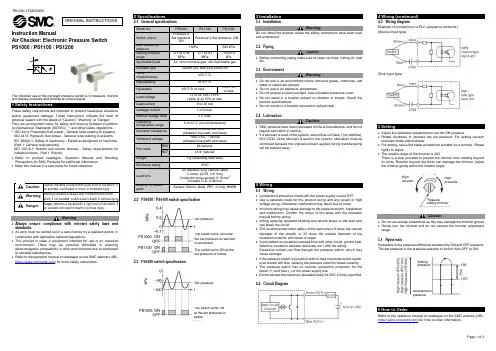
Instruction ManualAir Checker: Electronic Pressure Switch PS1000 / PS1100 / PS1200The intended use of the compact pressure switch is to measure, monitor and display pressure and provide an output signal.These safety instructions are intended to prevent hazardous situations and/or equipment damage. These instructions indicate the level of potential hazard with the labels of “Caution,” “Warning” or “Danger.”They are all important notes for safety and must be followed in addition to International Standards (ISO/IEC) *1), and other safety regulations. *1)ISO 4414: Pneumatic fluid power - General rules relating to systems. ISO 4413: Hydraulic fluid power - General rules relating to systems.IEC 60204-1: Safety of machinery - Electrical equipment of machines. (Part 1: General requirements)ISO 10218-1: Robots and robotic devices - Safety requirements for industrial robots - Part 1: Robots.• Refer to product catalogue, Operation Manual and Handling Precautions for SMC Products for additional information. • Keep this manual in a safe place for future reference.CautionCaution indicates a hazard with a low level of risk which, if not avoided, could result in minor or moderate injury.WarningWarning indicates a hazard with a medium level of riskwhich, if not avoided, could result in death or serious injury.DangerDanger indicates a hazard with a high level of risk which, ifnot avoided, will result in death or serious injury.Warning• Always ensure compliance with relevant safety laws and standards.• All work must be carried out in a safe manner by a qualified person in compliance with applicable national regulations.•This product is class A equipment intended for use in an industrialenvironment. There may be potential difficulties in ensuring electromagnetic compatibility in other environments due to conducted or radiated disturbances.• Refer to the operation manual or catalogue on the SMC website (URL: https:// ) for more safety instructions.2 Specifications2.1 General specifications2.2 PS1000 / PS1100 switch specification2.3 PS1200 switch specification3 Installation3.1 InstallationWarningDo not install the product unless the safety instructions have been read and understood.3.2 PipingCaution• Before connecting piping make sure to clean up chips, cutting oil, dust etc.3.3 EnvironmentWarning• Do not use in an environment where corrosive gases, chemicals, salt water or steam are present.• Do not use in an explosive atmosphere.• Do not expose to direct sunlight. Use a suitable protective cover.• Do not install in a location subject to vibration or impact. Check the product specifications.• Do not mount in a location exposed to radiant heat.3.4 LubricationCaution• SMC products have been lubricated for life at manufacture, and do not require lubrication in service.• If a lubricant is used in the system, use turbine oil Class 1 (no additive), ISO VG32. Once lubricant is used in the system, lubrication must be continued because the original lubricant applied during manufacturing will be washed away.4 Wiring4.1 Wiring• Connections should be made with the power supply turned OFF.• Use a separate route for the product wiring and any power or high voltage wiring. Otherwise, malfunction may result due to noise.• Incorrect wiring may cause damage to the pressure switch, breakdown and malfunction. Confirm the colour of the wires with the operation manual before wiring.• Wiring applying repeated bending and tensile stress to the lead wire can break the circuit.• The recommended bend radius of the lead wire is 6 times the outside diameter of the sheath, or 33 times the outside diameter of the insulation material, whichever is larger.• Avoid defective insulation (crossed lines with other circuit, ground fault, defective insulation between terminals, etc.) with the wiring.Excessive current can flow through the pressure switch, which may cause damage.• If the pressure switch is turned on with no load connected to the switch, over current will flow, causing the pressure switch to break instantly. • The pressure switch has no reverse connection protection for the brown (+) and blue (-) of the power supply line.• Do not exceed the maximum allowable load (24 VDC,40 mA) specified.4.2 Circuit Diagram4 Wiring (continued)4.3 Wiring diagramExample of connection to a PLC (sequence controller). (Source Input type)(Sink Input type)5 Setting• Adjust the calibration adjustment to set the ON pressure.• Rotate clockwise to increase the set pressure. For setting vacuum pressure rotate anticlockwise.• For setting, use a flat blade screwdriver suitable for a trimmer. Rotate lightly to adjust.• The rotation angle of the trimmer is 220°.There is a stop provided to prevent the trimmer from rotating beyond its limits. Rotation beyond the limits can damage the trimmer. Adjust the trimmer gently within the rotation angle.Caution• Do not use a large screwdriver as this may damage the trimmer groove. • Gently turn the trimmer and do not exceed the trimmer adjustment range.5.1 HysteresisHysteresis is the pressure difference between the ON and OFF pressure. The set pressure is the pressure selected to switch from OFF to ON.6 How to OrderRefer to the operation manual or catalogue on the SMC website (URL: https:// ) for How to order information.ORIGINAL INSTRUCTIONSModel No. PS1000PS1100PS1200Switch output Pressure ≥Set pressure: ONPressure ≤ Set pressure: ONMax. operating pressure 1 MPa500 kPa Setting pressure range-0.1 to 0.45 MPa-0.1 to 0.4 MPa-100 to 0 kPaApplicable fluidsAir, non-corrosive gas, non-flammable gasIndicator light Switch ON: Red LED turns ONTemp. characteristics ±3% F.S. Repeatability ±1% F.S.Hysteresis4% F.S. or less10% F.S. or lessLoad voltage 12 to 24 VDC ±10%, ripple (p-p) 10% or lessLoad current 5 to 40 mA Leakage current1 mA max. Internal voltage drop 5 V max.Operatingtemperature range 0 to 60°C (no condensation) Insulation resistance 2 MΩ or more at 500 VDC (between live parts and case)Withstand voltage 1000 VAC, 1 minute (between live parts and case)Port sizes R06 φ6 reducer R07φ1/4” reducer Weight5 g (excluding lead wire)Enclosure rating IP40Lead wireOil resistant vinyl cabtyre cable2 cores, φ2.55,3 m longConductor cross section 0.18 mm 2Insulator O.D. 0.96 mm Material of wetted partsSensor: Silicon, Body: PBT, O-ring: HNBRThe switch turns ON when the set pressure is reached or exceeded.The switch turns ON at the set pressure or below.Set pressureSet pressureThe switch turns ON at the set pressure or below.High vacuum High pressure Pressure setting trimmer Setting pressureAtmospheric pressureRefer to the operation manual or catalogue on the SMC website (URL:https://) for Outline Dimensions.8.1 General MaintenanceCaution•Not following proper maintenance procedures could cause the productto malfunction and lead to equipment damage.•If handled improperly, compressed air can be dangerous.•Maintenance of pneumatic systems should be performed only byqualified personnel.•Before performing maintenance, turn off the power supply and be sureto cut off the supply pressure. Confirm that the air is released toatmosphere.•After installation and maintenance, apply operating pressure andpower to the equipment and perform appropriate functional andleakage tests to make sure the equipment is installed correctly.•If any electrical connections are disturbed during maintenance, ensurethey are reconnected correctly and safety checks are carried out asrequired to ensure continued compliance with applicable nationalregulations.•Do not make any modification to the product.•Do not disassemble the product, unless required by installation ormaintenance instructions.•Perform regular maintenance and inspections.It may not be impossible to guarantee safety due to unexpectedmalfunction or erroneous operation. Perform regular inspections andconfirm normal operation.•Use a soft cloth to clean the pressure switch. For heavy stains, use acloth soaked with diluted neutral detergent and fully squeezed, thenwipe up the stains again with a dry cloth.9.1 Limited warranty and Disclaimer/Compliance RequirementsRefer to Handling Precautions for SMC Products.Caution•SMC products are not intended for use as instruments for legalmetrology.Measurement instruments that SMC manufactures or sells have notbeen qualified by type approval tests relevant to the metrology(measurement) laws of each country.Therefore, SMC products cannot be used for business or certificationordained by the metrology (measurement) laws of each country.This product shall not be disposed of as municipal waste. Check yourlocal regulations and guidelines to dispose of this product correctly, inorder to reduce the impact on human health and the environment.Refer to or www.smc.eu for your local distributor /importer.URL: https:// (Global) https://www.smc.eu (Europe)SMC Corporation, 4-14-1, Sotokanda, Chiyoda-ku, Tokyo 101-0021, JapanSpecifications are subject to change without prior notice from the manufacturer.© 2021 SMC Corporation All Rights Reserved.Template DKP50047-F-085M。
ISE40-01-62L-M如何设定一.初始设定1.按“SET”键2S以上,直到显示“1no”。
当“1no”时开。
2.按“△”或“▽”选择out1输出模式。
(“1no”常开“1nc”常闭)设:1no3按“SET”键,再按“△”或“▽”选择out2输出模式。
(“2no ”常开,“2nc”常闭)设:2no4.按“SET”键,再按“△”或“▽”选择响应时间。
(“2.5”=2.5ms,“24”=24ms.“192=192ms”. “768”=768ms)在它们中间选一。
设:245.按“SET”键,再按“△”或“▽”选择“自动预置模式”或“手动预置模式”。
(“Aut”=自动预置模式,“nAn”=手动预置模式,设:nAn6.按“SET”键设定完毕。
二.手动压力设定1.手动设定模式在初始模式设定下,选择手动预置模式,并且按“SET”键,直到显示“P_1”(如上面选“1nc”,对应是“n_1”)。
2.输入out1⑴的设定点的值按“△”增加设定值,按“▽”减少设定值。
交替显示“P_1”和设定值,按“SET”键确认。
设:3(低压)3.输入out1⑵的设定点的值按“△”增加设定值,按“▽”减少设定值。
交替显示“P_2”和设定值,按“SET”键确认。
设:3(低压)4.输入out2⑴的设定点的值按“△”增加设定值,按“▽”减少设定值。
交替显示“P_3”和设定值,按“SET”键确认。
设:3.6(高压)5.输入out2⑵的设定点的值按“△”增加设定值,按“▽”减少设定值。
交替显示“P_4”和设定值,按“SET”键确认。
设:3.6(高压)三.单位设定1.按“△”键或按“▽”键,设定单位PR=KP或MP bRr=bar GF=Kg/c㎡inN=inHg PS=PS1nn=mmHg,按“SET”键确认。
四.上锁模式1.按住“SET”键或更长,当显示UnL时释放,按“△”键或按“▽”键,显示“LoC,”按“SET”键完成。
反之就是解锁。
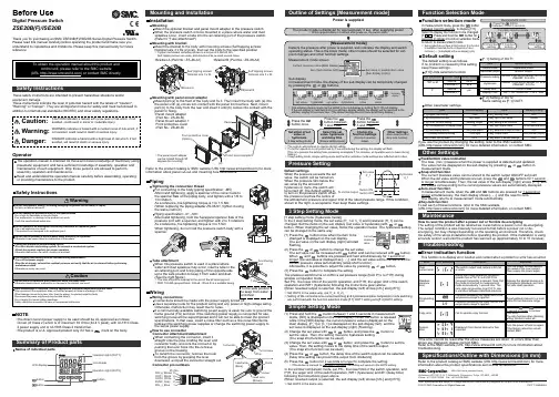
Other SettingsSummary of Product partsSimple Setting ModeTroubleshootingNote: Specifications are subject to change without prior notice and any obligation on the part of the manufacturer.© 2017 SMC Corporation All Rights ReservedAkihabara UDX 15F, 4-14-1, Sotokanda, Chiyoda-ku, Tokyo 101-0021, JAPANPhone: +81 3-5207-8249 Fax: +81 3-5298-5362URL Specifications/Outline with Dimensions (in mm)Refer to the product catalog or SMC website (URL ) for moreinformation about the product specifications and outline dimensions.PS※※-OMU0004 InstallationMountingMount the optional bracket and panel mount adapter to the pressure switch.When the pressure switch is to be mounted in a place where water and dustsplashes occur, insert a tube into the air-relieving port of the pressure switch.(Refer to "Tube attachment")Mounting with bracketMount the bracket to the body with mounting screws (Self tapping screws:Nominal size 3 x 8L (2 pcs)), then set the body to the specified position.∗: Tighten the bracket mounting screws to a torque of 0.5±0.05 Nm.Self tapping screws are used, and should not be re-used several times.∗: The panel mount adaptercan be rotated through 90degrees for mounting.•Bracket A (Part No.: ZS-46-A1)•Bracket B (Part No.: ZS-46-A2)Mounting with panel mount adapterMount part (a) to the front of the body and fix it. Then insert the body with (a) intothe panel until (a) comes into contact with the panel front surface. Next, mountpanel for fixing.•Panel mount adapter(Part No.: ZS-46-B)Panel mount adapter +Front protective cover(Part No.: ZS-46-D)WiringWiring connectionsUse a separate route for the product wiring and any power or high voltage wiring.Otherwise, malfunction may result due to noise.If a commercially available switching power supply is used, be sure to ground theframe ground (FG) terminal. If the switching power supply is connected for use,switching noise will be superimposed and it will not be able to meet the productspecifications. In that case, insert a noise filter such as a line noise filter/ferritebetween the switching power supplies or change the switching power supply tothe series power supply.How to use connectorConnector attachment/detachmentWhen connecting the connector, insert itstraight onto the pins, holding the lever andconnector body, and lock the connector bypushing the lever hook into the concavegroove on the housing.To detach the connector, remove the hookfrom the groove by pressing the leverdownward, and pull the connector straight out.DC(+)OUT1OUT2FUNCDC(-)BrownBlackWhiteGrayBluePipingTightening the connection threadFor connecting to the body (piping specification: -M5)After hand tightening, apply a spanner of the correct size tothe spanner flats of the piping body, and tighten with a 1/6 to1/4 rotation.As a reference, the tightening torque is 1 to 1.5 Nm.(When replacing the piping adapter ZS-46-N∗, tighten it usingthe same method.)Piping specification: -01, -N01After hand tightening, hold the hexagonal spanner flats of thepressure port with a spanner, and tighten with 2 to 3 rotations.As a reference, the tightening torque is 3 to 5 Nm.When tightening, do not hold the pressure switch body with aDefault settingsWhen the pressure exceeds the setvalue, the switch will be turned on.When the pressure falls below theset value by the amount ofhysteresis or more, the switch willbe turned off. The default setting isto turn on the pressure switch whenthe pressure reaches the centre ofthe atmospheric pressure and upper limit of the rated pressure range. If this condition,shown to the right, is acceptable, then keep these settings.Error indication functionThis function is to display error location and content when a problem or error has occurred.above are displayed, please contact SMC.Refer to the SMC website (URL ) for more information abouttroubleshooting.Power is supplied.button between1 and 3 sec.∗:The outputs will continue to operate during setting.∗:If a button operation is not performed for 3 seconds during the setting, the display will flash.(This is to prevent the setting from remaining incomplete if, for instance, an operator were to leave duringsetting.)∗:3 step setting mode, simple setting mode and function selection mode settings are reflected each other.[3 step setting mode (hysteresis mode)]orcan be changed in the same way.button once when the item to beThe set value on the sub display (right) will startflashing.orbutton.buttons are pressed and held simultaneously for 1 second orlonger, the set value is displayed as [- - -], and the set value will be the same as thecurrent pressure value automatically (snap shot function).Afterwards, it is possible to adjust the value by pressing button.button to complete the setting.The pressure switch turns on within a set pressure range (from P1L to P1H) duringwindow comparator mode.Set P1L, the lower limit of the switch operation, and P1H, the upper limit of the switchoperation and WH1 (hysteresis) following the instructions given above.(When reversed output is selected, the sub display (left) shows [n1L] and [n1H].)∗:Set OUT2 in the same way. (ex. P_2, H_2)∗:Setting of the normal/reverse output switching and hysteresis/window comparator mode switchingare performed with the function selection mode [F 1] OUT1 setting and [F 2] OUT2 setting.value[F 0] Units selection functionPeak/bottom value indicationbutton inmeasurement mode.Snap shot functionbuttons for 1 secondor longer simultaneously. Then, the set value of the sub display (right) shows [- - -], andthe values corresponding to the current pressure values are automatically displayed.Zero-clear functionbuttons are pressed for 1 second orlonger simultaneously, the main display shows [- - -], and the reset to zero.The display returns to measurement mode automatically.Key-lock functionTo set each of these functions, refer to the SMC website(URL ) for more detailed information, or contact SMC.button between 1 and 3 seconds in measurementmode. [SEt] is displayed on the main display. When the button is releasedwhile in the [SEt] display, the current pressure value is displayed on themain display, [P_1] or [n_1] is displayed on the sub display (left), and theset value is displayed on the sub display (right) (Flashing).or button to(The snap shot function can be used.)or button to set the(The snap shot function can be used.)or button, the delay time of the switch output can be selected.button for 2 seconds or longer to complete the setting.∗:If the button is pressed for less than 2 seconds, the setting will moves to the OUT2 setting.In the window comparator mode, set P1L, the lower limit of the switch operation, andP1H, the upper limit of the switch operation, WH1 (hysteresis) and dt1 (delay time)following the instructions given above.(When reversed output is selected, the sub display (left) shows [n1L] and [n1H].)∗:Set OUT2 in the same way.Function selection modebuttonbetween 3 and 5 seconds, to display [F 0].Select to display the function to be changed[F button for 2seconds or longer in function selection modeto return to measurement mode.∗:Some products do not have all the functions. If no functionis available or selected due to configuration of otherfunctions, [- - -] is displayed on the sub display (right).Names of individual partsRefer to the product catalog or SMC website (URL ) for moreinformation about panel cut-out and mounting hole dimensions.Pressure Setting3 Step Setting Mode(URL ) for more detailed information, or contact SMC.MaintenanceHow to reset the product after a power cut or forcible de-energizingThe setting of the product will be retained as it was before a power cut or de-energizing.The output condition is also basically recovered to that before a power cut or de-energizing, but may change depending on the operating environment. Therefore, checkthe safety of the whole installation before operating the product. If the installation is usingaccurate control, wait until the product has warmed up (approximately 10 to 15 minutes). Safety InstructionsBefore UseDigital Pressure SwitchZSE20B(F)/ISE20BThank you for purchasing an SMC ZSE20B(F)/ISE20B Series Digital Pressure Switch.Please read this manual carefully before operating the product and make sure youunderstand its capabilities and limitations. Please keep this manual handy for futurereference.Safety InstructionsThese safety instructions are intended to prevent hazardous situations and/orequipment damage.These instructions indicate the level of potential hazard with the labels of "Caution","Warning" or "Danger". They are all important notes for safety and must be followed inaddition to International standards (ISO/IEC) and other safety regulations.OperatorSwitch ONAt normal output Switch OFFSet valueP_1HysteresisH_1TimePressureDefault settingThe default setting is as follows.If no problem is caused by this setting,keep these settings.Connector pin numbers[F 2] Setting of OUT2Same setting as [F 1] OUT1.NOTE•The direct current power supply to be used should be UL approved as follows:Circuit (of Class 2) which is of maximum 30 Vrms (42.4 V peak), with UL1310 Class2 power supply unit or UL1585 Class 2 transformer.•The product is a UL approved product only if it has a mark on the body.Tube attachmentWhen this pressure switch is used in a place wherewater and dust splashes may occur, insert a tube in theair-relieving port, and bring piping of the opposite sideup to the safe position to keep it from water and dust.(See the right figure.)∗: The tube should be inserted to the end of the air-relieving port.∗: SMC TU0425 (polyurethane, O.D ø4, I.D ø2.5) is a suitable tubing.。
SMC压力开关设定ISE40-01-62L-M如何设定一.初始设定1.按“SET”键2S以上,直到显示“1no”。
当“1no”时开。
2.按“△”或“▽”选择out1输出模式。
(“1no”常开“1nc”常闭)设:1no3 按“SET”键,再按“△”或“▽”选择out2输出模式。
(“2no ”常开,“2nc”常闭)设:2no4.按“SET”键,再按“△”或“▽”选择响应时间。
(“2.5”=2.5ms,“24”=24ms.“192=192ms”. “768”=768ms)在它们中间选一。
设:245. 按“SET”键,再按“△”或“▽”选择“自动预置模式”或“手动预置模式”。
(“Aut”=自动预置模式,“nAn”=手动预置模式,设:nAn6.按“SET”键设定完毕。
二.手动压力设定1.手动设定模式在初始模式设定下,选择手动预置模式,并且按“SET”键,直到显示“P_1”(如上面选“1nc”,对应是“n_1”)。
2.输入out1⑴的设定点的值按“△”增加设定值,按“▽”减少设定值。
交替显示“P_1”和设定值,按“SET”键确认。
设:3(低压)3.输入out1⑵的设定点的值按“△”增加设定值,按“▽”减少设定值。
交替显示“P_2”和设定值,按“SET”键确认。
设:3(低压)4.输入out2⑴的设定点的值按“△”增加设定值,按“▽”减少设定值。
交替显示“P_3”和设定值,按“SET”键确认。
设:3.6(高压)5.输入out2⑵的设定点的值按“△”增加设定值,按“▽”减少设定值。
交替显示“P_4 ”和设定值,按“SET”键确认。
设:3.6(高压)三.单位设定1.按“△”键或按“▽”键,设定单位PR=KP或MP bRr=bar GF=Kg/c㎡inN=inHg PS=PS1 nn=mmHg,按“SET”键确认。
四.上锁模式1.按住“SET”键或更长,当显示UnL时释放,按“△”键或按“▽”键,显示“LoC,”按“SET”键完成。
SMC压力开关如何调试?发表于:2019年07月30日17:02转发0针对我司客户对SMC压力开关的调试问题,我们做出了以下总结:问题一、客户:ZSE40F设置1no,2no时,当P1:-7.9,P2:-10.8,P3:-93.8,P4:-100时,信号灯输出混乱,请教是设置原因或产品质量问题?欧迅自动化设备回答:1:对于ZSE40F来说,当设置1no,2no时,在压力输出范围内红绿输出信号灯要亮. 2:压力值输出数值设置一般要求:P1﹤P2﹤P3﹤P4。
压力在P1至P2范围内绿灯亮,压力在P3至P4范围内红灯亮,相应的信号灯在范围外不亮。
3:你的开关应设置成P1:-100,P2:-93.8,P3:-10.8,P4:-7.9,相应设置1no,2no,若真空值为-95.0Kpa(P1:-100~P2:-93.8之间)左右时绿灯亮,这时红灯不会亮,若真空值为-9.0Kpa(P1:-10.8~P2:-7.9之间)左右时红灯亮,这时绿灯不会亮,若压力值在这两者各自的范围外,则信号灯输出恰恰相反。
4:你的压力值要这样设置,建议你使用真空压ZSE40(范围-101.3~10)更合适.问题二、客户:请教当ZSE40F设置成1nc,2nc时,是否信号灯就不亮?欧迅自动化设备简单的回答:设置1nc,2nc仅仅表示在设置范围内的输出灯不亮,在范围外的灯照样亮.问题三、客户:请教ZSE40的信号灯设置怎么与ZSE40F不一样,应如何设置?欧迅自动化设备简单的回答:1.压力开关ZSE40F,ISE40相对应的1no,2no为常开,1nc,2nc为常闭;压力开关ZSE40(真空压)相对应的1no,2no为常闭,1nc,2nc为常开。
2:当设置成1nc,2nc时出现的为n1,n2,n3,n4,这时要求n1﹤n2﹤n3﹤n4,这时压力值在相对应的范围内会亮。
3:ZSE40(真空压)在n1和n4临界点的输出信号也不一样。
附一:SMC压力开关的使用一:使用环境1:适合流体:空气、非腐蚀性气体;2:使用温度:保存时0~50℃,工作时10~50℃。
SMC压力开关如何调试SMC压力开关如何调试?发表于:2019年07月30日17:02转发0针对我司客户对SMC压力开关的调试问题,我们做出了以下总结:问题一、客户:ZSE40F设置1no,2no时,当P1:-7.9,P2:-10.8,P3:-93.8,P4:-100时,信号灯输出混乱,请教是设置原因或产品质量问题?欧迅自动化设备回答:1:对于ZSE40F来说,当设置1no,2no时,在压力输出范围内红绿输出信号灯要亮. 2:压力值输出数值设置一般要求:P1﹤P2﹤P3﹤P4。
压力在P1至P2范围内绿灯亮,压力在P3至P4范围内红灯亮,相应的信号灯在范围外不亮。
3:你的开关应设置成P1:-100,P2:-93.8,P3:-10.8,P4:-7.9,相应设置1no,2no,若真空值为-95.0Kpa(P1:-100~P2:-93.8之间)左右时绿灯亮,这时红灯不会亮,若真空值为-9.0Kpa(P1:-10.8~P2:-7.9之间)左右时红灯亮,这时绿灯不会亮,若压力值在这两者各自的范围外,则信号灯输出恰恰相反。
4:你的压力值要这样设置,建议你使用真空压ZSE40(范围-101.3~10)更合适.问题二、客户:请教当ZSE40F设置成1nc,2nc时,是否信号灯就不亮?欧迅自动化设备简单的回答:设置1nc,2nc仅仅表示在设置范围内的输出灯不亮,在范围外的灯照样亮.问题三、客户:请教ZSE40的信号灯设置怎么与ZSE40F不一样,应如何设置?欧迅自动化设备简单的回答:1.压力开关ZSE40F,ISE40相对应的1no,2no为常开,1nc,2nc为常闭;压力开关ZSE40(真空压)相对应的1no,2no为常闭,1nc,2nc为常开。
2:当设置成1nc,2nc 时出现的为n1,n2,n3,n4,这时要求n1﹤n2﹤n3﹤n4,这时压力值在相对应的范围内会亮。
3:ZSE40(真空压)在n1和n4临界点的输出信号也不一样。
SMC压力开关如何调试?发表于:2019 年07 月30日17:02 转发0针对我司客户对SMC压力开关的调试问题,我们做出了以下总结:问题一、客户:ZSE40F设置1no,2no 时,当P1:-7.9,P2:-10.8,P3:-93.8,P4:-100 时,信号灯输出混乱,请教是设置原因或产品质量问题?欧迅自动化设备回答:1:对于ZSE40F来说,当设置1no,2no时,在压力输出范围内红绿输出信号灯要亮• 2:压力值输出数值设置一般要求:P1 < P2< P3< P4。
压力在P1至P2范围内绿灯亮,压力在P3至P4范围内红灯亮,相应的信号灯在范围外不亮。
3:你的开关应设置成P1:-100,P2:-93.8,P3:-10.8,P4:-7.9, 相应设置1no, 2no,若真空值为-95.0Kpa(P1:-100〜P2:-93.8之间)左右时绿灯亮,这时红灯不会亮,若真空值为- 9.0Kpa(P1:-10.8〜P2:-7.9之间)左右时红灯亮,这时绿灯不会亮,若压力值在这两者各自的范围外,则信号灯输出恰恰相反。
4:你的压力值要这样设置,建议你使用真空压ZSE40(范围-101.3〜10)更合适.问题二、客户:请教当ZSE40F设置成1nc, 2nc时,是否信号灯就不亮?欧迅自动化设备简单的回答:设置1nc,2nc 仅仅表示在设置范围内的输出灯不亮,在范围外的灯照样亮.问题三、客户:请教ZSE40的信号灯设置怎么与ZSE4OF不一样,应如何设置?欧迅自动化设备简单的回答:1.压力开关ZSE40F,ISE40相对应的1no,2no为常开,1 nc,2nc 为常闭;压力开关ZSE40滇空压)相对应的1no,2no 为常闭,1nc,2nc 为常开。
2:当设置成1nc,2nc 时出现的为n1,n2,n3,n4,这时要求n1< n2< n3< n4,这时压力值在相对应的范围内会亮。
SMC压力传感器的详细资料 @日本SMC传感器、压力开关压力传感器是工业实践中最为常用的一种传感器。
一般普通压力传感器的输出为模拟信号,模拟信号是指信息参数在给定范围内表现为连续的信号。
或在一段连续的时间间隔内,其代表信息的特征量可以在任意瞬间呈现为任意数值的信号。
而通常使用的压力传感器主要是利用压电效应制造而成的,这样的传感器也称为压电传感器。
压力传感器是使用最为广泛的一种传感器。
传统的压力传感器以机械结构型的器件为主,以弹性元件的形变指示压力,但这种结构尺寸大、质量重,不能提供电学输出。
随着半导体技术的发展,半导体压力传感器也应运而生。
其特点是体积小、质量轻、准确度高、温度特性好。
特别是随着MEMS技术的发展,半导体传感器向着微型化发展,而且其功耗小、可靠性高。
1 PSE510-R06 一般气体用,使用压力范围0 - 1MPa,φ6快接管2 PSE511-R06 一般气体用,使用压力范围 - 101 - 0KPa,φ6快接管3 PSE512-R06 一般气体用,使用压力范围0 - 100Ka,φ6快接管4 PSE510-M5 一般气体用,使用压力范围0 - 1MPa,M5螺纹接口5 PSE511-M5 一般气体用,使用压力范围 - 101 - 0KPa,M5螺纹接口6 PSE512-M5 一般气体用,使用压力范围0 - 100Ka,M5螺纹接口7 PSE510-01 一般气体用,使用压力范围0 - 1MPa,1/8螺纹接口8 PSE511-01 一般气体用,使用压力范围 - 101 - 0KPa,1/8螺纹接口9 PSE512-01 一般气体用,使用压力范围0 - 100Ka,1/8螺纹接口SMC压力传感器的详细资料 @日本SMC传感器、压力开关10 PSE530-M5 一般气体用,适用于高压环境,M5螺纹接口11 PSE531-M5 一般气体用,适用于真空环境,M5螺纹接口12 PSE532-M5 一般气体用,适用于低压环境,M5螺纹接口13 PSE533-M5 一般气体用,适用于复合压环境,M5螺纹接口14 PSE530-R06 一般气体用,适用于高压环境,φ6减径插杆15 PSE531-R06 一般气体用,适用于真空环境,φ6减径插杆16 PSE532-R06 一般气体用,适用于低压环境,φ6减径插杆17 PSE533-R06 一般气体用,适用于复合压环境,φ6减径插杆18 PSE530-R07 一般气体用,适用于高压环境,1/4减径插杆19 PSE531-R07 一般气体用,适用于真空环境,1/4减径插杆20 PSE532-R07 一般气体用,适用于低压环境,1/4减径插杆21 PSE533-R07 一般气体用,适用于复合压环境,1/4减径插杆液位压力传感器压力传感器的种类繁多,其性能也有较大的差异,如何选择较为适用的传感器,做到经济、合理的使用。