供应流体用数显压力开关(SMC型)ZSE40F-01-22L
- 格式:pdf
- 大小:176.31 KB
- 文档页数:4
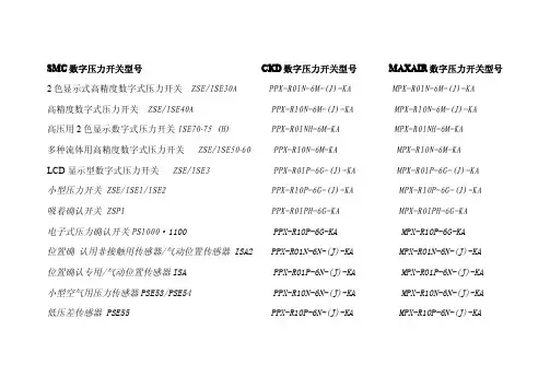
SMCKD D数字压力开关型号MAXAIMAXAIR R数字压力开关型号SMC C数字压力开关型号CK2色显示式高精度数字式压力开关ZSE/ISE30A PPX-R01N-6M-(J)-KA MPX-R01N-6M-(J)-KA高精度数字式压力开关ZSE/ISE40A PPX-R10N-6M-(J)-KA MPX-R10N-6M-(J)-KA高压用2色显示数字式压力开关ISE70·75(H)PPX-R01NH-6M-KA MPX-R01NH-6M-KA多种流体用高精度数字式压力开关ZSE/ISE50·60PPX-R10N-6M-KA MPX-R10N-6M-KALCD显示型数字式压力开关ZSE/ISE3PPX-R01P-6G-(J)-KA MPX-R01P-6G-(J)-KA小型压力开关ZSE/ISE1/ISE2PPX-R10P-6G-(J)-KA MPX-R10P-6G-(J)-KA吸着确认开关ZSP1PPX-R01PH-6G-KA MPX-R01PH-6G-KA电子式压力确认开关PS1000·1100PPX-R10P-6G-KA MPX-R10P-6G-KA位置确认用非接触用传感器/气动位置传感器ISA2PPX-R01N-6N-(J)-KA MPX-R01N-6N-(J)-KA位置确认专用/气动位置传感器ISA PPX-R01P-6N-(J)-KA MPX-R01P-6N-(J)-KA小型空气用压力传感器PSE53/PSE54PPX-R10N-6N-(J)-KA MPX-R10N-6N-(J)-KA低压差传感器PSE55PPX-R10P-6N-(J)-KA MPX-R10P-6N-(J)-KA通用流体用压力传感器PSE56PPX-R01NH-6N-KA MPX-R01NH-6N-KA 多通道数字式压力传感器的控制器PSE200PPX-R01PH-6N-KA MPX-R01PH-6N-KA 2色显示式数字压力传感器的控制器PSE300PPX-R10NH-6N-KA MPX-R10NH-6N-KA 有触点压力开关IS1000PPX-R10PH-6N-KA MPX-R10PH-6N-KA 气动用压力开关IS3000通用压力开关ISG真空用压力开关/膜片式ZSM1。
文件No.PS※※-OMS0006CN-G数字式压力开关ZSE20(F)ISE20安全注意事项2型式表示・型号体系8产品各部位名称及功能10用语说明11安装·设置14设置方法14配管方法16配线方法18设定概要[测量模式] 20 压力设定21 3步设定模式22 简易设定模式24功能选择模式26功能选择模式说明26出厂设定26 F0 单位切换功能28 F1 OUT1的设定29 F3 数字滤波器的设定32 F4 自动预设功能的设定33 F6 显示值微调的设定35 F10 子画面的设定36 F11 显示分辨率的设定41 F80 省电模式的设定42 F81 密码输入的设定43 F82 线名输入的设定45 F90 全功能的设定46 F98 输出确认48 F99 恢复出厂设置49其他设定50维护54忘记密码的场合54故障一览表55规格62规格表62外形尺寸图64安全注意事项此处所示的注意事项是为了确保您能安全正确地使用本产品,预先防止对您和他人造成危害和伤害而制定的。
这些注意事项,按照危害和损伤的大小及紧急程度分为「注意」「警告」「危险」三个等级。
无论哪个等级都是与安全相关的重要内容,所以除了遵守国际规格(ISO/IEC)、日本工业规格(JIS)*1)以及其他安全法规*2)外,这些内容也请务必遵守。*1) ISO 4414: Pneumatic fluid power -- General rules relating to systemsISO 4413: Hydraulic fluid power -- General rules relating to systemsIEC 60204-1: Safety of machinery -- Electrical equipment of machines (Part 1: General requirements)ISO 10218: Manipulating industrial robots-SafetyJIS B 8370: 空气压系统通则JIS B 8361: 油压系统通则JIS B 9960-1: 机械类的安全性-机械的电气装置(第1部:一般要求事项)JIS B 8433: 产业用操作机器人-安全性等*2) 劳动安全卫生法等注意误操作时,有人员受伤的风险以及物品破损的风险。警告误操作时,有人员受到重大伤害甚至死亡的风险。
Digital Pressure SwitchOperation ManualZSE40A(F)/ISE40AThank you for purchasing the SMC ZSE40A(F)/ISE40A Series Digital Pressure Switch.Please read this manual carefully before operating the digital pressure switch and make sure you understand the digital pressure switch, its capabilities and limitations.Please keep this manual handy for future reference.To get information in detail for operating this product, refer to SMC website (URL ) or contact us.Indication light (Orange LED): Displays the switch operation condition.LCD display: Displays the current status of pressure, setting mode and error code.Four display modes can be selected to display always in red orgreen only, or changing from green to red, red to green according to the output status.button (UP): Selects the mode or increases the ON/OFF set value.Press this button to change to the peak display mode.button (DOWN): Selects the mode or decreases the ON/OFF set value.Press this button to change to the bottom display mode.button (SET): Press this button to change to either mode and to set a value.These safety instructions are intended to prevent hazardous situations and/or equipment damage.These instructions indicate the level of potential hazard with the labels of"Caution", " Warning" or "Danger". They are all important notes for safety and must be followed in addition to International standards (ISO/IEC), Japan Industrial Standards (JIS) and other safety regulations.OperatorInstallationMountingMount the optional bracket and panel mount adapter to the pressure switch.When the pressure switch is to be mounted in a place where water and dust splashes occur, insert a tube into the air-relieving port of the pressure switch.(Refer to "Tube attachment")Mounting with bracketFix the bracket to the pressure switch with the set screws M3x5L (2 pcs.) or M4x5L (2 pcs.) supplied.Apply a tightening torque of 0.5 to 0.7 Nm for the M3 set screws or 1.4 to 1.6 Nm for the M4 set screws .WiringConnection Make connection after turning the power e a separate route when connecting the wire ofthe Pressure switch.Malfunction stemming from noise may occur if the wire is installed in the same route as that of power or high-voltage cable.Be sure to ground terminal FG when using a commerically available switch-mode power supply.When the switch-mode power supply is connected to the Pressure switch,switching noise wil be superimposed and product specification can no longer be met. This can be prevented by inserting a noise filter, such as a line noise filter and ferrite core, between the switch-mode power supply and the Pressure switch, or by using a series power supply instead of the switch-mode power supply.Names of individual partsSet ON point and OFF point of the Pressure switch.Operation When the pressure exceeds a set value, the Pressure switch will be turned on.When the pressure falls below the set value by the amount of hysteresis or more, the Pressure switch will be turned off.The default setting of the output set value is the central value between the atmospheric pressure and the upper limit of the rated pressure range. If theoperation shown the right does not cause any problem, keep this operation setting.Switch ONP_1H_1Time [s]P r e s s u r e [P a ]<How to operate>button once in measurement mode.(2)[P_1] or [n_1] and set value are displayed in turn.Normal output Reversed outputbutton once to increase by one figure, and press it continuously to keep button once to decrease by one button to finish the setting of OUT1.[ Window comparator mode ]The Pressure switch turns on within a set pressure range (from P1L to P1H)during window comparator mode. Set P1L (switch lower limit) and P1H (switch At the time of shipment, the following settings are provided.If the setting is acceptable, keep it for use.To change setting, refer to SMC website (URL ) to get information in detail or contact us.[F 0] Unit conversion functionSame setting as [F 1] OUT1.At the output mode, Error detection mode can be selected.Display color is linked to the setting of OUT1, and can not be selected.Other parameter settingMeasurement modeThe measurement mode is the condition where the pressure is detected and indicated, and the switch function is operating.This is the basic mode, and other modes should be selected for setting change and other function setting changes.Function selection modeMeasurement modePeak/Bottom hold value indication Zero clear Key lockTo set each function the above in detail, refer to SMC website (URL ) to get information in detail or contact us.MaintenanceHow to reset the product after power cut or forcible de-energizing The setting of the product will be retained as it was before a power cut or de-energizing.The output condition is also basically recovered to that before a power cut or de-energizing, but may change depending on the operating environment.Therefore, check the safety of the whole facility before operating the product. If the facility is using accurate control, wait until the pressure switch has warmed up.(About 10 to 15 minutes)∗:Some functions are not available depending on part number. All functions are displayed with[F ] and followed with function description. If a function is not available for specified type, the function is displayed as [---].TroubleshootingError indication functionThis function is to display error location and content when a problem or an error occurs.SpecificationRefer to the product catalogue or SMC website (URL ) to get information about product specifications in detail.Outline with Dimensions (in mm)Refer to the product catalogue or SMC website (URL ) to get information about outline dimensions in detail.Akihabara UDX 15F, 4-14-1, Sotokanda, Chiyoda-ku, Tokyo 101-0021, JAPAN Phone: +81 3-5207-8249 Fax: +81 3-5298-5362URL Note: Specifications are subject to change without prior notice and any obligation on the part of the manufacturer.© 2009 SMC Corporation All Rights Reserved•Bracket A or D(Model: ZS-24-A/ZS-24-D)•Bracket B (Model: ZS-24-B)[01/N01 type][W1/WF1 type]button for 2[F 0]. Select to display the function setting to be changed, [F ].button for 2selection mode to return tomeasurement mode.。
产品名称:SMC zse40f-01-22l-m资料SMCCORPORATION成立于1959年,总部设在日本东京都。
时至今日,SMC已成为世界级的气动元件研发、制造、销售商。
在日本本土更拥有庞大的市场网络,为客户提供产品及售后服务。
SMC 作为世界最著名的气动元件制造和销售的跨国公司,其销售网及生产基地遍布世界。
SMC产品以其品种齐全、可靠性高、经济耐用、能满足众多领域不同用户的需求而闻名于世。
在日本市场占有率已超过60%的SMC,通过分布于世界51个国家的海外子公司及分销商,将世界各国SMC产品的生产、销售连成一体,为用户提供直接、完善的服务。
SMCKD D数字压力开关型号MAXAIMAXAIR R数字压力开关型号SMC C数字压力开关型号CK2色显示式高精度数字式压力开关ZSE/ISE30A PPX-R01N-6M-(J)-KA MPX-R01N-6M-(J)-KA高精度数字式压力开关ZSE/ISE40A PPX-R10N-6M-(J)-KA MPX-R10N-6M-(J)-KA高压用2色显示数字式压力开关ISE70·75(H)PPX-R01NH-6M-KA MPX-R01NH-6M-KA多种流体用高精度数字式压力开关ZSE/ISE50·60PPX-R10N-6M-KA MPX-R10N-6M-KALCD显示型数字式压力开关ZSE/ISE3PPX-R01P-6G-(J)-KA MPX-R01P-6G-(J)-KA小型压力开关ZSE/ISE1/ISE2PPX-R10P-6G-(J)-KA MPX-R10P-6G-(J)-KA吸着确认开关ZSP1PPX-R01PH-6G-KA MPX-R01PH-6G-KA电子式压力确认开关PS1000·1100PPX-R10P-6G-KA MPX-R10P-6G-KA位置确认用非接触用传感器/气动位置传感器ISA2PPX-R01N-6N-(J)-KA MPX-R01N-6N-(J)-KA位置确认专用/气动位置传感器ISA PPX-R01P-6N-(J)-KA MPX-R01P-6N-(J)-KA小型空气用压力传感器PSE53/PSE54PPX-R10N-6N-(J)-KA MPX-R10N-6N-(J)-KA低压差传感器PSE55PPX-R10P-6N-(J)-KA MPX-R10P-6N-(J)-KA通用流体用压力传感器PSE56PPX-R01NH-6N-KA MPX-R01NH-6N-KA 多通道数字式压力传感器的控制器PSE200PPX-R01PH-6N-KA MPX-R01PH-6N-KA 2色显示式数字压力传感器的控制器PSE300PPX-R10NH-6N-KA MPX-R10NH-6N-KA 有触点压力开关IS1000PPX-R10PH-6N-KA MPX-R10PH-6N-KA 气动用压力开关IS3000通用压力开关ISG真空用压力开关/膜片式ZSM1。

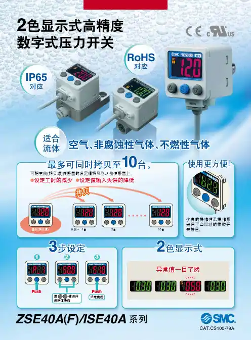
空气压用数字式压力开关Z/ISE30A Series
气动元件论坛 整理上传
1.特征 Copy功能-最多可以将开关设定同时复制至10台
追加2路开关输出
2路开关输出(NPN2路 PNP2路)
1路开关输出+模拟输出(准标准)
1.特征 真空范围追加(0.0~-101.0kPa)
4位显示
显示精度调整功能
MPa-KPa切换功能
标准对应C E,UL/CSA,RoHS
1.特征 键盘锁定模式下可查看设定值
键盘锁定追加密码锁
追加省电模式
标准对应C E,UL/CSA,RoHS
2.开发目的 将原有产品(Z/ISE30系列)的功能强化,进一步推进传感器扩销。
9.使用上注意点 请在通电4秒后,使用本压力开关进行压力检测。
通电后4秒内,开关输出一直为OFF状态。
请注意检测管路中如果有异物或水分会造成压力开关的破损。
请不要在有水、油及药液飞溅的场所使用本压力开关。
10.总结(「卖点」)
追加多种辅助功能
追加2路输出规格
开关输出2路(NPN2路输出 PNP2路输出)
开关输出1路+模拟输出(准标准)
(可以适用于现在使用Z/ISE40,而实际不需要IP65防护等级的客户。
)
气动元件论坛 整理上传。
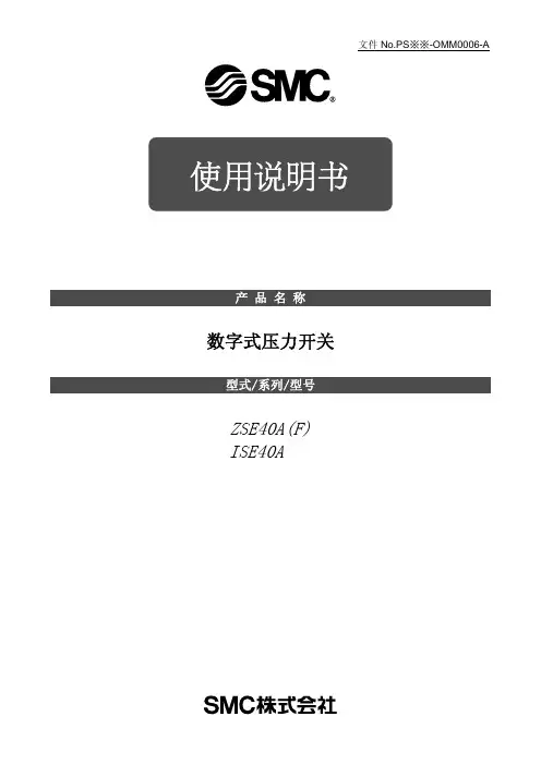
文件No.PS※※-OMM0006-A 使用说明书产 品 名 称数字式压力开关型式/系列/型号ZSE40A(F)ISE40A目录安全注意事项 2 型式表示・型号体系 9 产品各部品名称及功能 11 用语的定义及用语集 12 安装・设置 15 设置方法 15 配管方法 17 配线方法 19 压力设定 21 什么是设定模式 21 功能设定 23 什么是功能选择模式 23 出厂设定 23 F0 单位切换功能 25 F1 OUT1的设定 26 F2 OUT2的设定 29 F3 响应时间的设定 31 F4 自动预设功能的设定 32 F5 模拟输出/自动移位输入的设定 34 F6 显示值微调整的设定 36 F11 分辨率的设定 37 F80 省电模式的设定 38 F81密码输入的设定 39 特殊功能的设定 40 F90 全功能的设定 40 F97 复制功能的选择 42 F98 输出确认 44 F99 恢复出厂设置 46 其他设定 47 维护 50 忘记密码的情况 51 故障的消除 52 规格 59 规格表 59 外形尺寸图 61安全注意事项这里所示的注意事项是为了能安全正确的使用本产品,预先防止对您和他人造成危害或损失。
为了表示这些事项的危险程度,将注意事项分成「注意」「警告」和「危险」三个等级。
请您也遵守和安全相关的其他重要内容,如国际规格(ISO/IEC)、日本工业规格(JIS)※1以及其他安全法规※2。
*1) ISO 4414: Pneumatic fluid power -- General rules relating to systemsISO 4413: Hydraulic fluid power -- General rules relating to systemsIEC 60204-1: Safety of machinery -- Electrical equipment of machines (Part 1: General requirements) ISO 10218-1: Robots for industrial environments—Safety requirements –Part 1: RobotJIS B 8370: 空气压系统通则JIS B 8361: 油压系统通则JIS B 9960-1: 机械类的安全性-机械的电气装置(第1部:一般要求事项)JIS B 8433-1: 工业机器人- 安全要求事项-第1部: 机器人等*2) 劳动安全卫生法 等注意: 错误操作时,人和设备可能受到损伤的事项。
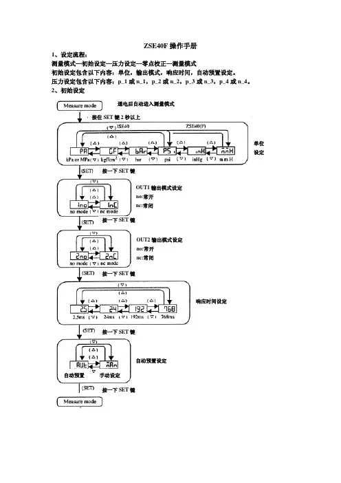
ZSE40F操作手册1、设定流程:测量模式—初始设定—压力设定—零点校正—测量模式初始设定包含以下内容:单位,输出模式,响应时间,自动预置设定。
压力设定包含以下内容:p_1或n_1,p_2或n_2,p_3或n_3,p_4或n_4。
2、初始设定单位设定OUT1输出模式设定no:常开nc:常闭响应时间设定自动预置设定OUT2输出模式设定no:常开nc:常闭自动预置手动设定按住SET键2秒以上通电后自动进入测量模式按一下SET键按一下SET键按一下SET键按一下SET键按一下SET键3、压力设定4、零点校正和其他 (1)按键锁此功能可在设定完成后将按键锁定,防止误操作。
操作方法:测量模式下,按住键5秒钟以上,直至屏幕显示当前按键锁定状态“LoC ”-锁定或“UnL ”-解锁;按或选择是否锁定按键,按键完成设定。
(2)峰值/谷值显示此功能可以显示压力开关从通电时起至当前时刻这段时间内压力开关检测到的最大压力和最小压力值。
峰值显示:按住键1秒钟以上,屏幕开始持续交替显示峰值压力和“Hi ”; 再按住键1秒钟以上,压力开关返回测量模式。
谷值显示:按住键1秒钟以上,屏幕开始持续交替显示谷值压力和“Lo ”; 再按住键1秒钟以上,压力开关返回测量模式。
(3)零点校正当产品通电且不施加气压时,如果显示值不为零,和键同时按住1s 以上,显示值归零。
(压力显示值在传感器±10%F.S.内可进行零点校正。
)手动设定 自动预置设定交替 显示修正值系统重复作动几次,传感器自动记录最佳值改变系统工作状态交替 显示交替 显示交替 显示交替 显示系统重复作动几次,传感器自动记录最佳值输出1输出2仅。
SMC压力开关如何调试?发表于:2019年07月30日17:02转发0针对我司客户对SMC压力开关的调试问题,我们做出了以下总结:问题一、客户:ZSE40F设置1no,2no时,当P1:-7.9,P2:-10.8,P3:-93.8,P4:-100时,信号灯输出混乱,请教是设置原因或产品质量问题?欧迅自动化设备回答:1:对于ZSE40F来说,当设置1no,2no时,在压力输出范围内红绿输出信号灯要亮. 2:压力值输出数值设置一般要求:P1﹤P2﹤P3﹤P4。
压力在P1至P2范围内绿灯亮,压力在P3至P4范围内红灯亮,相应的信号灯在范围外不亮。
3:你的开关应设置成P1:-100,P2:-93.8,P3:-10.8,P4:-7.9,相应设置1no,2no,若真空值为-95.0Kpa(P1:-100~P2:-93.8之间)左右时绿灯亮,这时红灯不会亮,若真空值为-9.0Kpa(P1:-10.8~P2:-7.9之间)左右时红灯亮,这时绿灯不会亮,若压力值在这两者各自的范围外,则信号灯输出恰恰相反。
4:你的压力值要这样设置,建议你使用真空压ZSE40(范围-101.3~10)更合适.问题二、客户:请教当ZSE40F设置成1nc,2nc时,是否信号灯就不亮?欧迅自动化设备简单的回答:设置1nc,2nc仅仅表示在设置范围内的输出灯不亮,在范围外的灯照样亮.问题三、客户:请教ZSE40的信号灯设置怎么与ZSE40F不一样,应如何设置?欧迅自动化设备简单的回答:1.压力开关ZSE40F,ISE40相对应的1no,2no为常开,1nc,2nc为常闭;压力开关ZSE40(真空压)相对应的1no,2no为常闭,1nc,2nc为常开。
2:当设置成1nc,2nc时出现的为n1,n2,n3,n4,这时要求n1﹤n2﹤n3﹤n4,这时压力值在相对应的范围内会亮。
3:ZSE40(真空压)在n1和n4临界点的输出信号也不一样。
附一:SMC压力开关的使用一:使用环境1:适合流体:空气、非腐蚀性气体;2:使用温度:保存时0~50℃,工作时10~50℃。
smczse40A-01-R说明书
1、设置控制压力的方法
(1)短按(ON/OFF)运行键,关闭运行指示灯,压力控制系统关闭。
(2)设置控制上限/下限。
短按SET键1次,进入下限设置状态(对应下限指示灯亮),通过(▲)(▼)设置数值,设置下限完成后,短按SET键进入上限设置,设置方法同上。
(3)设置完成后,按SET键将设定值自动存入电脑芯片(参数修改后,5秒钟内无按键操作会自动保存当前参数设置)。
2、按键定义说明
1.(ON/OFF)运行键:系统运行键,进行参数设置必须关闭运行键,否则设置无法进行。
2.(SET)设置键:短按此按键进入压力上下限设置状态,长按3秒进入系统设置状态。
3.增加键(▲):按键一次数字增加0.01MP,长按2秒后数字增加0.1MPa。
4.减小键(▼):按键一次数字减小0.01MP,长按2秒后数字减小0.1MPa。
SMC压力开关如何调试?发表于:2019 年07 月30日17:02 转发0针对我司客户对SMC压力开关的调试问题,我们做出了以下总结:问题一、客户:ZSE40F设置1no,2no 时,当P1:-7.9,P2:-10.8,P3:-93.8,P4:-100 时,信号灯输出混乱,请教是设置原因或产品质量问题?欧迅自动化设备回答:1:对于ZSE40F来说,当设置1no,2no时,在压力输出范围内红绿输出信号灯要亮• 2:压力值输出数值设置一般要求:P1 < P2< P3< P4。
压力在P1至P2范围内绿灯亮,压力在P3至P4范围内红灯亮,相应的信号灯在范围外不亮。
3:你的开关应设置成P1:-100,P2:-93.8,P3:-10.8,P4:-7.9, 相应设置1no, 2no,若真空值为-95.0Kpa(P1:-100〜P2:-93.8之间)左右时绿灯亮,这时红灯不会亮,若真空值为- 9.0Kpa(P1:-10.8〜P2:-7.9之间)左右时红灯亮,这时绿灯不会亮,若压力值在这两者各自的范围外,则信号灯输出恰恰相反。
4:你的压力值要这样设置,建议你使用真空压ZSE40(范围-101.3〜10)更合适.问题二、客户:请教当ZSE40F设置成1nc, 2nc时,是否信号灯就不亮?欧迅自动化设备简单的回答:设置1nc,2nc 仅仅表示在设置范围内的输出灯不亮,在范围外的灯照样亮.问题三、客户:请教ZSE40的信号灯设置怎么与ZSE4OF不一样,应如何设置?欧迅自动化设备简单的回答:1.压力开关ZSE40F,ISE40相对应的1no,2no为常开,1 nc,2nc 为常闭;压力开关ZSE40滇空压)相对应的1no,2no 为常闭,1nc,2nc 为常开。
2:当设置成1nc,2nc 时出现的为n1,n2,n3,n4,这时要求n1< n2< n3< n4,这时压力值在相对应的范围内会亮。