DM6467 Getting Started Guide
- 格式:pdf
- 大小:67.05 KB
- 文档页数:4

达芬奇 DM6467 评估板 系统软件平台构 建 方 法Revision Table Date Rev. Author Content of revision 1.0 2009-09-01 Andy,LIU OriginalApproval1 系统介绍.......................................................................................................................................4 2 开发环境的建立...........................................................................................................................4 3 网络文件系统的建立...................................................................................................................5 4 tftp 服务的建立 .............................................................................................................................5 5 UBOOT 的使用.............................................................................................................................6 6 启动方式说明...............................................................................................................................8 7 硬盘的恢复...................................................................................................................................9 8 uboot 和 kernel 的编译..................................................................................................................9 9 在 nand flash 上使用 uboot 烧写 kernel .....................................................................................101 系统介绍建立 DM6467 开发平台是进行软件研发的基础,DM6467 EVM 以 LINUX 为 操作系统,文件系统可以放置在 FLASH 中,也可以放置在硬盘中,可以根据具 体的应用进行选取。


之士官方 DM6467 参考资料— 原厂DM6467 开发板 入门指南(英文影印版)本手册详细介绍了DM6467开发板的软件、硬件情况,详细阅读本手册您将可以了解到:硬件如何驳接、DM6467 EVM的设置、怎样连接到一个控制台、怎样运行一个演示软件、怎样启动独立演示程序、如何启动编码+解码演示程序、如何运行网络演示程序、如何安装Linux 、自己编译内核等。
在您使用本手册的过程中有任何技术问题或需要帮助,请联系技术支持:support@ 之士DM6467优惠促销中,请联系销售: sales@更多信息请访问DM6467专题网站:IMPORTANT NOTICETexas Instruments Incorporated and its subsidiaries (TI) reserve the right to make corrections, modifications, enhancements, improvements, and other changes to its products and services at any time and to discontinue any product or service without notice. Customers should obtain the latest relevant information before placing orders and should verify that such information is current and complete. All products are sold subject to TI's terms and conditions of sale supplied at the time of order acknowledgment.TI warrants performance of its hardware products to the specifications applicable at the time of sale in accordance with TI's standard warranty. Testing and other quality control techniques are used to the extent TI deems necessary to support this warranty. Except where mandated by government requirements, testing of all parameters of each product is not necessarily performed.TI assumes no liability for applications assistance or customer product design. Customers are responsible for their products and applications using TI components. To minimize the risks associated with customer products and applications, customers should provide adequate design and operating safeguards.TI does not warrant or represent that any license, either express or implied, is granted under any TI patent right, copyright, mask work right, or other TI intellectual property right relating to any combination, machine, or process in which TI products or services are used. Information published by TI regarding third-party products or services does not constitute a license from TI to use such products or services or a warranty or endorsement thereof. Use of such information may require a license from a third party under the patents or other intellectual property of the third party, or a license from TI under the patents or other intellectual property of TI.Reproduction of information in TI data books or data sheets is permissible only if reproduction is without alteration and is accompanied by all associated warranties, conditions, limitations, and notices. Reproduction of this infor-mation with alteration is an unfair and deceptive business practice. TI is not responsible or liable for such altered documentation.Resale of TI products or services with statements different from or beyond the parameters stated by TI for that product or service voids all express and any implied warranties for the associated TI product or service and is an unfair and deceptive business practice. TI is not responsible or liable for any such statements.Following are URLs where you can obtain information on other Texas Instruments products and application solu-tions:Products ApplicationsAmplifiers Audio /audioData Converters Automotive /automotiveDSP Broadband /broadband Interface Digital Control /digitalcontrol Logic Military /militaryPower Mgmt Optical Networking /opticalnetwork Microcontrollers Security /securityLow Power Wireless /lpw Telephony /telephonyVideo & Imaging /videoWireless /wireless Mailing Address:Texas InstrumentsPost Office Box 655303 Dallas, Texas 75265Copyright © 2008, Texas Instruments IncorporatedEVALUATION BOARD/KIT IMPORTANT NOTICETexas Instruments (TI) provides the enclosed product(s) under the following conditions:This evaluation board/kit is intended for use for ENGINEERING DEVELOPMENT, DEMON-STRATION, OR EVALUATION PURPOSES ONLY and is not considered by TI to be a finished end-product fit for general consumer use. Persons handling the product(s) must have electronics training and observe good engineering practice standards. As such, the goods being provided are not intended to be complete in terms of required design-, marketing-, and/or manufacturing-related protective considerations, including product safety and environmental measures typically found in end products that incorporate such semiconductor components or circuit boards. This evaluation board/kit does not fall within the scope of the European Union directives regarding electromagnetic compatibility, restricted substances (RoHS), recycling (WEEE), FCC, CE or UL, and therefore may not meet the technical requirements of these directives or other related directives.Should this evaluation board/kit not meet the specifications indicated in the User's Guide, the board/kit may be returned within 30 days from the date of delivery for a full refund. THE FORE-GOING WARRANTY IS THE EXCLUSIVE WARRANTY MADE BY SELLER TO BUYER AND IS IN LIEU OF ALL OTHER WARRANTIES, EXPRESSED, IMPLIED, OR STATUTORY, IN-CLUDING ANY WARRANTY OF MERCHANTABILITY OR FITNESS FOR ANY PARTICULAR PURPOSE.The user assumes all responsibility and liability for proper and safe handling of the goods. Further, the user indemnifies TI from all claims arising from the handling or use of the goods. Due to the open construction of the product, it is the user's responsibility to take any and all appropriate precautions with regard to electrostatic discharge.EXCEPT TO THE EXTENT OF THE INDEMNITY SET FORTH ABOVE, NEITHER PARTY SHALL BE LIABLE TO THE OTHER FOR ANY INDIRECT, SPECIAL, INCIDENTAL, OR CON-SEQUENTIAL DAMAGES.TI currently deals with a variety of customers for products, and therefore our arrangement with the user is not exclusive.TI assumes no liability for applications assistance, customer product design, software performance, or infringement of patents or services described herein.Please read the User's Guide and, specifically, the Warnings and Restrictions notice in the User's Guide prior to handling the product. This notice contains important safety information about temperatures and voltages. For additional information on TI's environmental and/or safety pro-grams, please contact the TI application engineer or visit /esh.No license is granted under any patent right or other intellectual property right of TI covering or relating to any machine, process, or combination in which such TI products or services might be or are used.Mailing Address:Texas InstrumentsPost Office Box 655303Dallas, Texas 75265Copyright © 2008, Texas Instruments IncorporatedFCC WarningThis evaluation board/kit is intended for use for ENGINEERING DEVELOPMENT, DEMON-STRATION, OR EVALUATION PURPOSES ONLY and is not considered by TI to be a finished end-product fit for general consumer use. It generates, uses, and can radiate radio frequency energy and has not been tested for compliance with the limits of computing devices pursuant to part 15 of FCC rules, which are designed to provide reasonable protection against radio frequency interference. Operation of this equipment in other environments may cause interfer-ence with radio communications, in which case the user at his own expense will be required to take whatever measures may be required to correct this interference.PrefaceAbout This GuideThe DVEVM (Digital Video Evaluation Module) kit is an evaluationplatform that showcases the DM646x architecture and lets usersevaluate the power and performance of the DM646x as a multimediaengine.This guide gives you overview information about the board and thesoftware provided with the board. It is intended to be used as anintroductory document for the DVEVM. Other documents provide morein-depth information. See the DVEVM release notes for a complete list ofdocuments that have been included with the product.Additional Documents and ResourcesYou can use the following sources to supplement this user’s guide:❏Spectrum Digital website:/boards/evmdm6467❏TI Linux Community for DaVinci Processors:❏TI DaVinci Software Updates: /dvevmupdates❏TI DaVinci Technology Developers Wiki: ❏Codec Engine Application Developer's Guide (SPRUE67)❏Other PDF documents included with the DVEVM kit❏Section 4.11 lists documentation in the DVSDK software installation.❏SoC Analyzer Help menuvNotational ConventionsNotational ConventionsThis document uses the following conventions:❏Program listings, program examples, and interactive displays areshown in a mono-spaced font. Examples use bold for emphasis,and interactive displays use bold to distinguish commands that youenter from items that the system displays (such as prompts,command output, error messages, etc.).❏Square brackets ( [ and ] ) identify an optional parameter. If you usean optional parameter, you specify the information within thebrackets. Unless the square brackets are in a bold typeface, do notenter the brackets themselves.TrademarksThe Texas Instruments logo and Texas Array Instruments are registered trademarks of TexasInstruments. Trademarks of Texas Instrumentsinclude: TI, DaVinci, the DaVinci logo, XDS, CodeComposer, Code Composer Studio, Probe Point,Code Explorer, DSP/BIOS, RTDX, Online DSPLab, DaVinci, TMS320, TMS320C54x,TMS320C55x, TMS320C62x, TMS320C64x,TMS320C67x, TMS320C5000, andTMS320C6000.MS-DOS, Windows, and Windows NT are trademarks of MicrosoftCorporation.UNIX is a registered trademark of The Open Group in the United Statesand other countries.Linux is a registered trademark of Linus Torvalds.Solaris, SunOS, and Java are trademarks or registered trademarks ofSun Microsystems, Inc.All other brand, product names, and service names are trademarks orregistered trademarks of their respective companies or organizations.December 18, 2008viContents 1DVEVM Overview . . . . . . . . . . . . . . . . . . . . . . . . . . . . . . . . . . . . . . . . . . . . . . . . . . . . . . . . . . .1-1 This chapter introduces the DVEVM (Digital Video Evaluation Module) kit.1.1Welcome! . . . . . . . . . . . . . . . . . . . . . . . . . . . . . . . . . . . . . . . . . . . . . . . . . . . . . . . . . . . .1-21.2What’s in this Kit?. . . . . . . . . . . . . . . . . . . . . . . . . . . . . . . . . . . . . . . . . . . . . . . . . . . . . .1-21.3What’s on the Board?. . . . . . . . . . . . . . . . . . . . . . . . . . . . . . . . . . . . . . . . . . . . . . . . . . .1-31.4What’s Next? . . . . . . . . . . . . . . . . . . . . . . . . . . . . . . . . . . . . . . . . . . . . . . . . . . . . . . . . .1-4 2EVM Hardware Setup . . . . . . . . . . . . . . . . . . . . . . . . . . . . . . . . . . . . . . . . . . . . . . . . . . . . . . .2-1 This chapter tells you how to set up the EVM hardware.2.1Setting Up the Hardware . . . . . . . . . . . . . . . . . . . . . . . . . . . . . . . . . . . . . . . . . . . . . . . .2-22.2Connecting to a Console Window . . . . . . . . . . . . . . . . . . . . . . . . . . . . . . . . . . . . . . . . .2-7 3Running the Demonstration Software . . . . . . . . . . . . . . . . . . . . . . . . . . . . . . . . . . . . . . . . . .3-1 This chapter explains how to run the software demos provided with the DVEVM kit.3.1Default Boot Configuration. . . . . . . . . . . . . . . . . . . . . . . . . . . . . . . . . . . . . . . . . . . . . . .3-23.2Starting the Standalone Demos . . . . . . . . . . . . . . . . . . . . . . . . . . . . . . . . . . . . . . . . . . .3-23.3Running the Standalone Demos. . . . . . . . . . . . . . . . . . . . . . . . . . . . . . . . . . . . . . . . . . .3-43.3.1Shutting Down the Demos . . . . . . . . . . . . . . . . . . . . . . . . . . . . . . . . . . . . . . .3-53.3.2About the Encode + Decode Demo . . . . . . . . . . . . . . . . . . . . . . . . . . . . . . . .3-63.3.3About the Encode Demo . . . . . . . . . . . . . . . . . . . . . . . . . . . . . . . . . . . . . . . .3-73.3.4About the Decode Demo . . . . . . . . . . . . . . . . . . . . . . . . . . . . . . . . . . . . . . . .3-93.3.5About the Third Party Menu. . . . . . . . . . . . . . . . . . . . . . . . . . . . . . . . . . . . .3-103.4Running the Demos from the Command Line . . . . . . . . . . . . . . . . . . . . . . . . . . . . . . .3-103.5Running the Network Demo. . . . . . . . . . . . . . . . . . . . . . . . . . . . . . . . . . . . . . . . . . . . .3-12 4DVEVM Software Setup . . . . . . . . . . . . . . . . . . . . . . . . . . . . . . . . . . . . . . . . . . . . . . . . . . . . .4-1 This chapter explains how to use the software provided with the DVEVM kit.4.1Software Overview. . . . . . . . . . . . . . . . . . . . . . . . . . . . . . . . . . . . . . . . . . . . . . . . . . . . .4-24.1.1Command Prompts in This Guide . . . . . . . . . . . . . . . . . . . . . . . . . . . . . . . . .4-34.1.2Software Components . . . . . . . . . . . . . . . . . . . . . . . . . . . . . . . . . . . . . . . . . .4-44.2Preparing to Install . . . . . . . . . . . . . . . . . . . . . . . . . . . . . . . . . . . . . . . . . . . . . . . . . . . . .4-54.3Installing the Software . . . . . . . . . . . . . . . . . . . . . . . . . . . . . . . . . . . . . . . . . . . . . . . . . .4-54.3.1Installing the Target Linux Software. . . . . . . . . . . . . . . . . . . . . . . . . . . . . . . .4-64.3.2Installing the DVSDK Software. . . . . . . . . . . . . . . . . . . . . . . . . . . . . . . . . . . .4-74.3.3Installing the A/V Demo Files. . . . . . . . . . . . . . . . . . . . . . . . . . . . . . . . . . . . .4-84.3.4Installing the SoC Analyzer . . . . . . . . . . . . . . . . . . . . . . . . . . . . . . . . . . . . . .4-9viiContentsviii4.3.5Exporting a Shared File System for Target Access . . . . . . . . . . . . . . . . . . . 4-94.3.6Testing the Shared File System . . . . . . . . . . . . . . . . . . . . . . . . . . . . . . . . . 4-114.3.7Notes on Using Evaluation/Production Codecs . . . . . . . . . . . . . . . . . . . . . 4-12 4.4Setting Up the Build/Development Environment. . . . . . . . . . . . . . . . . . . . . . . . . . . . . 4-124.4.1Writing a Simple Program and Running it on the EVM. . . . . . . . . . . . . . . . 4-13 4.5Building a New Linux Kernel. . . . . . . . . . . . . . . . . . . . . . . . . . . . . . . . . . . . . . . . . . . . 4-13 4.6Rebuilding the DVEVM Software for the Target . . . . . . . . . . . . . . . . . . . . . . . . . . . . . 4-15 4.7Booting the New Linux Kernel. . . . . . . . . . . . . . . . . . . . . . . . . . . . . . . . . . . . . . . . . . . 4-16 4.8Testing the Build Environment . . . . . . . . . . . . . . . . . . . . . . . . . . . . . . . . . . . . . . . . . . 4-17 4.9Using the Digital Video Test Bench (DVTB) . . . . . . . . . . . . . . . . . . . . . . . . . . . . . . . . 4-18 4.10Running The SoC Analyzer. . . . . . . . . . . . . . . . . . . . . . . . . . . . . . . . . . . . . . . . . . . . . 4-19 4.11Documentation for DSP-Side Development . . . . . . . . . . . . . . . . . . . . . . . . . . . . . . . . 4-20A Additional Procedures . . . . . . . . . . . . . . . . . . . . . . . . . . . . . . . . . . . . . . . . . . . . . . . . . . . . . .A-1This appendix describes optional procedures you may use depending on your setup and specific needs.A.1Putting Demo Applications in the Third-Party Menu. . . . . . . . . . . . . . . . . . . . . . . . . . . . . . . . . . . A-2A.2Setting Up a TFTP Server . . . . . . . . . . . . . . . . . . . . . . . . . . . . . . . . . . . . . . . . . . . . . . . . . . . . . . A-4A.3Alternate Boot Methods . . . . . . . . . . . . . . . . . . . . . . . . . . . . . . . . . . . . . . . . . . . . . . . . . . . . . . . . A-5A.4Updating and Restoring the Bootloaders. . . . . . . . . . . . . . . . . . . . . . . . . . . . . . . . . . . . . . . . . . . A-7A.5Installing uImage in NAND Flash. . . . . . . . . . . . . . . . . . . . . . . . . . . . . . . . . . . . . . . . . . . . . . . . . A-9A.6Rebuilding DSP/BIOS Link. . . . . . . . . . . . . . . . . . . . . . . . . . . . . . . . . . . . . . . . . . . . . . . . . . . . . A-10A.7Restoring and Updating the EVM Hard Disk Drive. . . . . . . . . . . . . . . . . . . . . . . . . . . . . . . . . . . A-11DVEVM Overview This chapter introduces the DVEVM (Digital Video Evaluation Module) kit.Topic Page 1.1Welcome! . . . . . . . . . . . . . . . . . . . . . . . . . . . . . . . . . . . . . . . . . . . . . . . 1–2 1.2What’s in this Kit?. . . . . . . . . . . . . . . . . . . . . . . . . . . . . . . . . . . . . . . . 1–2 1.3What’s on the Board?. . . . . . . . . . . . . . . . . . . . . . . . . . . . . . . . . . . . . 1–3 1.4What’s Next? . . . . . . . . . . . . . . . . . . . . . . . . . . . . . . . . . . . . . . . . . . . . 1–41-1Welcome!1-21.1Welcome!Your new DVEVM (Digital Video EvaluationModule) kit will allow you to evaluate TI’s newDaVinci TM Technology and the DM646xarchitecture.This technology brings together system-solutioncomponents tailored for efficient and compellingdigital video and audio.1.2What’s in this Kit?Your DVEVM kit contains the following hardware items. Section 2.1,Setting Up the Hardware tells how to connect these components.❏EVM Board . This board contains a DaVinci TMS320DM6467 dual-core device with an ARM9 and C64+ DSP for development ofapplications that use both a general-purpose processor and an accelerated DSP processor.❏Hard Disk Drive . The hard drive provided with the EVM is a 2.5"Spinpoint drive with 40 GB of storage. The drive speed in 5400 RPM and it has an 8MB cache. The drive is an Ultra ATA 66/100/133 IDE.Software has been preloaded on this EVM board’s hard disk drive.❏IR Remote Control . This universal remote control is included to provide a user interface to the demo applications.❏Cables. Cables used to connect the EVM board to peripheral devices and to a host Linux workstation used for development are provided in the kit.The DVEVM kit also comes with the following software. Information about how to use the software components is provided in Chapter 4.❏DaVinci Digital Video Evaluation Kit.❏TI DaVinci Demonstration Version of MontaVista Linux Pro v5.0Target ❏TI DaVinci Demonstration Version of MontaVista Linux Pro v5.0Tools ❏A/V Media Clips ❏Spectrum Digital EVM Tools ❏SoC AnalyzerWhat’s on the Board?1.3What’s on the Board?The EVM comes loaded with peripherals your multimedia applicationsmay need to make use of. The hard drive on the board also comes pre-loaded with demonstration software. The following block diagram showsthe major hardware components.Figure 1–1 EVM Hardware Block DiagramFor more information about the EVM hardware, see the DaVinci EVMwebsite at /boards/evmdm6467.DVEVM Overview1-3What’s Next?1-41.4What’s Next?To get started evaluating the DVEVM kit and developing applications for the DM646x, begin by using this Getting Started guide. It will step you through connecting the hardware, testing the software, and beginning to develop applications.When you are ready for more information about DaVinci Technology and the DM646x architecture, see the following:❏Spectrum Digital website:/boards/evmdm6467❏TI Linux Community for DaVinci Processors: ❏TI DaVinci Software Updates: /dvevmupdates ❏TI DaVinci Technology Developers Wiki: ❏Codec Engine Application Developer's Guide (SPRUE67)❏Other PDF documents included with the DVEVM kit❏Section 4.11 lists documentation in the DVSDK software installation.❏SoC Analyzer Help menuEVM Hardware SetupThis chapter tells you how to set up the EVM hardware.Topic Page 2.1Setting Up the Hardware. . . . . . . . . . . . . . . . . . . . . . . . . . . . . . . . . . . 2–2 2.2Connecting to a Console Window . . . . . . . . . . . . . . . . . . . . . . . . . . . 2–72-1Setting Up the Hardware2-22.1Setting Up the HardwareTo set up the hardware provided with the EVM, use the steps in the sections that follow. You may skip sections if you do not need to access a particular peripheral. For example, if you do not need to use the serial cable, skip that section.1)The EVM is sensitive to static discharges. Usea grounding strap or other device to prevent damaging the board.Be sure to connect communication cables before applying power to any equipment.2)Verify that the EVM board’s EMU0/1 select switch (S1) is setcorrectly. The settings shown here enable both ARM and DSP JTAGfor emulation debugging.Setting Up the HardwareEVM Hardware Setup 2-33)Verify that the EVM board’s SW3 boot/muxing configuration switch iscorrectly set. The BM1, BM2, and BM3 switches should be set to On.These switch settings, which are shown in the following figure,enable the following:■SPI boot mode■EMIF A is 8-bit data bus for CS2■PCI pin multiplexing enabled on DM6467■DSP is booted via ARM processor4)Connect the Ethernet cable to the Ethernet port on the EVM boardand to an Ethernet network port. Note that the U-Boot bootargs mustinclude "ip=dhcp" to enable the network connection.Setting Up the Hardware2-45)Connect a video source (for example, a camera or DVD player) to thecomponent input video connectors (J1, J2, J3). Note: To run the demos described in Chapter 3, you will need to have an HD (720p) video source connected to the EVM board's component input connectors.6)Connect your video display to the EVM board’s component outputvideo connectors (J10, J11 and J12) using the component cables included with the DVEVM kit. Note: To run the demos described in Chapter 3, you will need to have an HD display connected to the EVMboard's component output connectors.Setting Up the HardwareEVM Hardware Setup 2-57)Connect an audio speaker to the headphone connector (P4).8)Connect an audio source to the microphone connector (P8).Setting Up the Hardware2-69)If you plan to use the UART port for a console window, connect theRS-232 null modem cable to the EVM UART port (P1) and to the COM port of your host workstation.10)Power on your video input and output devices.11)Connect the power cable to the EVM power jack on the board. To beESD safe, plug in the other end of the power cable only after you have connected the power cord to the board. Then turn on the board.12)The initial screen of the demo software should be displayed on yourvideo output device. Use the IR remote to run the software asdescribed in Chapter 3.Connecting to a Console Window 2.2Connecting to a Console WindowYou can open a console window that allows you to watch and interruptEVM boot messages by following these steps:1)Connect a serial cable between the serial port on the EVM and theserial port (for example, COM1) on a PC.2)Run a terminal session (such as Minicom on Linux or HyperTerminalon Windows) on the workstation and configure it to connect to thatserial port with the following characteristics:■Bits per Second: 115200■Data Bits: 8■Parity: None■Stop Bits: 1■Flow Control: None3)When you power on the EVM, you will see boot sequence messages.You can press a key to interrupt the boot sequence and typecommands in the U-Boot command shell. In this guide, commands tobe typed in the U-Boot shell are indicated by anEVM # prompt.EVM Hardware Setup2-72-8Running the Demonstration Software This chapter explains how to run the software demos provided with theDVEVM kit.Topic Page3.1Default Boot Configuration. . . . . . . . . . . . . . . . . . . . . . . . . . . . . . . . . 3–23.2Starting the Standalone Demos. . . . . . . . . . . . . . . . . . . . . . . . . . . . . 3–23.3Running the Standalone Demos . . . . . . . . . . . . . . . . . . . . . . . . . . . . 3–43.4Running the Demos from the Command Line . . . . . . . . . . . . . . . . 3–103.5Running the Network Demo . . . . . . . . . . . . . . . . . . . . . . . . . . . . . . . 3–123-1Default Boot Configuration 3-23.1Default Boot ConfigurationOut of the box, the EVM boots from flash and starts the demos automatically after a few seconds when you power up the board. It does not require an NFS mount or a TFTP server to run the standard demos. Note: The default U-Boot bootargs definition sets "ip=off", which disables the Ethernet connection.The out-of-the-box boot parameters are listed in Section A.3.1. The following are alternate ways you may want to boot the board:❏TFTP boot with hard drive file system (Section A.3.2)❏Flash boot with NFS file system (Section A.3.3)❏TFTP boot with NFS file system (Section A.3.4)To abort the standard boot, press any key in the console window (see Section 2.2). Also see Section A.3, Alternate Boot Methods if you want to change the boot configuration.3.2Starting the Standalone DemosWhen you connect the EVM hardware, the pre-loaded examples run automatically on the display connected to the EVM board's component output connectors, using a 720p (HD) video source connected to the component input connectors. These examples encode and decode audio, video, and speech. There are two ways to use the demos:❏Standalone. This is the default power-on mode. The demos run automatically with no connection to a workstation in the default bootconfiguration. This is the mode documented in the rest of this chapter.The standalone demo was set up by the DVSDK, which copies the file /examples/dvevmdemo to the directory /etc/rc.d/init.d (the central repository for startup scripts). This file is symbolically linked to /etc/rc.d/rc3id/S88demo. When the board boots up and enters runlevel 3, this file is executed to start the demo web server and the demo interface.❏Command line. Once you have connected the EVM to a workstation and installed the necessary software (as described in Section 4.3.1,Installing the Target Linux Software ), you can run the demos from the board’s Linux command line. For further information on running the demos from the command line, see the demo documentation that is linked to by the DVSDK release notes.Note: When you run the demos from the command line, make sure the interface process used by the standalone mode demos is notStarting the Standalone DemosRunning the Demonstration Software 3-3running. Otherwise you will see error messages raised when device drivers fail to open.Once the EVM board has booted, the displayshould show a picture of the remote control.You use the IR remote to control the demos.The order of the buttons on the actual remotemay be different from the picture; if yourremote looks different, find the buttons withthe same labels on your remote.To use the demos in standalone mode, followthese steps:1)Check to make sure the batteries areinstalled in your IR remote.2)Make sure an HD (720p) video source isconnected to the EVM board'scomponent input connectors. Also makesure an HD display is connected to theEVM board's component outputconnectors.Note: The demos do not currentlysupport composite video output.3)The initial screen shows a diagram of theIR remote, which you use to run thestandalone demos. Take a minute to lookat the functions of the various buttons.4)Since this is a universal remote, you mayneed to set it to use the codes necessaryto run the DVEVM demos. To do this, holddown the "Code Search" button until thered light on the remote stays lit. Thenpress the "DVD" button and enter "0020"as the code.5)If you accidentally put the remote in TV or some other mode, press"DVD" to return the remote to the correct mode.6)If the remote does not accept the DVD+0020 code, do a full reset byremoving the batteries, pressing the Power button for at least a minute, then reinserting the batteries. Then program the remote as in Step 3.。

Dell™ PowerConnect™M6348 Stackable SwitchesGetting Started Guide使用入门指南入門指南Guide de mise en routeHandbuch zum EinstiegPanduan Pengaktifanはじめに시작 안내서Guía de introducciónהדובע תליחת ךירדמModel PCM6348w w w.d e l l.c o m|s u p p o r t.d e l l.c o mDell™ PowerConnect™M6348 Stackable SwitchGetting Started GuideModel PCM6348w w w.d e l l.c o m|s u p p o r t.d e l l.c o mNotes, Notices, and CautionsNOTE: A NOTE indicates important information that helps you make better use of your computer.NOTICE: A NOTICE indicates either potential damage to hardware or loss of data and tells you how to avoid the problem.CAUTION: A CAUTION indicates a potential for property damage, personal injury, or death.____________________Information in this document is subject to change without notice.©2009Dell Inc.All rights reserved.Reproduction in any manner whatsoever without the written permission of Dell Inc.is strictly forbidden.Trademarks used in this text: Dell, the DELL logo, and PowerConnect are trademarks of Dell Inc.; Microsoft and Windows are registered trademarks of Microsoft Corporation.Other trademarks and trade names may be used in this document to refer to either the entities claiming the marks and names or their products. Dell Inc. disclaims any proprietary interest in trademarks and trade names other than its own.Model PCM6348November 2009P/N H851N Rev. A01ContentsInstallationSite Preparation (5)Unpacking the Switch (5)Package Contents (5)Unpacking Steps (5)Connecting a Switch to a Terminal (6)Assembling a Stack (6)Starting and Configuring the SwitchConnecting the Terminal to the Switch (8)Booting the Switch (9)Initial Configuration (9)Initial Configuration Procedure (10)Example Session (10)Managing a StackMaster and Member Switches (13)Stack Startup (13)Topology Discovery (13)Auto Stack ID Assignment (14)Firmware Version Checking (14)System Initialization (14)CLI/ Telnet/ Web Interface (15)Insertion and Removal of Switches (15)Operating as Standalone Switch (15)Stack ID Renumbering (15)User Controls (15)3Advanced Configuration (16)Retrieving an IP Address From a DHCP Server (16)Security Management and Password Configuration (17)Managing the SwitchUsing a Web Browser to Manage the Switch (20)Starting the Application (20)Understanding the Interface (20)4InstallationThis document provides basic information to install, configure, and operateDell™PowerConnect™ M6348 systems. For more information, see the Hardware Owner’s Manual, which is available on your User Documentation CD, or check the Dell Support web site at for the latest updates on documentation and firmware.Site PreparationBefore installing the switch, make sure that the chosen installation location meets the site requirements specified in the Hardware Owner’s Manual.Unpacking the SwitchPackage ContentsWhen unpacking each switch, make sure that the following items are included:•One PowerConnect switch•One USB type A-to-DB9 serial cable•User Documentation CD•Getting Started Guide•Product Information GuideUnpacking StepsNOTE: Before unpacking the switch, inspect the container and immediately report any evidence ofdamage.1Place the container on a clean, flat surface and cut all straps securing the container.2Open the container or remove the container top.3Carefully remove the switch from the container and place it on a secure and clean surface.4Remove all packing material.5Inspect the product and accessories for damage.Getting Started Guide56Getting Started Guidewww.dell.com|support.dell.co m Connecting a Switch to a Terminal1Connect the DB9 connector of the USB-to-DB9 serial cable to a VT100 terminal or to a computer running VT100 terminal emulation software.2Connect the USB connector at the other end to the USB port on the switch. NOTE: If you are installing a stack of switches , connect the terminal to the Master Switch. When a stack is powered up for the first time, the switches elect the Master Switch, which may occupy any location in the stack. If you connect the terminal to a member (non-Master) switch, you will not be able to use the command line interface (CLI).Assembling a Stack The software supports up to 12 stacked switches, supporting up to 576 1G ports. Each PowerConnect M6348 switch provides two stacking ports at the bottom of the switch. CAUTION: Ensure that a switch is turned off before adding it to the e the 1-meter stacking cables to connect the stacking ports in the following manner: 1Insert a stacking cable in the bottom stacking port on the first switch.2Connect the cable to the upper stacking port on the next switch.3Continue connecting each switch to the next until all switches are connected in a ring.4On the last switch in the stack, connect the cable to the upper stacking port on the first switch to create a loop.If necessary, use a separately purchased 3-meter stacking cable to connect the last switch to the first.Figure 1 shows a chassis with six connected M6348 switches.Getting Started Guide 7Figure 1.Connecting a Stack of SwitchesNOTE: The resulting ring topology allows the entire stack to function as a single switch with resilient fail-over capabilities.stacking cableupper and lowerstacking ports8Getting Started Guide ww w .d e l l .c o m | s u p p o r t .d e l l .c o m Starting and Configuring the Switch After completing all external connections, connect a terminal to a switch to configure the switch or stack. Additional advanced functions are described in the User's Guide located on your User Documentation CD.NOTE: Read the release notes for this product before proceeding. You can download the release notes from the Dell Support website at .NOTE: We recommend that you obtain the most recent version of the user documentation from the DellSupport website at . Connecting the Terminal to the Switch To monitor and configure the switch via serial console, use the console port on the rear of theswitch to connect it to a VT100 terminal or to a computer running VT100 terminal emulation software. The console port is implemented as a data terminal equipment (DTE) connector.The following is required to use the console port:•VT100-compatible terminal or a desktop or a portable system with a serial port, running VT100 terminal emulation software.• A serial cable (provided) with a USB type A connector for the console port and DB9 connector for the terminal.Perform the following tasks to connect a terminal to the switch console port: NOTE: If you are installing a stack of switches , you need to assemble and cable the stack before powering up and configuring it. 1Connect the DB9 connector on the serial cable to the terminal running VT100 terminal emulation software.2Configure the terminal emulation software as follows:a Select the appropriate serial port (serial port 1 or serial port 2) to connect to the console.b Set the data rate to 9600 baud.c Set the data format to 8 data bits, 1 stop bit, and no parity.d Set the flow control to none.e Set the terminal emulation mode to VT100.f Select Terminal keys for Function, Arrow, and Ctrl keys. Make sure that the setting is for Terminal keys (not Microsoft ® Windows ® keys). NOTE: When using HyperTerminal with Microsoft Windows 2000, make sure that you have Windows 2000 Service Pack 2 or later installed. With Windows 2000 Service Pack 2, the arrow keys function properly in HyperTerminal's VT100 emulation. Go to for more information on Windows 2000 service packs.3Connect the USB type A connector on the USB cable directly to the switch USB console port. The PowerConnect M6348 USB console port is located on the left side of the rear panel, asshown in Figure 2.NOTE: If you are installing a stack of switches, connect the terminal to the Master Switch. When a stack is powered up for the first time, the switches elect the Master Switch, which may occupy any location in the stack. If you connect the terminal to a member switch, you will not be able to use the CLI. Figure 2.Connecting to the Console PortBooting the SwitchRefer to the Hardware Owner’s Manual for instructions on booting the switch.Initial ConfigurationNOTE: The initial simple configuration procedure is based on the following assumptions:•The PowerConnect switch was never configured before and is in the same state as when you received it.•The PowerConnect switch booted successfully.•The console connection was established and the Dell Easy Setup Wizard prompt appears on thescreen of a VT100 terminal or terminal equivalent.The initial switch configuration is performed through the console port. After the initialconfiguration, you can manage the switch either from the already-connected console port or remotely through an interface defined during the initial configuration.NOTE: The switch is not configured with a default user name and password.NOTE: All of the settings below are necessary to allow the remote management of the switch through Telnet (Telnet client) or HTTP (Web browser).console portwww.dell.com|support.dell.comBefore setting up the initial configuration of the switch, obtain the following information from your network administrator:•The IP address to be assigned to the management VLAN.•The IP subnet mask for the network.•The IP address of the management VLAN default gateway.Initial Configuration Procedure Y ou can perform the initial configuration using the Dell Easy Setup Wizard, or by using the Command Line Interface (CLI). The Setup Wizard automatically starts when the switch configuration file is empty. Y ou can exit the wizard at any point by entering [ctrl+z], but all configuration settings specified will be discarded (the switch will use the default values).For more information on CLI initial configuration see the User Guide . This Getting Started Guide shows how to use the Setup Wizard for initial switch configuration. The wizard sets up the following configuration on the switch:•Establishes the initial privileged user account with a valid password. The wizard configures one privileged user account during the setup. •Enables CLI login and HTTP access to use the local authentication setting only.•Sets up the IP address for the management VLAN.•Sets up the SNMP community string to be used by the SNMP manager at a given IP address. Y ou may choose to skip this step if SNMP management is not used for this switch. •Allows you to specify the management server IP or permit management access from all IP addresses.•Configures the default gateway IP address.Example Session This section describes an Easy Setup Wizard session. The following values are used by the example session:•The SNMP community string to be used is DellNetworkManager .•The network management system IP address is 192.168.2.1.•The user name is admin , and password is admin123.•The IP address for the management VLAN is 192.168.2.1:255.255.255.0.•The default gateway is 0.0.0.0.The setup wizard configures the initial values as defined above. After you complete the wizard, the switch is configured as follows:•SNMPv1/2c is enabled and the community string is set up as defined above. SNMPv3 is disabled by default.•The admin user account is set up as defined.• A network management system is configured. From this management station, you can access the SNMP, HTTP, and CLI interfaces. Y ou may also choose to allow all IP addresses to access these management interfaces by choosing the (0.0.0.0) IP address.•An IP address is configured for the default management VLAN (1).• A default gateway address is configured.NOTE: In the example below, the possible user options are enclosed in [ ]. Also, where possible, the default value is provided in { }. If you press <Enter> with no options defined, the default value is accepted.Help text is in parentheses.The following example contains the sequence of prompts and responses associated with running an example Dell Easy Setup Wizard session, using the input values listed above.After the switch completes the POST and is booted, the following dialog appears:Unit 1 - Waiting to select management unit)>Applying configuration, please wait ...Welcome to Dell Easy Setup WizardThe Setup Wizard guides you through the initial switch configuration, and gets you up and running as quickly as possible. You can skip the setup wizard, and enter CLI mode to manually configure the switch. You must respond to the next question to run the setup wizard within 60 seconds, otherwise the system will continue with normal operation using the default system configuration.Note: You can exit the setup wizard at any point by entering [ctrl+z].Would you like to run the setup wizard (you must answer this question within 60 seconds)? [Y/N] yStep 1:The system is not setup for SNMP management by default. To manage the switch using SNMP (required for Dell Network Manager) you can . Set up the initial SNMP version 2 account now.. Return later and setup other SNMP accounts. (For more information on setting up an SNMP version 1 or 3 account, see the user documentation).Would you like to setup the SNMP management interface now? [Y/N] nwww.dell.com|support.dell.comStep 2:Now we need to setup your initial privilege (Level 15) user account. This account is used to login to the CLI and Web interface. You may setup other accounts and change privilege levels later. For more information on setting up user accounts and changing privilege levels, see the user documentation.To setup a user account:Please enter the user name. [root]:root Please enter the user password:********Please reenter the user password:********Step 3:Next, an IP address is setup. The IP address is defined on the default VLAN (VLAN #1), of which all ports are members. This is the IP address you use to access the CLI, Web interface, or SNMP interface for the switch. Optionally you may request that the system automatically retrieve an IP address from the network via DHCP (this requires that you have a DHCP server running on the network).To setup an IP address:Please enter the IP address of the device (A.B.C.D) or enter "DHCP" (without the quotes) to automatically request an IP address from the network DHCP server. [192.168.2.1]:192.168.2.1Please enter the IP subnet mask (A.B.C.D or /nn). [255.255.255.0]:255.255.255.0Step 4:Finally, setup the default gateway. Please enter the IP address of the gateway from which this network is reachable. [0.0.0.0]:This is the configuration information that has been collected:User Account setup = root Password = ********Management IP address = 192.168.2.1 255.255.255.0Default Gateway = 0.0.0.0Step 5:Do you want to select the operational mode as Simple Mode? [Y/N] nStep 6:If the information is correct, please select (Y) to save the configuration, and copy to the start-up configuration file. If the information is incorrect, select (N) to discard configuration and restart the wizard: [Y/N] yThank you for using Dell Easy Set up Wizard. You will now enter CLI mode.Managing a StackMaster and Member SwitchesA stack of switches can be managed as a single entity when connected together. The stack can be managed from a web-based interface, an SNMP management station, or a CLI. When a stack is created, one switch automatically becomes the master switch. Y ou can manually allocate an IP address to the master switch using the console, or let DHCP do so automatically. Afterwards,you can manage the entire stack through the IP address of the Master Switch. The Master Switch detects and reconfigures the ports with minimal operational impact in the event of:•Switch failure•Inter-switch stacking link failure•Switch insertion•Switch removalIf the Master Switch goes off line, any of the Member Switches in the stack can replace it.The system will elect a new Master Switch and reconfigure the System Configuration for the stack. Stack StartupTopology DiscoveryWhen a stack is formed, a topology discovery process builds up a database that contains information about all of the switches in the stack, including the Firmware Version, Hardware Version, Management Preference, Switch MAC Address, and Switch Serial Number. Y ou can use the command line interface (CLI) or the Web interface to view this information.NOTE: See the CLI Reference Manual and the User’s Guide for assistance with the CLI and Webinterface, respectively.www.dell.com|support.dell.comAuto Stack ID Assignment During the stack formation process, every switch is assigned a Stack ID. Once Stack ID assignment is complete, each switch saves its Stack ID into the nonvolatile FLASH memory. Y ou can use the CLI or the Web interface to view the stack IDs. Firmware Version Checking Following Stack ID assignment, the Master Switch performs a consistency check to make sure that all switches in the stack are running the same firmware version.If the switch software versions do not match, then the ports on the member switch will not become valid for operation. This condition is known as the Suspended Stacking Mode. Y ou can then synchronize the firmware on the member switch with the firmware that is running on the Master Switch. System Initialization If the Master Switch determines during the firmware version consistency check that all switches are running the same version of firmware, the switch will be initialized for Stacking Mode.System Initialization for Normal Stacking Mode The Master Switch will initialize the stack using the last saved system configuration file. For those switches that do not have a configuration file, the system will apply default settings to those switches.If the configuration file is corrupted, the Master Switch will initialize the stack and set it to the Factory Default Configuration.Y ou can save the configuration file. The Master Switch automatically distributes the configuration file to the member switches. If the Master Switch later becomes unavailable, a Member Switch becomes the new Master Switch and configures the stack with the latest configuration synchronized from the Master Switch.System Initialization for Suspended Stacking Mode After system initialization is complete, the Master Switch will enter Suspended Stacking Mode if the firmware versions of the stack are inconsistent. In this mode, only the Master Switch is initialized with configuration file information. None of the member switches are initialized. This forces all member switches to remain in non-operational mode.NOTE: All ports disabled by default.CLI/ Telnet/ Web InterfaceY ou can use the CLI / WEB / SNMP to synchronize the firmware that is stored in the Master Switch to a member switch.Insertion and Removal of SwitchesY ou can insert and remove switches to/from the current stack without cycling the power. The entire network may be affected when a topology change occurs, as a stack reconfiguration will take place.A new Master Switch will not be re-elected, unless the Master Switch was removed from the stack. Stack reconfiguration takes a maximum of two minutes in a stack of twelve switches, less time for smaller stacks.Operating as Standalone SwitchIf a switch cannot detect a stacking partner on a port enabled for stacking, the switch will operate as a standalone switch. If a stacking partner is detected, the switch will always operate in stacking mode.Stack ID RenumberingY ou can manually assign Stack IDs to a switch. A switch can only be assigned a Stack ID that has not already been assigned to another switch in the stack. Any configuration information that was saved for the new Stack ID is applied to the switch that is taking that Stack ID.User ControlsUse the following CLI commands to control this feature. See the CLI Reference Manual for details on the syntax of each command.movemanagementreloadmemberset descriptionswitch priorityswitch renumberstackingshow stack-portshow stack-port countersshow stack-port diagshow switchshow supported switchtypewww.dell.com|support.dell.comAdvanced Configuration This section provides summary information about such common tasks as:•Retrieving an IP Address From a DHCP Server •Security Management and Password Configuration NOTE: For detailed information on all the CLI commands available for the 8024 and 8024F M6348 switches, see the CLI Reference Guide .Retrieving an IP Address From a DHCP Server When using the DHCP protocol to retrieve an IP address, the switch acts as a DHCP client. To retrieve an IP address from a DHCP server, perform the following steps:1Select and connect any port to a DHCP server or to a subnet that has a DHCP server on it, in order to retrieve the IP address.NOTE: You do not need to delete the switch configuration to retrieve an IP address for the D HCP server.2Enter the following commands to use the selected port for receiving the IP address.console#config console(config)#ip address dhcp The interface receives the IP address automatically.3To verify the IP address, enter the show ip interface command at the system prompt as shown in the following example.console#show ip interface Management Interface:IP Address....................................... 10.240.4.125Subnet Mask..................................... 255.255.255.0Default Gateway.................................... 10.240.4.1Burned In MAC Address........................00:10:18:82:04:35Network Configuration Protocol Current................... DHCP Management VLAN ID (1)Routing Interfaces:Netdir Multi Interface IP Address IP Mask Bcast CastFwd---------- --------------- --------------- -------- --------vlan1192.168.10.10255.255.255.0Disable Disablevlan20.0.0.00.0.0.0Enable Disableloopback20.0.0.00.0.0.0Disable DisableSecurity Management and Password ConfigurationSystem security is handled through the AAA (Authentication, Authorization, and Accounting) mechanism that manages user access rights, privileges, and management methods. AAA uses both local and remote user databases. Data encryption is handled through the SSH mechanism.The system is delivered with no default password configured; all passwords are user-defined. If a user-defined password is lost, a password recovery procedure can be invoked from the Boot menu. The procedure is applicable for the local terminal only and allows a one-time access to the switch from the local terminal with no password entered.Configuring Security PasswordsThe security passwords can be configured for the following services:•Console•Telnet•SSH•HTTP•HTTPSNOTE: When creating a user name, the default priority is "1", which allows access but not configuration rights. A priority of "15" must be set to enable access and configuration rights to the switch.ww w .d e l l .c o m | s u p p o r t .d e l l .c o m Configuring an Initial Console Password To configure an initial console password, enter the following commands:console(config)#aaa authentication login default line console(config)#aaa authentication enable default line console(config)#line console console(config-line)#login authentication default console(config-line)#enable authentication default console(config-line)#password secret123•When initially logging on to a switch through a console session, enter secret123 at the password prompt.•When changing a switch’s mode to enable, enter secret123 at the password prompt.Configuring an Initial Telnet Password To configure an initial Telnet password, enter the following commands:console(config)#aaa authentication login default line console(config)#aaa authentication enable default line console(config)#line telnet console(config-line)#login authentication default console(config-line)#enable authentication default console(config-line)#password pass1234•When initially logging onto a switch through a Telnet session, enter pass1234 at the password prompt.•When changing a switch mode to enable, enter pass1234.Configuring an Initial HTTP Password To configure an initial HTTP password, enter the following commands:console(config)#ip http authentication local console(config)#username admin password user1234 level 15Getting Started Guide 19Configuring an Initial HTTPS PasswordTo configure an initial HTTPS password, enter the following commands:console(config)#ip https authentication localNOTE: You should generate a new crypto certificate each time you upgrade (install a new version of) thecontrol software application on the switch.Enter the following commands once when configuring to use an HTTPS session over a console,a Telnet, or an SSH session.NOTE: In the Web browser enable SSL 2.0 or greater for the page content to appear.console(config)#crypto certificate 1 generateconsole(config)#ip https serverNOTE: Http and Https services require level 15 access and connect directly to the configuration level access.20Getting Started Guidewww.dell.com|support.dell.comManaging the Switch Y ou can manage the switch by using the Web-based interface, command-line interface (CLI), or SNMP . To manage the switch by using a Web browser or SNMP , the switch must have an IP address, and it must be accessible from the management station. To manage the switch by using the CLI, you can use a direct console connection or a remote Telnet/SSH connection.To establish a direct console connection to the CLI, see "Connecting the Terminal to the Switch" on page 8. Y ou can use the Easy Setup Wizard To perform the initial configuration that allows remote management access (see "Initial Configuration Procedure" on page 10). For instructions on configuring remote management using the CLI, refer to the User’s Guide .Using a Web Browser to Manage the Switch Starting the Application1Open a web browser.2Enter the switch’s IP address (as defined in the CLI) in the address bar and press <Enter>.For information about assigning an IP address to a switch, see "Initial Configuration" on page 9.3When the Login window displays, enter a user name and password. NOTE: The switch is not configured with a default password, and you can configure the switch without entering a password when you connect to the CLI by using the console port. Passwords are both case sensitive and alpha-numeric. For information about recovering a lost password, see the User’s Guide .4Click OK .5The Dell OpenManage Switch Administrator home page displays.Understanding the Interface The home page contains the following views:•Tree view — Located on the left side of the home page, the tree view provides an expandable view of features and their components.•Device view — Located on the right side of the home page, the device view is used to display such things as a view of the device, an information or table area, and/or configuration instructions.。

Linux MDS Getting Started GuideFirst EditionFebruary 2007Table of Contents Introduction (1)Purpose of this Document (1)Navigating this Document (1)Manage Users (2)Adding Users (2)Administering and Configuring Users (2)Removing Users (3)Manage Email (4)Configuring Virtusertable entries (4)Configuring Catchalls (4)Configuring Aliases (5)Manage Subhosts (6)Adding a Subhost (6)Configuring a Subhost (7)Removing a Subhost (7)Use Vinstall and Vuninstall (8)IntroductionThe Linux Managed Dedicated Server (Linux MDS) offers the benefits of a managed hosting solution with the flexibility of a dedicated Red Hat Enterprise Linux (RHEL) server. The customized technology of Linux MDS provides a solution where the operating system and core services are managed for you. At the same time, you have full root access to your files and programs.Purpose of this DocumentThis document provides information for basic administration of your account. It provides important information about creating users, configuring email and subhosts (or virtual hosts), and server software management to help you begin using your account. This document describes server management from a shell command line and assumes you understand shell clients and command-line interaction with Linux (or other UNIX-like) servers. If you do not use shell command line or are not familiar with shell interaction, you can install and use the CPX: Control Panel Web interface. For more information about CPX: Control Panel, see customer documentation for the CPX: Control Panel, which includes a guide to getting started with that Web interface. Your account includes several v-commands. These commands, created specifically for your product, enable server administration. Some examples discussed in this document include vadduser, vrmuser, and vaddhost.Navigating this DocumentThis document describes how to add, remove, or configure server users, email addresses, aliases, virtual user table (virtusertable) entries, catchalls, and subhosted Web site configurations. In addition, this document describes how to use custom installation scripts (vinstall and vuninstall) which enable you to install and/or remove programs, packages, and features. Refer to the following sections for instructions:•“Manage Users” on page 2.•“Manage Email” on page 4.•“Manage Subhosts” on page 6.•“Use Vinstall and Vuninstall” on page 8.Manage UsersAs part of the automatic maintenance provided with your account, your server contains several necessary root and application users by default, such as root, ftp, pop, and the administrative user (created when you ordered the server). You can create additional users and offer them services, such as FTP, email, and shell access. This section describes adding, managing, and removing users.Note: When adding, configuring, or removing users, you must be the root user. You can become the root user by typing su- at the command line and supplying the root user password.Adding UsersTo add a server user, follow these steps from the command line:1.Type vadduser and press Enter.2.Further instructions and information for vadduser will display during this step and throughout the vadduserprocess. Press Enter to continue after reviewing the information.3.Type the username for the user you wish to create and press Enter. Usernames consist of alphanumericcharacters up to sixteen (16) characters. The first character cannot be a number.Note: The operating system supports multi-byte characters in usernames, but will not support the following multi-byte characters because they are reserved for system use: @, $, #, / or \. (To learn more about using multi-byte characters in usernames, refer to the following Web site: /c/charset.html.)4.Type the user’s password and press Enter. Use a password that will not easily be guessed. A combination ofuppercase and lowercase letters, numbers, and symbols is an example of a more secure password. If aparticularly insecure password is entered, the system will prompt you to enter a more secure password. You will need to type the same password twice for confirmation.5.Type the user’s full name and press Enter. This information displays when you use system tools such asvlist (used to list all server users).6.Type the user’s home directory path and press Enter. The vadduser command simplifies this step andprovides a recommended Linux MDS path for you. You can press Enter without typing a path to select this default.7.Select the services to offer the user. This is a toggle-style prompt, with the FTP and email services enabled forthe user by default. Available services include ftp, mail, and shell. Type the service name at the prompt and press Enter to toggle the service on or off. Press Enter when done.Caution:Shell access enables control over many aspects of the server. Shell access should only be offered to trusted users. With shell access users can potentially change files or settings affecting your entire server. Use care when offering the shell service to users.8.Type the user’s allotted file system (or filesystem) quota in megabytes (MB). The quota must be a wholenumber. Enter 0 to give the user an unlimited quota (up to the free space available for your plan). Press Enter to complete the addition of the user.Administering and Configuring UsersTo list all existing server users, type vlist at the command prompt.To change the full name, services offered, or quota for a user, follow these steps from the command line:1.Type vedituser and press Enter2.Type the name of the user in question and press Enter.3.Select the services to offer the user. This prompt is a toggle-style prompt, with the FTP and email servicesenabled for the user by default. Available services include ftp, mail, and shell. Type the service name at the prompt and press Enter to toggle the service on or off. Press Enter when done.4.Type the user’s allotted filesystem quota in megabytes (MB). The quota must be a whole number. Enter 0 togive the user an unlimited quota (up to the free space available for your plan). Press Enter to complete the addition of the user.To change a server user’s password, follow these steps from the command line:1.Type passwd name, where name is the username of the user in question. Press Enter.2.Type the new password and press Enter. Type the new password again for confirmation and press Enter. Ifthe two passwords do not match, you will be prompted to type them again.Note: Use a password that will not easily be guessed. A combination of uppercase and lowercase letters, numbers, and symbols is an example of a more secure password. If a particularly insecure password is entered, the system will prompt you to enter a more secure password.Removing UsersTo remove a server user, follow these steps from the command line:1.Type vrmuser and press Enter.2.Type the username of the user to remove. If the user does not exist, the system will indicate the user does notexist in the password database and exit the removal process.3.The system will display the password entry for the user to be removed and ask you to confirm the removal ofthe user. Type yes if the information is correct or no to exit the process. Press Enter.Caution:Use extreme caution when removing the home directory of users (step 4). You will not be warned if Webcontent or other important information is stored in the user’s home directory. Removing a user’s homedirectory will immediately delete all contents of that directory.4.The system will display the user’s home directory and ask if you wish to remove it. Type yes and press Enterto remove the directory and complete the removal of the user, or type no and press Enter to remove the user, but keep the user’s home directory and its contents.Note: If you remove a user, but not the files or home directory they own, the files or directories of the removed user will be owned by a system-generated four digit ID (for example: 1007).Manage EmailAll user email boxes reside in the /var/mail directory. The system automatically creates email boxes for server users. If no other email routing settings (such as aliases or virtusertable entries) are configured, the username is the default valid email for all domains that resolve to the server. For example, if and resolve to the server, for the user bob, both *************** and *************** would deliver email to the/var/mail/bob email box. The system checks for matches in email routing and addresses in the following order and delivers to the first match it finds:•virtusertable entries•aliases•usersThis section describes virtusertable entries, catchall, and alias configurations.Note: To edit the virtusertable entries and aliases files, you must be the root user. You can become the root user by typing su - at the command line and supplying the root user password.Configuring Virtusertable entriesVirtual user table (virtusertable) entries route the full email address (both sides of the @) to a local user, alias, or remote email address, but cannot map to files or programs. Only aliases can route email to a file or program. A virtusertable entry consists of the virtusertable entry and its destination, or mapping. For example, a virtusertable entry for *************** could be mapped to the user bob with the following virtusertable entry: ******************Virtusertable entries enable you to create email addresses without the need to create a corresponding user. For example, a virtusertable entry for *************** could be mapped to ******************** with the following virtusertable entry:******************@In this example, would indicate a remote domain which does not resolve to your account. Specify virtusertable entries in the /etc/mail/virtusertable file, with one virtusertable entry per line. The virtusertable.sample file provided with each server contains example virtual user tables. You can change virtusertable entry settings by editing the virtusertable file and then executing a hash command:makemap hash /etc/mail/virtusertable < /etc/mail/virtusertableThe hash command rebuilds the virtusertable.db file which includes the new virtusertable entries. Configuring CatchallsCaution:Catchall virtusertable entries should be used sparingly. Spammers often send many emails to every conceivable address for a domain, often numbering in the thousands. A catchall virtusertable entry wouldcause the system to receive all of these emails and map them to the recipient.A special virtusertable entry called a catchall maps all email not otherwise configured with a virtusertable entry for a given domain to a single recipient. For example, the following catchall virtusertable entry would map all email not configured with another virtusertable entry for the domain to the joe user:@ joeIf no virtusertable entry exists for an email address, and a catchall virtusertable entry is configured for the domain, the system would route all email sent to that address to the catchall virtusertable entry.Configuring AliasesEmail aliases forward email to a user, another alias, email address, list of addresses, file, or program. Aliases enable you to create email addresses without the need to create a corresponding user. For example, the following alias would forward email sent to ******************** to the stan user:webmaster:stanAliases also enable you to send email to a list or to a program. For example, the following alias would forward email sent to ********************* to the bob, joe, and stan users:sales:bob,joe,stanFor long email lists, place the emails in a file, one address per line, and use the include option. For example, the following alias would forward email sent to ********************* to all addresses in the /lists/promotion file:promotion: :include:/lists/promotionSpecify aliases in the /etc/aliases file, with one alias per line. You configure the aliases by editing the aliases file according to your needs. After making changes to the file, execute the newaliases command from the command line to load the new aliases into the system. Changes to aliases will not be used by your account until you execute newaliases.Note: The system only considers the first portion of the email address (before @) for aliases. To map an entire email address to a certain recipient, use a virtusertable entry.Manage SubhostsYour account enables you to configure multiple Web sites and domains in addition to the main domain of the server. The main domain or site for the server is called the hostname. Place the Web content for this site in the/www/htdocs directory.You may have configured a custom hostname during the order process. To aid with configuring and testing your server, all Linux MDS servers receive a temporary domain name, or temp domain, which resolves to your account. This domain can be used if the custom hostname is inaccessible or does not yet resolve to your server.Other domains or sites hosted by your server are called subhosts. This section explains adding, removing, and configuring subhosts.Note: To execute the vaddhost command or edit the httpd.conf file, you must be the root user. You can become the root user by typing su - at the command line and supplying the root user password.Adding a SubhostSubhosts are configured with the Apache VirtualHost directive. The Apache Web server looks for VirtualHost entries in the /www/conf/httpd.conf file. The vaddhost v-command assists in the creation of the subhost configuration VirtualHost tags in your Apache configuration file.Subhost configuration includes many variables. While separated here into three sections, the entire process includes all three and you must complete all of them to entirely configure the subhost.To begin the subhost configuration and specify the domain and administrator, follow these steps from the command line:1.Type vaddhost and press Enter. Instructions and information for vaddhost will display during this step andthroughout the vaddhost process.2.Type the domain for the subhost (, for example), any secondary domains (,, etc), and any other domains used for this subhost, pressing Enter after each. The firstdomain entered will be the main domain for the subhost. Additional variations will be aliases that point to the main domain. Press Enter without any text after providing all variations to move to the next step.Note: The hostname or subhost usually consists of the top-level domain () instead of a canonical name such as . Canonical names are usually added as secondary domains or aliases.3.The system displays the list of domains and variations for verification. Type y and press Enter to continue ortype n and press Enter to input the domains again.4.Type the username of the user who will administer the subhost and press Enter. (Press Enter without any textto display a list of existing users.) This user should be the owner of the site files and folders; otherwise the Web server will not be able to load the site.5.Verify the information and type y and press Enter to continue or type n and press Enter to input the usernameagain.To continue the configuration and specify SSL, administrative email, and document root (Web directory) settings, follow these steps from the command line:1.To enable SSL for the subhost type y and press Enter or type n and press Enter to not enable SSL for thesubhost.2.Verify the information and type y and press Enter to continue or type n and press Enter to input the SSLinformation again.3.Type the email address of the subhost administrator and press Enter.4.Verify the information and type y and press Enter to continue or type n and press Enter to input the addressagain.5.Type the path for the subhost Web directory, or document root, on the server. The vaddhost commandsimplifies this step and provides a recommended path for you. You can press Enter without typing a path to select this default, which will create a subhosted directory in the home directory of the user specified in step 4.6.Verify the information and type y and press Enter to continue or type n and press Enter to input the pathagain.To continue the configuration and specify log and cgi-bin settings, follow these steps from the command line:1.Select an option for the subhost transfer log and press Enter.2.Verify the information and type y and press Enter to continue or type n and press Enter to choose the transferlog configuration again.3.Select an option for the subhost error log and press Enter.4.Verify the information and type y and press Enter to continue or type n and press Enter to choose the errorlog configuration again.5.Select an option for the subhost cgi-bin and press Enter. This will enable the subhost to execute scripts andprograms.6.Verify the information and type y and press Enter to continue or type n and press Enter to choose the cgi-binconfiguration again.7.The system will display the VirtualHost entry to be added to the httpd.conf file for confirmation. Type yand press Enter to add the entry to the httpd.conf file, or type n and press Enter to abort the vaddhost process.8.If you typed y to accept the entry, type y and press Enter to restart the Web server and complete the subhostaddition.Note: Press ctrl+c to exit the vaddhost process at any time. This immediately cancels vaddhost and any subhost configuration entered during the vaddhost process is lost.Configuring a SubhostYou may configure a subhost further by editing the VirtualHost entries for the subhost in the/www/conf/httpd.conf file. Execute the restart_apache command from the command line after editing the file to restart the Web server and make the changes effective.Removing a SubhostThe /www/conf/httpd.conf file contains the configuration for subhosts. To remove the subhost configuration from the Web server, follow these steps:1.Edit the httpd.conf file and remove the VirtualHost entries for the subhost in question.2.After modifying the httpd.conf file, execute the restart_apache command from the command line torestart the Web server.3.Remove any unneeded files or directories for the subhost from the server.Note: See “Removing Users” on page 3 for further information about subhost files and directories assigned to a user and considerations when removing that user.Use Vinstall and VuninstallYour server contains another feature unique to Linux MDS which makes configuration of your server easier. The vinstall v-command enables the installation and configuration of programs to your server. Programs available for installation through vinstall have been configured specifically for the Linux MDS system and enable you to utilize a variety of programs without complicated manual configuration.The vuninstall utility removes files and configurations created by the vinstall utility. This section describes using vinstall and vuninstall to list available programs, find information about them, install, and/or remove programs.You can execute the vinstall utility using interactive commands, or supply the needed information as command-line options to avoid the interactive vinstall prompts. Refer to Table 1 for a list of the possible vinstall actions you can execute and the interactive and non-interactive commands for each. Substitute vuninstall for vinstall when removing programs.Note: Certain programs may prompt for further information as part of their own installation process, even when using the non-interactive vinstall commands.Table 1: vinstall command optionsActions Interactive Command Non-interactive CommandEnter interactive mode vinstall n/aList available programs ? vinstall –lFind additional information about aprogram n/aprogramEnter install mode install n/aInstall a program programvinstall program(while in install mode)Exit interactive mode quit n/aNote: Press ctrl+c at any time to exit the interactive or non-interactive vinstall process. Use this option with caution as it immediately cancels vinstall and may leave installations and programs incomplete and non-functional.。

GETTING STARTED GUIDEPXIe-5764PXI FlexRIO DigitizerNote Before you begin, install and configure your chassis and controller.This document explains how to install, configure, test, and use the PXIe-5764. You can program the PXIe-5764 with the following software options.•FlexRIO Support driver software•NI LabVIEW Instrument Design Libraries for FlexRIO (instrument design libraries) Note Adapter modules are not installable or interchangeable on PXIe-5764devices.Caution This icon denotes a caution, which advises you to consult documentationwhere this symbol is marked.ContentsSafety Guidelines (2)Electromagnetic Compatibility Guidelines (2)FlexRIO Documentation and Resources (2)Verifying the System Requirements (3)Unpacking the Kit (3)PXIe-5764 Kit Contents (4)Preparing the Environment (4)Installing the Application Software and Driver (4)Installing the PXIe-5764 (5)PXIe-5764 Front Panel (6)Configuring the PXIe-5764 in MAX (8)FlexRIO Examples (9)Accessing FlexRIO Examples (9)Block Diagram (9)Component-Level Intellectual Property (CLIP) (11)PXIe-5764 CLIP (12)Making a Measurement (12)Making a Measurement with LabVIEW (12)Troubleshooting (12)What Should I Do if the PXIe-5764 Doesn't Appear in MAX? (12)What Should I Do if the PXIe-5764 Fails the Self-Test? (13)Where to Go Next...................................................................................................................13Worldwide Support and Services.. (13)Safety GuidelinesCaution You can impair the protection provided by the PXIe-5764 if you use it ina manner not described in this document.Electromagnetic Compatibility GuidelinesThis product was tested and complies with the regulatory requirements and limits forelectromagnetic compatibility (EMC) stated in the product specifications. These requirements and limits provide reasonable protection against harmful interference when the product is operated in the intended operational electromagnetic environment.This product is intended for use in industrial locations. However, harmful interference may occur in some installations, when the product is connected to a peripheral device or test object,or if the product is used in residential or commercial areas. To minimize interference with radio and television reception and prevent unacceptable performance degradation, install and use this product in strict accordance with the instructions in the product documentation.Furthermore, any changes or modifications to the product not expressly approved by National Instruments could void your authority to operate it under your local regulatory rules.FlexRIO Documentation and Resources2 | | PXIe-5764 Getting Started GuideTable 1. FlexRIO Documentation and Resources (Continued)Verifying the System RequirementsTo use the PXIe-5764, your system must meet certain requirements. For more information about minimum system requirements, recommended system, and supported application development environments (ADEs), refer to the readme, which is available on the software media or online at /updates .Unpacking the KitNotice To prevent electrostatic discharge (ESD) from damaging the device, groundyourself using a grounding strap or by holding a grounded object, such as your computer chassis.1.Touch the antistatic package to a metal part of the computer chassis.2.Remove the device from the package and inspect the device for loose components or any other sign of damage.Notice Never touch the exposed pins of connectors.Note Do not install a device if it appears damaged in any way.3.Unpack any other items and documentation from the kit.PXIe-5764 Getting Started Guide | © National Instruments | 3Store the device in the antistatic package when the device is not in use.PXIe-5764 Kit ContentsThe following items are included in the device kit:•The PXIe-5764•The FlexRIO Support driver software media•Documentation:–Maintain Forced-Air Cooling Note to Users–PXIe-5764 Getting Started Guide (this document)Preparing the EnvironmentEnsure the environment in which you are using the PXIe-5764 meets the following specifications.Operating environmentAmbient temperature range0 °C to 45 °C (Tested in accordance withIEC-60068-2-1 and IEC-60068-2-2. MeetsMIL-PRF-28800F Class 3 low temperaturelimit and MIL-PRF-28800F Class 4 hightemperature limit.)Relative humidity range10% to 90%, noncondensing (Tested inaccordance with IEC 60068-2-56.) Maximum altitude2,000 m (800 mbar) (at 25 °C ambienttemperature)Pollution Degree2Indoor use only.Note For complete specifications, refer to the specifications document for yourdevice at /manuals.Installing the Application Software and Driver Before installing your hardware, you must install the application software and instrument driver. Visit NI FlexRIO Driver Supported Versions for FlexRIO Adapters and Modules to determine which minimum software versions you need for your device. Install the software in the following order:1.Install LabVIEW.4| | PXIe-5764 Getting Started GuideRefer to the LabVIEW Installation Guide for installation instructions for LabVIEW and system requirements for the LabVIEW software. Refer to the LabVIEW Upgrade Notes for additional information about upgrading to the most recent version of LabVIEW for Windows. Documentation for LabVIEW is available at /manuals and by selecting Start»All Programs»National Instruments»LabVIEW»LabVIEW Manuals.2.Install the LabVIEW FPGA Module.Refer to the LabVIEW FPGA Module Release and Upgrade Notes for installationinstructions and information about getting started with the LabVIEW FPGA Module.Documentation for the LabVIEW FPGA Module is available at /manuals and by selecting Start»All Programs»National Instruments»LabVIEW»LabVIEWManuals.3.Install FlexRIO Support.Refer to the FlexRIO Readme on the FlexRIO installation media for system requirements and installation instructions for FlexRIO Support. Documentation for FlexRIO Support is available at /manuals and by selecting Start»All Programs»NationalInstruments»NI FlexRIO.Installing the PXIe-5764Notice To prevent damage to the PXIe-5764 caused by ESD or contamination,handle the module using the edges or the metal bracket.1.Ensure the AC power source is connected to the chassis before installing the module.The AC power cord grounds the chassis and protects it from electrical damage while you install the module.2.Power off the chassis.3.Inspect the slot pins on the chassis backplane for any bends or damage prior toinstallation. Do not install a module if the backplane is damaged.4.Remove the black plastic covers from all the captive screws on the module front panel.5.Identify a supported slot in the chassis. The following figure shows the symbols thatindicate the slot types.Figure 1. Chassis Compatibility Symbols1.PXI Express System Controller Slot2.PXI Peripheral Slot3.PXI Express Hybrid Peripheral Slot4.PXI Express System Timing Slot5.PXI Express Peripheral SlotPXIe-5764 modules can be placed in PXI Express peripheral slots, PXI Express hybrid peripheral slots, or PXI Express system timing slots.PXIe-5764 Getting Started Guide| © National Instruments| 56.Touch any metal part of the chassis to discharge static electricity.7.Ensure that the ejector handle is in the downward (unlatched) position.8.Place the module edges into the module guides at the top and bottom of the chassis. Slide the module into the slot until it is fully inserted.Figure 2. Module Installation1.Chassis2.Hardware Module3.Ejector Handle in Downward (Unlatched) Positiontch the module in place by pulling up on the ejector handle.10.Secure the module front panel to the chassis using the front-panel mounting screws.Note Tightening the top and bottom mounting screws increases mechanicalstability and also electrically connects the front panel to the chassis, which can improve the signal quality and electromagnetic performance.11.Cover all empty slots using EMC filler panels or fill using slot blockers to maximizecooling air flow, depending on your application.12.Power on the chassis.PXIe-5764 Front PanelThe following figure shows the PXIe-5764 front panel.6 | | PXIe-5764 Getting Started GuideFigure 3. PXIe-5764 Front PanelThe following table describes the signal connections for the PXIe-5764.PXIe-5764 Getting Started Guide| © National Instruments| 7The following table lists the available pins on the DIO connector.Notice The maximum input signal levels are valid only when the module ispowered on. To avoid permanent damage to the PXIe-5764, do not apply a signal tothe device when the module is powered down.Notice Connections that exceed any of the maximum ratings of any connector onthe PXIe-5764 can damage the device and the chassis. NI is not liable for anydamage resulting from such connections.Configuring the PXIe-5764 in MAXUse Measurement & Automation Explorer (MAX) to configure your NI hardware. MAX informs other programs about which NI hardware products are in the system and how they are configured. MAX is automatically installed with FlexRIO Support.unch MAX.2.In the configuration tree, expand Devices and Interfaces to see the list of installed NIhardware.Installed modules appear under the name of their associated chassis.1MGTs are available only on devices with KU040 and KU060 FPGAs.8| | PXIe-5764 Getting Started Guide3.Expand your Chassis tree item.MAX lists all modules installed in the chassis. Your default names may vary.Note If you do not see your module listed, press <F5> to refresh the list ofinstalled modules. If the module is still not listed, power off the system, ensurethe module is correctly installed, and restart.4.Record the identifier MAX assigns to the hardware. Use this identifier whenprogramming the PXIe-5764.5.Self-test the hardware by selecting the item in the configuration tree and clicking Self-Test in the MAX toolbar.The MAX self-test performs a basic verification of hardware resources.FlexRIO ExamplesFlexRIO includes several example applications for LabVIEW. These examples serve as interactive tools, programming models, and as building blocks in your own applications. Accessing FlexRIO ExamplesFlexRIO examples are available in LabVIEW's NI Example Finder. Complete the following steps to access the examples by task.1.In LabVIEW, click Help»Find Examples.2.In the NI Example Finder window that appears, click Hardware Input and Output»FlexRIO.The examples are sorted by task. Click on an example and refer to the Informationwindow for a description of the example. Refer the Requirements window for a list of hardware devices that can run the example.You can also click the Search tab to search all installed examples by keyword. Forexample, search for FlexRIO to locate all FlexRIO examples.Examples also are available online that demonstrate FlexRIO basics, such as using DRAM, acquiring data from adapter modules, and performing high throughput streaming. Refer to /examples for these examples and for more information.Block DiagramThe following figure shows a block diagram of the carrier portion of the PXIe-5764 (KU035 FPGA version).PXIe-5764 Getting Started Guide| © National Instruments| 9Figure 4. Carrier Block Diagram (KU035)The following figure shows a block diagram of the carrier portion of the PXIe-5764 (KU040 and KU060 FPGA versions).Figure 5. Carrier Block Diagram (KU040 and KU060)The following figure shows a block diagram of the I/O portion of the PXIe-5764.10| | PXIe-5764 Getting Started GuideFigure 6. PXIe-5764 Block DiagramNote Only one analog input path type is populated. Refer to and the devicespecifications for more details.Component-Level Intellectual Property (CLIP) The LabVIEW FPGA Module includes component-level intellectual property (CLIP) for HDL IP integration. FlexRIO devices support two types of CLIP: user-defined and socketed.•User-defined CLIP allows you to insert HDL IP into an FPGA target, enabling VHDL code to communicate directly with an FPGA VI.•Socketed CLIP provides the same IP integration of the user-defined CLIP, but it also allows the CLIP to communicate directly with circuitry external to the FPGA. Adapter module socketed CLIP allows your IP to communicate directly with both the FPGA VI and the external adapter module connector interface.The PXIe-5764 ships with socketed CLIP items that add module I/O to the LabVIEW project.PXIe-5764 Getting Started Guide| © National Instruments| 11PXIe-5764 CLIPThe PXIe-5764 CLIP provides access to four AC- or DC-coupled analog input channels.In the LabVIEW FPGA Module, 16-bit analog input data is accessed using an I16 data type. The DIO signals are grouped into two ports of four signals each and are accessed using a U8 data type and a Boolean write enable signal.Making a MeasurementMaking a Measurement with LabVIEWunch LabVIEW.2.Select Help»Find Example.3.Open the example VI that you want to use by selecting Hardware Input and Output»FlexRIO.4.Follow any setup, configuration, and execution instructions in the VI.TroubleshootingIf an issue persists after you complete a troubleshooting procedure, contact NI technical support or visit /support.What Should I Do if the PXIe-5764 Doesn't Appear in MAX?1.In the MAX configuration tree, expand Devices and Interfaces.2.Expand the Chassis tree to see the list of installed hardware, and press <F5> to refreshthe list.3.If the module is still not listed, power off the system, ensure that all hardware is correctlyinstalled, and restart the system.4.Navigate to the Device Manager.Operating System DescriptionWindows 7Select Start»Control Panel»Device Manager.5.Verify the PXIe-5764 appears in the Device Manager.a)Under an NI entry, confirm that a PXIe-5764 entry appears.Note If you are using a PC with a device for PXI remote control system,under System Devices, also confirm that no error conditions appear for thePCI-to-PCI Bridge.b)If error conditions appear, reinstall FlexRIO Support and the PXIe-5764.12| | PXIe-5764 Getting Started GuideWhat Should I Do if the PXIe-5764 Fails the Self-Test?1.Restart the system.unch MAX, and perform the self-test again.3.Power off the chassis.4.Reinstall the failed module in a different slot.5.Power on the chassis.6.Perform the self-test again.Where to Go NextRefer to the following figure for information about other product tasks and associated resources for those tasks.Worldwide Support and ServicesThe NI website is your complete resource for technical support. At /support, you have access to everything from troubleshooting and application development self-help resources to email and phone assistance from NI Application Engineers.PXIe-5764 Getting Started Guide| © National Instruments| 13Visit /services for NI Factory Installation Services, repairs, extended warranty, and other services.Visit /register to register your NI product. Product registration facilitates technical support and ensures that you receive important information updates from NI.A Declaration of Conformity (DoC) is our claim of compliance with the Council of the European Communities using the manufacturer’s declaration of conformity. This system affords the user protection for electromagnetic compatibility (EMC) and product safety. You can obtain the DoC for your product by visiting /certification. If your product supports calibration, you can obtain the calibration certificate for your product at /calibration.NI corporate headquarters is located at 11500 North Mopac Expressway, Austin, Texas, 78759-3504. NI also has offices located around the world. For telephone support in the United States, create your service request at /support or dial 1 866 ASK MYNI (275 6964). For telephone support outside the United States, visit the Worldwide Offices section of / niglobal to access the branch office websites, which provide up-to-date contact information, support phone numbers, email addresses, and current events.Information is subject to change without notice. Refer to the NI T rademarks and Logo Guidelines at /trademarks for information on NI trademarks. Other product and company names mentioned herein are trademarks or trade names of their respective companies. For patents covering NI products/technology, refer to the appropriate location: Help»Patents in your software, the patents.txt file on your media, or the National Instruments Patent Notice at /patents. Y ou can find information about end-user license agreements (EULAs) and third-party legal notices in the readme file for your NI product. Refer to the Export Compliance Information at /legal/export-compliance for the NI global trade compliance policy and how to obtain relevant HTS codes, ECCNs, and other import/export data. NI MAKES NO EXPRESS OR IMPLIED WARRANTIES AS TO THE ACCURACY OF THE INFORMATION CONT AINED HEREIN AND SHALL NOT BE LIABLE FOR ANY ERRORS. U.S. Government Customers: The data contained in this manual was developed at private expense and is subject to the applicable limited rights and restricted data rights as set forth in FAR 52.227-14, DFAR 252.227-7014, and DFAR 252.227-7015.© 2018 National Instruments. All rights reserved.376460B-01July 11, 2018。
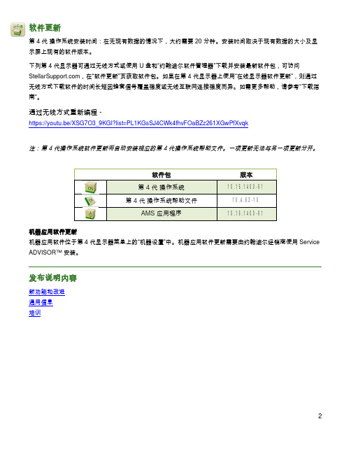
软件更新第 4 代 操作系统安装时间:在无现有数据的情况下,大约需要 20 分钟。
安装时间取决于现有数据的大小及显示屏上现有的软件版本。
下列第 4 代显示器可通过无线方式或使用 U 盘和“约翰迪尔软件管理器”下载并安装最新软件包,可访问 ,在“软件更新”页获取软件包。
如果在第 4 代显示器上使用“在线显示器软件更新”,则通过无线方式下载软件的时间长短因蜂窝信号覆盖强度或无线互联网连接强度而异。
如需更多帮助,请参考“下载指南”。
通过无线方式重新编程 -https://youtu.be/XSG7O3_9KGI?list=PL1KGsSJ4CWk4fhvFOaBZz261XGwPfXvqk注:第 4 代操作系统软件更新将自动安装相应的第 4 代操作系统帮助文件。
一项更新无法与另一项更新分开。
机器应用软件更新机器应用软件位于第 4 代显示器菜单上的“机器设置”中。
机器应用软件更新需要由约翰迪尔经销商使用 Service ADVISOR™ 安装。
发布说明内容新功能和改进通用信息培训软件包版本第 4 代 操作系统10.16.1400-91第 4 代 操作系统帮助文件10.4.63-10AMS 应用程序10.16.1400-91新功能和改进屏幕操作手册 -• 在显示器上的“帮助中心”应用程序中,新增了第4 代显示器的《操作手册》。
这部分内容将根据将来软件的更新需要而继续更新。
补充的屏幕帮助内容,可从“帮助中心”获得。
注:操作前,请认真阅读最新的《操作手册》。
如需最新版手册,请与经销商联系或访问。
导航 -• 驾驶员现在能在导航应用程序中创建“直线轨迹”和 “AB 曲线”的复制轨迹。
“复制轨迹”用来复制当前处于激活状态的导航轨迹。
新的复制轨迹的名称默认为是原始轨迹的名称加上(1)。
例如,轨迹“West”的复制轨迹的默认名称为 “West(1)”。
选择轨迹名称输入框修改轨迹名称。
新轨迹可以在机器上居中,或者向左或向右变换位置。

Dell PowerEdge R420xr Getting Started GuideRegulatory Model: E27S SeriesRegulatory Type: E27S001Notes, Cautions, and WarningsNOTE: A NOTE indicates important information that helps you make better use of your computer.CAUTION: A CAUTION indicates either potential damage to hardware or loss of data and tells you how to avoid the problem.WARNING: A WARNING indicates a potential for property damage, personal injury, or death.Copyright © 2014 Dell Inc. All rights reserved. This product is protected by U.S. and international copyright and intellectual property laws. Dell™ and the Dell logo are trademarks of Dell Inc. in the United States and/or other jurisdictions. All other marks and names mentioned herein may be trademarks of their respective companies.2013 – 11Rev. A00Installation And ConfigurationWARNING: Before performing the following procedure, review the safety instructions that came with the system.Unpacking A Rack SystemUnpack your system and identify each item.Assemble the rails and install the system in the rack following the safety instructions and the rack installation instructions provided with your system.Figure 1. Installing the System in a Rack.Optional—Connecting The Keyboard, Mouse, And MonitorFigure 2. Optional—Connecting the Keyboard, Mouse, and MonitorConnect the keyboard, mouse, and monitor (optional).3The connectors on the back of your system have icons indicating which cable to plug into each connector. Be sure to tighten the screws (if any) on the monitor's cable connector. Connecting The Power Cable(s)Figure 3. Connecting the Power Cable(s)Connect the system’s power cable(s) to the system and, if a monitor is used, connect the monitor’s power cable to the monitor.Securing The Power Cable(s)Figure 4. Securing the Power Cable(s)Bend the system power cable(s), as shown in the illustration, and attach to the cable strap.Plug the other end of the power cable(s) into a grounded electrical outlet or a separate power source such as an uninterruptible power supply (UPS) or a power distribution unit (PDU).4Turning On The SystemFigure 5. Turning on the SystemPress the power button on the system. The power indicator should light.Installing The Optional BezelFigure 6. Installing the Optional BezelInstall the bezel (optional).Complete The Operating System SetupIf you purchased a system with a pre-installed operating system, see the operating system documentation that shipped with your system. To install an operating system for the first time, see the installation and configuration documentation for your operating system. Be sure that the operating system is installed before installing hardware or software not purchased with the system.NOTE: For latest information on supported operating systems, see /ossupport.5Dell Software License AgreementBefore using your system, read the Dell Software License Agreement that came with your system. You must consider any media of Dell-installed software as BACKUP copies of the software installed on your system’s hard drive. If you do not accept the terms of the agreement, call the customer assistance telephone number. For customers in the United States, call 800-WWW-DELL (800-999-3355). For customers outside the United States, see /support and select your country or region from the top left of the page.Other Information You May NeedWARNING: See the safety and regulatory information that shipped with your system. Warranty information may be included within this document or as a separate document.•The Owner’s Manual provides information about system features and describes how to troubleshoot the system and install or replace system components. This document is available online at / support/manuals.•The rack documentation included with your rack solution describes how to install your system into a rack, if required.•Any media that ships with your system that provides documentation and tools for configuring and managing your system, including those pertaining to the operating system, system management software, system updates, and system components that you purchased with your system.NOTE: Always check for updates on /support/manuals and read the updates first because they often supersede information in other documents.NOTE: When upgrading your system, it is recommended that you download and install the latest BIOS, driver, and systems management firmware on your system from /support.Obtaining Technical AssistanceIf you do not understand a procedure in this guide or if the system does not perform as expected, see your system Owner’s Manual. Dell offers comprehensive hardware training and certification. See/training for more information. This service may not be offered in all locations.NOM Information (Mexico Only)The following information is provided on the device described in this document in compliance with the requirements of the official Mexican standards (NOM):Importer:Dell Inc. de México, S.A. de C.V.Paseo de la Reforma 2620 -11º PisoCol. Lomas Altas11950 México, D.F.Model number:E27SSupply voltage:100 V CA–240 V CAFrequency:50 Hz/60 Hz6Current consumption:7.4 A – 3.7 A (X2) (with 550 W Redundant AC Power Supply Unit)Technical SpecificationsNOTE: The following specifications are only those required by law to ship with your system. For a complete and current listing of the specifications for your system, go to /support .789。

IBM MQVersion 9.0Quick Start GuideUse this guide to get started with IBM MQ Version 9.0.National Language Version:To obtain the Quick Start Guide in other languages, print the language-specific PDF from the Quick Start DVD.Product overviewIBM ®MQ is robust messaging middleware that simplifies and accelerates the integration of diverse applications and business data across multiple platforms. IBM MQ facilitates the assured, secure and reliable exchange of information betweenapplications, systems, services and files by sending and receiving message data via messaging queues, thereby simplifying the creation and maintenance of business applications. It delivers Universal Messaging with a broad set of offerings to meet enterprise-wide messaging needs, and can be deployed across a range of different environments including on-premise, in cloud environments and supporting hybrid cloud deployments.IBM MQ supports a number of different application programming interfaces (APIs) including Message Queue Interface (MQI),Java ™Message Service (JMS), .NET, IBM MQ Light and MQTT.Product documentation for all versions of IBM MQ is available at /software/integration/wmq/library/.Specifically, the IBM MQ Version 9.0 product documentation is also available in IBM Knowledge Center(/support/knowledgecenter/SSFKSJ_9.0.0/com.ibm.mq.helphome.v90.doc/WelcomePagev9r0.htm).Service and support information is provided in the documentation.Information about how to use MQ Explorer can be accessed either from within MQ Explorer or in the product documentation.3Step 3: Review the installation architectureIBM MQ architectures range from simple architectures that use a single queue manager, to more complex networks of interconnected queue managers. For more information about planning your IBM MQ architecture, see the Planning section of the product documentation.For links to additional information, see the IBM MQ product page in IBM Knowledge Center (/support/knowledgecenter/SSFKSJ/).4Step 4: Install the productFor installation instructions for IBM MQ on AIX ®, HP-UX, Linux, Solaris, IBM i, or Microsoft Windows, and for details of the hardware and software configurations that are required, refer to the Installing section of the product documentation.For installation instructions for IBM MQ on z/OS ®, and for details of the hardware and software configurations that are required, see the Installing IBM MQ for z/OS section of the product documentation.IBM®5Step 5: Get startedThe Getting Started scenario in the Scenarios section of the product documentation explains how to get started with IBMMQ on Windows. Use this scenario if you have not used IBM MQ before and want to get started quickly.Further scenarios help you to configure or use product features by taking you through the appropriate task steps. The scenarios include links to other content that helps you to gain a better understanding of the area in which you are interested.More informationFor more information about IBM MQ, see the following resources:Product readme fileThe product readme file (readme.html) is included on the product media and is installed when you install productcomponents. The latest version is available on the product readmes web page (/support/docview.wss?rs=171&uid=swg27006097).IBM Support PortalSupport information available through IBM Support Portal includes the following resources:v Support technotes (/support/search.wss?q=websphere+mq)v Available downloads and other resources (/support/entry/portal/product/websphere/websphere_mq?productContext=24824631)v Systems Middleware Support Social Media Channels (/support/docview.wss?uid=swg21410956#2IBM MQ Version 9.0 Licensed Materials - Property of IBM. © Copyright IBM Corp. 2006, 2016. U.S. Government Users Restricted Rights - Use, duplication or disclosure restricted by GSA ADP Schedule Contract with IBM Corp. IBM, the IBM logo, , AIX, Passport Advantage, WebSphere®and z/OS are trademarks or registered trademarks of International Business Machines Corp., registered in many jurisdictions worldwide. Java and all Java-based trademarks and logos are trademarks or registered trademarks of Oracle and/or its affiliates. Linux is a registered trademark of Linus Torvalds in the United States, other countries, or both. Microsoft, Windows, and the Windows logo are trademarks of Microsoft Corporation in the United States, other countries, or both. Other product and service names might be trademarks of IBM or other companies. A current list of IBM trademarks is available on the Web at “Copyright and trademark information” (/legal/copytrade.shtml).Part Number:CF4IWMLPrinted in Ireland。


G Series LCD MonitorG244F E2 (3BB4) G244PF E2 (3BB4) User GuideContentsGetting Started (3)Package Contents (3)Installing the Monitor Stand (4)Adjusting the Monitor (6)Monitor Overview (8)Connecting the Monitor to PC (11)OSD Setup (13)Navi Key (13)Hot Key (14)OSD Menus (15)Gaming (15)Professional (17)Image (18)Input Source (19)Navi Key (19)Setting (20)Specifications (22)Preset Display Modes (24)Troubleshooting (25)Safety Instructions (26)TÜV Rheinland Certification (28)Regulatory Notices (29)RevisionV1.0, 2023/09Getting StartedThis chapter provides you with the information on hardware setup procedures. While connecting devices, be careful in holding the devices and use a grounded wrist strap to avoid static electricity.∙Contact your place of purchase or local distributor if any of the items is damaged or missing.∙Package contents may vary by country.∙The included power cord is exclusively for this monitor and should not be used with other products.Installing the Monitor Stand1. Leave the monitor in its protective packaging. Align the stand bracket to the monitor groove.2. Tighten the stand bracket with screws.3. Connect the base to the stand and tighten the base screw to secure the base.4. Make sure the stand assembly is properly installed before setting the monitor upright.G244F E2G244PF E2Important ∙Place the monitor on a soft, protected surface to avoid scratching the display panel. ∙Do not use any sharp objects on the panel. ∙The groove for installing the stand bracket can also be used for wall mount. Please contact your dealer for proper wall mount kit. ∙This product comes with NO protective film to be removed by the user! Any mechanical damages to the product including removal of the polarizing film mayAdjusting the MonitorThis monitor is designed to maximize your viewing comfort with its adjustment capabilities.⚠ImportantAvoid touching the display panel when adjusting the monitor.G244F E2G244PF E2Monitor Overview G244F E2G244PF E2Connecting the Monitor to PC1. Turn off your computer.2. Connect the video cable from the monitor to your computer.3. Assemble the external power supply & power cord. (Figure A)4. Connect the external power supply to the monitor power jack. (Figure B)5. Plug the power cord into the electrical outlet. (Figure C)6. Turn on the monitor. (Figure D)7. Power on the computer and the monitor will auto detect the signal source. G244F E2G244PF E2OSD SetupThis chapter provides you with essential information on OSD Setup.⚠ImportantAll information is subject to change without prior notice.Navi KeyThe monitor comes with a Navi Key, a multi-directional control that helps navigate the On-Screen Display (OSD) menu.G244F E2G244PF E2Up/Down/Left/Right:∙selecting function menus and items∙adjusting function values∙entering into/exiting from function menusPress (OK):∙launching the On-Screen Display (OSD)∙entering submenus∙confirming a selection or settingHot Key∙Users may enter into preset function menus by moving the Navi Key up, down, left or right when the OSD menu is inactive.∙Users may customize their own Hot Keys to enter into different function menus.OSD Menus⚠ImportantThe following settings will be grayed out when HDR signals are received:∙Night Vision ∙MPRT∙Low Blue Light∙HDCR ∙Brightness ∙Contrast3.0A 3.0A* Based on CIE1976 test standards.Preset Display Modes ImportantTroubleshootingThe power LED is off.• Press the monitor power button again.• Check if the monitor power cable is properly connected.No image.• Check if the computer graphics card is properly installed.• Check if the computer and monitor are connected to electrical outlets and are turned on.• Check if the monitor signal cable is properly connected.• The computer may be in Standby mode. Press any key to activate the monitor. The screen image is not properly sized or centered.• Refer to Preset Display Modes to set the computer to a setting suitable for the monitor to display.No Plug & Play.• Check if the monitor power cable is properly connected.• Check if the monitor signal cable is properly connected.• Check if the computer and graphics card are Plug & Play compatible. The icons, font or screen are fuzzy, blurry or have color problems.• Avoid using any video extension cables.• Adjust brightness and contrast.• Adjust RGB color or tune color temperature.• Check if the monitor signal cable is properly connected.• Check for bent pins on the signal cable connector.The monitor starts flickering or shows waves.• Change the refresh rate to match the capabilities of your monitor.• Update your graphics card drivers.• Keep the monitor away from electrical devices that may cause electromagnetic interference (EMI).Safety Instructions∙Read the safety instructions carefully and thoroughly.∙All cautions and warnings on the device or User Guide should be noted.∙Refer servicing to qualified personnel only.Power∙Make sure that the power voltage is within its safety range and has been adjusted properly to the value of 100~240V before connecting the device to the power outlet. ∙If the power cord comes with a 3-pin plug, do not disable the protective earth pin from the plug. The device must be connected to an earthed mains socket-outlet.∙Please confirm the power distribution system in the installation site shall provide the circuit breaker rated 120/240V, 20A (maximum).∙Always disconnect the power cord or switch the wall socket off if the device would be left unused for a certain time to achieve zero energy consumption.∙Place the power cord in a way that people are unlikely to step on it. Do not place anything on the power cord.∙If this device comes with an adapter, use only the MSI provided AC adapter approved for use with this device.Environment∙To reduce the possibility of heat-related injuries or of overheating the device, do not place the device on a soft, unsteady surface or obstruct its air ventilators.∙Use this device only on a hard, flat and steady surface.∙To prevent the device from tipping over, secure the device to a desk, wall or fixed object with an anti-tip fastener that helps to properly support the device and keep it safe in place.∙To prevent fire or shock hazard, keep this device away from humidity and high temperature.∙Do not leave the device in an unconditioned environment with a storage temperature above 60℃ or below -20℃, which may damage the device.∙The maximum operating temperature is around 40℃.∙When cleaning the device, be sure to remove the power plug. Use a piece of soft cloth rather than industrial chemical to clean the device. Never pour any liquid into the opening; that could damage the device or cause electric shock.∙Always keep strong magnetic or electrical objects away from the device.∙If any of the following situations arises, get the device checked by service personnel:• The power cord or plug is damaged.• Liquid has penetrated into the device.• The device has been exposed to moisture.• The device does not work well or you can not get it working according to the User Guide.• The device has dropped and damaged.• The device has obvious sign of breakage.TÜV Rheinland CertificationTÜV Rheinland Low Blue Light CertificationBlue light has been shown to cause eye fatigueand discomfort. MSI now offers monitors with TÜVRheinland Low Blue Light certification to ensureusers’ eye comfort and well-being. Please followthe instructions below to reduce the symptoms fromextended exposure to the screen and blue light.∙Place the screen 20 – 28 inches (50 – 70 cm) away from your eyes and a little below eye level.∙Consciously blinking the eyes every now and then will help to reduce eye strain after extended screen time.∙Take breaks for 20 minutes every 2 hours.∙Look away from the screen and gaze at a distant object for at least 20 seconds during breaks.∙Make stretches to relieve body fatigue or pain during breaks.∙Turn on the optional Low Blue Light function.TÜV Rheinland Flicker Free Certification∙TÜV Rheinland has tested this product toascertain whether the display produces visibleand invisible flicker for the human eye andtherefore strains the eyes of users.∙TÜV Rheinland has defined a catalogue oftests, which sets out minimum standardsat various frequency ranges. The test catalogue is based on internationally applicable standards or standards common within the industry and exceeds these requirements.∙The product has been tested in the laboratory according to these criteria.∙The keyword “Flicker Free” confirms that the device has no visible and invisible flicker defined in this standard within the range of 0 - 3000 Hz under various brightness settings.∙The display will not support Flicker Free when Anti Motion Blur/MPRT is enabled. (The availability of Anti Motion Blur/MPRT varies by products.)Regulatory NoticesCE ConformityThis device complies with the requirements set out in the Council Directive on the Approximation of the Laws of the Member States relating to Electromagnetic Compatibility (2014/30/EU), Low-voltage Directive (2014/35/EU), ErP Directive (2009/125/EC) and RoHS directive (2011/65/EU). This product has been tested and found to comply with the harmonized standards for Information Technology Equipment published under Directives of Official Journal of the European Union.FCC-B Radio Frequency Interference StatementThis equipment has been tested and found to comply with the limitsfor a Class B digital device, pursuant to Part 15 of the FCC Rules.These limits are designed to provide reasonable protection against harmful interference in a residential installation. This equipment generates, uses and can radiate radio frequency energy and, ifnot installed and used in accordance with the instruction manual, may cause harmful interference to radio communications. However, there is no guarantee that interference will not occur in a particular installation. If this equipment does cause harmful interference to radio or television reception, which can be determined by turning the equipment off and on, the user is encouraged to try to correct the interference by one or more of the measures listed below:∙Reorient or relocate the receiving antenna.∙Increase the separation between the equipment and receiver.∙Connect the equipment into an outlet on a circuit different from that to which the receiver is connected.∙Consult the dealer or an experienced radio/television technician for help. Notice 1The changes or modifications not expressly approved by the party responsible for compliance could void the user’s authority to operate the equipment. Notice 2Shielded interface cables and AC power cord, if any, must be used in order to comply with the emission limits.This device complies with Part 15 of the FCC Rules. Operation is subject to the following two conditions:1. This device may not cause harmful interference, and2. This device must accept any interference received, including interference that may cause undesired operation.MSI Computer Corp.901 Canada Court, City of Industry, CA 91748, USA(626) 913-0828WEEE StatementUnder the European Union (“EU”) Directive on Waste Electrical and Electronic Equipment, Directive 2012/19/EU, products of “electrical and electronic equipment” cannot be discarded as municipal waste anymoreand manufacturers of covered electronic equipment will be obligated totake back such products at the end of their useful life. Chemical Substances InformationIn compliance with chemical substances regulations, such as the EU REACH Regulation (Regulation EC No. 1907/2006 of the European Parliament and the Council), MSI provides the information of chemical substances in products at: https:///global/indexRoHS StatementJapan JIS C 0950 Material DeclarationA Japanese regulatory requirement, defined by specification JIS C 0950, mandates that manufacturers provide material declarations for certain categories of electronic products offered for sale after July 1, 2006.https:///global/Japan-JIS-C-0950-Material-Declarations India RoHSThis product complies with the “India E-waste (Management and Handling) Rule 2016” and prohibits use of lead, mercury, hexavalent chromium, polybrominated biphenyls or polybrominated diphenyl ethers in concentrations exceeding 0.1 weight % and 0.01 weight % for cadmium, except for the exemptions set in Schedule 2 of the Rule. Turkey EEE RegulationConforms to the EEE Regulations of the Republic Of Turkey Ukraine Restriction of Hazardous SubstancesThe equipment complies with requirements of the Technical Regulation, approved by the Resolution of Cabinet of Ministry of Ukraine as of 10 March 2017, № 139, in terms of restrictions for the use of certain dangerous substances in electrical and electronic equipment.Vietnam RoHSAs from December 1, 2012, all products manufactured by MSI comply with Circular 30/2011/TT-BCT temporarily regulating the permitted limits for a number of hazardous substances in electronic and electric products.31Green Product Features∙Reduced energy consumption during use and stand-by ∙Limited use of substances harmful to the environment and health∙Easily dismantled and recycled ∙Reduced use of natural resources by encouraging recycling ∙Extended product lifetime through easy upgrades ∙Reduced solid waste production through take-back policy Environmental Policy ∙The product has been designed to enable proper reuse of parts and recycling and should not be thrown away at its end of life. ∙Users should contact the local authorized point of collection for recycling and disposing of their end-of-life products. ∙Visit the MSI website and locate a nearby distributor for further recycling information. ∙*******************************************************************disposal, take-back, recycling, and disassembly of MSI products.Warning!Overuse of screens is likely to affect eyesight.Recommendations: 1. Take a 10-minute break for every 30 minutes of screen time. 2. Children under 2 years of age should have no screen time. For children aged 2 years and over, screen time should be limited to less than one hour per day.Copyright and Trademarks Notice Copyright © Micro-Star Int’l Co., Ltd. All rights reserved. The MSI logo used is a registered trademark of Micro-Star Int’l Co., Ltd. All other marks and names mentioned may be trademarks of their respective owners. No warranty as to accuracy or completeness is expressed or implied. MSI reserves the right to make changes to this document without prior notice.The terms HDMI™, HDMI™ High-Definition Multimedia Interface, HDMI™ Trade dress and the HDMI™ Logos are trademarks or registered trademarks of HDMI™ Licensing Administrator, Inc.Technical Support If a problem arises with your product and no solution can be obtained from the user’s manual, please contact your place of purchase or local distributor. Alternatively,please visit https:///support/ for further guidance.。

目录数字媒体片上系统TMS320DM6467T (2)ARM 子系统 (2)DSP子系统 (3)设备的配置 (3)电源供应 (3)复位 (3)中断 (3)SRM CPU 中断 (4)异步EMIFA (4)DDR2存储器控制器 (4)VIDEO 端接口(VPIF) (4)传送数据流接口(TSIF) (5)视频数据变换引擎(VDCE) (5)HPI (5)USB 2.0 (5)UART通用异步收发器 (6)Inter-Integrated Circuit (I2C) (6)脉宽调节器(PWM) (6)定时器 (6)IEEE 1149.1 JTAG (7)DEVICE CONFIGURATION (7)系统模块寄存器 (7)电源因素 (7)时钟因素 (8)启动顺序 (8)复位配置 (9)复位后的配置 (9)复用管脚的配置 (9)调试 (10)数字媒体片上系统TMS320DM6467TTMS320DM6467T利用TI’s DaVinci™技术满足下一代嵌入式设备的网络媒体编码解码应用处理需求。
ARM 子系统用于控制设备,通常用来负责配置和控制设备。
包括DSP子系统,VPSS子系统,和大量外设和内部存储器。
ARM926EJ-S精简指令,ARMv5TEJ16/32位命令设置,cp15,16K命令缓存,8K数据缓存,写缓存器,Memory Management Unit (MMU),32K Tightly-Coupled Memory (TCM) RAM 32位带宽访问,8K内部ROM(ARM bootloader for non-EMIFA boot options),Embedded Trace Module and Embedded Trace Buffer (ETM/ETB),ARM中断控制,PLL控制,Power and Sleep Controller (PSC)。
DSP子系统C64x+CPU 8个功能单元,两个寄存器文件,两个数据路径,两个通用寄存器文件(A,B)每个包含32个32bit寄存器。

版本:V1.0 DM6467T开发环境使用指南嵌云阁主2017.9版本历史信息目录DM6467T开发环境使用指南 (1)1 简介 (1)2 虚拟机使用 (3)2.1 Vmware网络配置 (3)2.2 将windows下的工作目录共享给Linux (3)2.3 Samba使用 (4)2.4 Ssh服务使用 (5)2.5 Tftp服务 (5)2.6 Nfs服务 (5)2.7 ftp服务 (5)2.8 telnet服务 (6)2.9 http服务 (6)3 DVS6467T开发环境使用 (7)3.1 DVSDK编译 (7)3.2 Uboot编译 (8)3.3 Linux内核编译 (8)4 仿真器使用 (9)4.1 用仿真器解决内核加载问题 (9)5 在ccs7下进行DM6467的开发 (13)5.1 测试工程 (13)5.1.1 创建测试工程 (13)5.1.2 GEL配置 (14)5.1.3 启动dsp调试 (15)5.2 实用的代码分析与编写 (16)5.3 Linux内核编译 (17)5.4 编译驱动模块 (20)6 在ccs7下进行Linux应用程序的开发 ................................................. 错误!未定义书签。
6.1 Makefile应用程序...................................................................... 错误!未定义书签。
1简介对于嵌入式开发而言,入门最大的难度之一在于开发环境的搭建。
《DM6467开发环境V1.0》整合了TI发布的DM6467T开发工具,将其整合到一个VMVare虚拟机中,同时使用CCS做为开发工具,将各种命令行的繁琐隐藏到IDE的背后。
CCS是以Elipse为基础的IDE,不仅可以完成Linux内核及应用程序的编译,还可以使用仿真器进行硬件的调试,实现Linux内核及驱动的调试,实现板载应用程序的调试。

DU-05348-001_v6.0 | February 2014Installation and Verification on Mac OS XTABLE OF CONTENTS Chapter 1. Introduction (1)1.1. System Requirements (1)1.2. About This Document (2)Chapter 2. Prerequisites (3)2.1. CUDA-capable GPU (3)2.2. Mac OS X Version (3)2.3. Command-Line T ools (3)Chapter 3. Installation (5)3.1. Download (5)3.2. Install (5)3.3. Uninstall (6)Chapter 4. Verification (7)4.1. Driver (7)4.2. Compiler (7)4.3. Runtime (8)Chapter 5. Additional Considerations (10)CUDA™ is a parallel computing platform and programming model invented by NVIDIA. It enables dramatic increases in computing performance by harnessing the power of the graphics processing unit (GPU).CUDA was developed with several design goals in mind:‣Provide a small set of extensions to standard programming languages, like C, that enable a straightforward implementation of parallel algorithms. With CUDA C/C++, programmers can focus on the task of parallelization of the algorithms rather than spending time on their implementation.‣Support heterogeneous computation where applications use both the CPU and GPU. Serial portions of applications are run on the CPU, and parallel portions are offloaded to the GPU. As such, CUDA can be incrementally applied to existingapplications. The CPU and GPU are treated as separate devices that have their own memory spaces. This configuration also allows simultaneous computation on the CPU and GPU without contention for memory resources.CUDA-capable GPUs have hundreds of cores that can collectively run thousands of computing threads. These cores have shared resources including a register file and a shared memory. The on-chip shared memory allows parallel tasks running on these cores to share data without sending it over the system memory bus.This guide will show you how to install and check the correct operation of the CUDA development tools.1.1. System RequirementsTo use CUDA on your system, you need to have:‣ a CUDA-capable GPU‣Mac OS X 10.8 or later‣the gcc or Clang compiler and toolchain installed using Xcode‣the NVIDIA CUDA Toolkit (available from the CUDA Download page)Introduction T able 1 Mac Operating System Support in CUDA 6.0Before installing the CUDA Toolkit, you should read the Release Notes, as they provide important details on installation and software functionality.1.2. About This DocumentThis document is intended for readers familiar with the Mac OS X environment andthe compilation of C programs from the command line. You do not need previous experience with CUDA or experience with parallel computation.2.1. CUDA-capable GPUTo verify that your system is CUDA-capable, under the Apple menu select AboutThis Mac, click the More Info … button, and then select Graphics/Displays under the Hardware list. There you will find the vendor name and model of your graphics card.If it is an NVIDIA card that is listed on the CUDA-supported GPUs page, your GPU is CUDA-capable.The Release Notes for the CUDA Toolkit also contain a list of supported products.2.2. Mac OS X VersionThe CUDA Development Tools require an Intel-based Mac running Mac OSX v. 10.8 or later. To check which version you have, go to the Apple menu on the desktop and select About This Mac.2.3. Command-Line T oolsThe CUDA Toolkit requires that the native command-line tools (gcc, clang,...) are already installed on the system.To install those command-line tools, Xcode must be installed first. Xcode is available from the Mac App Store.Once Xcode is installed, the command-line tools can be installed by launching Xcode and following those steps:1.Xcode > Preferences... > Downloads > Components2.Install the Command Line Tools packageAlternatively, you can install the command-line tools from the Terminal window by typing the following command: xcode-select --install.PrerequisitesYou can verify that the toolchain is installed by entering the command /usr/bin/cc --help from a Terminal window.3.1. DownloadOnce you have verified that you have a supported NVIDIA GPU, a supported version the MAC OS, and gcc, you need to download the NVIDIA CUDA Toolkit.The NVIDIA CUDA Toolkit is available at no cost from the main CUDA Downloads page. It contains the driver and tools needed to create, build and run a CUDA application as well as libraries, header files, CUDA samples source code, and other resources.The download can be verified by comparing the posted MD5 checksum with that of the downloaded file. If either of the checksums differ, the downloaded file is corrupt and needs to be downloaded again.To calculate the MD5 checksum of the downloaded file, run the following:$ openssl md5 <file>3.2. InstallUse the following procedure to successfully install the CUDA driver and the CUDA toolkit. The CUDA driver and the CUDA toolkit must be installed for CUDA to function. If you have not installed a stand-alone driver, install the driver provided with the CUDA Toolkit.Choose which packages you wish to install. The packages are:‣CUDA Driver: This will install /Library/Frameworks/CUDA.framework and the UNIX-compatibility stub /usr/local/cuda/lib/libcuda.dylib that refers to it.‣CUDA Toolkit: The CUDA Toolkit supplements the CUDA Driver with compilers and additional libraries and header files that are installed into /Developer/ NVIDIA/CUDA-6.0 by default. Symlinks are created in /usr/local/cuda/pointing to their respective files in /Developer/NVIDIA/CUDA-6.0/. PreviousInstallationinstallations of the toolkit will be moved to /Developer/NVIDIA/CUDA-#.# tobetter support side-by-side installations.‣CUDA Samples (read-only): A read-only copy of the CUDA Samples is installed in /Developer/NVIDIA/CUDA-6.0/samples. Previous installations of the samples will be moved to /Developer/NVIDIA/CUDA-#.#/samples to better support side-by-side installations.Set up the required environment variables:export PATH=/Developer/NVIDIA/CUDA-6.0/bin:$PATHexport DYLD_LIBRARY_PATH=/Developer/NVIDIA/CUDA-6.0/lib:$DYLD_LIBRARY_PATHIn order to modify, compile, and run the samples, the samples must also be installed with write permissions. A convenience installation script is provided: cuda-install-samples-6.0.sh. This script is installed with the cuda-samples-6-0 package.3.3. UninstallThe CUDA Driver, Toolkit and Samples can be uninstalled by executing the uninstall script provided with the Toolkit:/Developer/NVIDIA/CUDA-6.0/bin/uninstallBefore continuing, it is important to verify that the CUDA toolkit can find and communicate correctly with the CUDA-capable hardware. To do this, you need to compile and run some of the included sample programs.Ensure the PATH and DYLD_LIBRARY_PATH variables are set correctly.4.1. DriverIf the CUDA Driver is installed correctly, the CUDA kernel extension (/System/ Library/Extensions/CUDA.kext) should be loaded automatically at boot time. To verify that it is loaded, use the commandkextstat | grep -i cuda4.2. CompilerThe installation of the compiler is first checked by running nvcc -V in a terminal window. The nvcc command runs the compiler driver that compiles CUDA programs. It calls the host compiler for C code and the NVIDIA PTX compiler for the CUDA code.On Mac OS 10.8 with XCode 5, nvcc must be invoked with --ccbin=path-to-clang-executable. There are some features that are not yet supported: Clang languageextensions (see /docs/LanguageExtensions.html), LL VM libc++ (only GNU libstdc++ is currently supported), language features introduced in C++11, the __global__ function template explicit instantiation definition, and 32-bitarchitecture cross-compilation.The NVIDIA CUDA Toolkit includes CUDA sample programs in source form. To fully verify that the compiler works properly, a couple of samples should be built. After switching to the directory where the samples were installed, type:Verificationmake -C 0_Simple/vectorAddmake -C 0_Simple/vectorAddDrvmake -C 1_Utilities/deviceQuerymake -C 1_Utilities/bandwidthTestThe builds should produce no error message. The resulting binaries will appear under <dir>/bin/x86_64/darwin/release. To go further and build all the CUDA samples, simply type make from the samples root directory.4.3. RuntimeAfter compilation, go to bin/x86_64/darwin/release and run deviceQuery. Ifthe CUDA software is installed and configured correctly, the output for deviceQuery should look similar to that shown in Figure 1.Figure 1 Valid Results from deviceQuery CUDA SampleNote that the parameters for your CUDA device will vary. The key lines are the first and second ones that confirm a device was found and what model it is. Also, the next-to-last line, as indicated, should show that the test passed.Running the bandwidthTest sample ensures that the system and the CUDA-capable device are able to communicate correctly. Its output is shown in Figure 2VerificationFigure 2 Valid Results from bandwidthT est CUDA SampleNote that the measurements for your CUDA-capable device description will vary from system to system. The important point is that you obtain measurements, and that the second-to-last line (in Figure 2) confirms that all necessary tests passed.Should the tests not pass, make sure you have a CUDA-capable NVIDIA GPU on your system and make sure it is properly installed.If you run into difficulties with the link step (such as libraries not being found), consult the Release Notes found in the doc folder in the CUDA Samples directory.To see a graphical representation of what CUDA can do, run the particles executable.Now that you have CUDA-capable hardware and the NVIDIA CUDA Toolkit installed, you can examine and enjoy the numerous included programs. To begin using CUDA to accelerate the performance of your own applications, consult the CUDA C Programming Guide.A number of helpful development tools are included in the CUDA Toolkit to assistyou as you develop your CUDA programs, such as NVIDIA® Nsight™ Eclipse Edition, NVIDIA Visual Profiler, cuda-gdb, and cuda-memcheck.For technical support on programming questions, consult and participate in the Developer Forums.NoticeALL NVIDIA DESIGN SPECIFICATIONS, REFERENCE BOARDS, FILES, DRAWINGS, DIAGNOSTICS, LISTS, AND OTHER DOCUMENTS (TOGETHER AND SEPARATEL Y, "MATERIALS") ARE BEING PROVIDED "AS IS." NVIDIA MAKES NO WARRANTIES, EXPRESSED, IMPLIED, STATUTORY, OR OTHERWISE WITH RESPECT TO THE MATERIALS, AND EXPRESSL Y DISCLAIMS ALL IMPLIED WARRANTIES OF NONINFRINGEMENT, MERCHANTABILITY, AND FITNESS FOR A PARTICULAR PURPOSE.Information furnished is believed to be accurate and reliable. However, NVIDIA Corporation assumes no responsibility for the consequences of use of such information or for any infringement of patents or other rights of third parties that may result from its use. No license is granted by implication of otherwise under any patent rights of NVIDIA Corporation. Specifications mentioned in this publication are subject to change without notice. This publication supersedes and replaces all other information previously supplied. NVIDIA Corporation products are not authorized as critical components in life support devices or systems without express written approval of NVIDIA Corporation.TrademarksNVIDIA and the NVIDIA logo are trademarks or registered trademarks of NVIDIA Corporation in the U.S. and other countries. Other company and product names may be trademarks of the respective companies with which they are associated. Copyright© 2009-2014 NVIDIA Corporation. All rights reserved.。

DM6437应用向DSP/BIOS中增加硬中断【整理者】【提供者】43r3【详细说明】DM6437应用向DSP/BIOS中增加硬中断64+的中断系统和以往的不同,中断是基于事件的。
整个硬件CPU接收15个中断,但中断源可以支持最多128个。
64+将中断源视为事件"Event",128个事件可以分别通过配置连接到15个CPU中断。
而128个事件每连续32个可以合并到四个固定的事件中,即Event0(对应事件号0-31)、Event1(对应事件号32-63)、Event2(对应事件号64-95)、Event3(对应事件号96-127)(实际最大有效中断源为124个)。
这样可以通过数量有限的CPU中断来管理大量的中断源,使用灵活。
DSP/BIOS默认将Event0-3分别对应到HWI_INT7-10四个中断号。
TI驱动通过注册Event到这四个事件,进而对应到相应中断。
在中断HWI_INT7-10服务函数中再去判断具体是哪个事件触发的中断。
另外还有几个中断是系统硬件复位中断、NMI中断、预保留中断及仿真通讯中断。
HWI_INT4-6、HWI_INT13、HWI_INT15这5个中断是未使用中断。
用户增加中断服务的话,可以将事件号对应到这5个中断来实现。
以T1高32位定时中断为例,介绍一下DM6437应用中如何在DSP/BIOS操作系统中实现硬件中断。
首先用户需要将T1配置为双32位定时器,T1高32位定时器中断服务函数为 T1HIsr()。
将事件对应到中断HWI_INT5。
1 在DSP/BIOS图形配置界面下打开"Scheduling"->"HWI-Hardware Interrupu Service"。
2 下拉表中有15个中断。
观察各中断使用情况。
右键点击"HWI_INT5",弹出下拉菜单中选"Properties"进入中断属性编辑栏。


EverDrive-64 X7User Manual20.09.2020Features•Cyclone IV FPGA•64MB SDRAM•128KB battery backed ram•High quality 4-layers PCB with hard gold surface finish•USB port for development•Supports both PAL and NTSC systems•UltraCIC III with region auto detection•RTC support•Fast loading. Speed up to 23 Mbyte/s•Up to 1024 files per folder•Supports nes ROM format via built-in emulator•Gamepak saves support (SRAM, SRAM128Kbyte, EEPROM16k, EEPROM4k, FlashRam)•GameShark cheats•IPS/APS patchesInitial setup•Format SD card•Download OS-V3.xx.zip from •Unzip OS files to SD card•Copy ROM files to SD card. ROM files should be located outside of system folder (ED64)File Manager• A – Open directory or file menu• B – Back or Close•Z – Open main menu•Start – Run last played game•Left/Right – Switch page during file navigationUpper bar shows current page and total number of pages in the current folder. Bottom bar shows the full name of selected file.File MenuFile menu is used for file manipulating on SD card. Menu content is different depending on file type.Rom file menuThis menu is applied to v64, n64, z64 and ROM file extensions.Start GameCartridge will be configured to play selected game. Right after configuration game will be executed. After reset or power cycle the last selected game can be launched with START button.CheatsEdit cheat codes for selected file.Rom InfoShow ROM configuration: save type, ROM region, checksum, etc.Hex ViewOpen selected file in hex viewer.DeleteDelete file from disk.Text file menuThis menu is applied to *.txt file extension.It is used for loading cheats from text file. Loaded cheats will be applied to last selected game.Save-ram file menuAllows to copy current save-ram content to file, copy file to save-ram, check file date and size, delete file.Controller PAK file menuAllows to copy data from controller pak to file or visa versa.Image file menuAllows to set background from image file. File format should be jpg, 320x240, 150KB max size.Main MenuPush Z to open Main Menu.OptionsOptions->BackgroundSwitch on/off background image.Options->CheatsSwitch on/off cheat functions. This function requires expansion pak to be installed.Options->IPS/APSSwitch on/off automatic ips/aps patcher.Options->CRC CheckThis function checks rom checksum and fix it if incorrect. Console refused to boot ROMs with broken checksum. Increases ROM loading time a bit if enabled.Options->Hide Sys DirMake ED64 folder invisible in file browser.Options->RTC SetupSetup system time. It is used for games with RTC support and for save files dating.Recently PlayedList of recently played games for fast access.Random GameRun random game. Game seek will begin from currently open folder.CheatsEdit cheat codes for the last played game. Bottom bar shows the name of game codes will be applied to. Each code may have description, it is displayed at the top bar. To add description just put some text in txt file right after code or enter it manually in code editor. Each game may have its own set of codes, they are saved in ED64/cheats folder as text file and load automatically when game is played. The file name matches ROM name the codes are related to. Up to 34 codes can be applied at the same time. Alternative way to edit the codes for certain game is file menu, just hit the game in file manager. Cheats also can be loaded from text file selected in file manager. Cheats function requires expansion pak to be installed.CPak ManagerCopy data from controller pak to the file.CPak Manager->Save Cpak as controller numberSave data from controller pak to the ED64/save/controller-X.mpk where 'X' matches to the controller number.CPak Manager->Save Cpak as last played gameSave data from controller pak to the ED64/save/XXX.mpk where 'XXX' matches to the name of last played game.CPak Manager->FormatErase all data from controller pak.Data from .mpk files can be loaded back to controller pak using file menu.Device InfoInformation about the system.DiagnosticsDiagnostics menu checks cartridge health. All tests should be passed successfully if everything is fine.Special ROM configuration using save_db.txtDefault ROM settings can be changed in ED64/save_db.txt file.Setting listed below can be changed:1.Save type.2.RTC. Enable RTC function for certain ROM.3.Specify ROM region as “region free”. Allows to use native system region for ROM launch.Can be applied only to the ROMs without region lock.Configuration records consist of two parts:1.ROM identificator. It can be ROM ID or CRC HI, both can be obtained in Rom Info menu.2.Config number. It consists of two digits, first digit specify save type, second specifyROM config (RTC and region settings). ROM config values can be mixed by usingaddition (1+2=3 for rtc+region). Config number values listed below.Save types values:0 - OFF1 - EEPROM 4k2 - EEPROM 16K3 - SRAM4 - SRAM 768K5 - FLASHRAM6 - SRAM 128KROM config values:1 - Force RTC2 - Region freeExamples:0xABA51D09=12Save type=EEP4K, region free, ROM identification using CRC HIAF=51Save type=FLASHRAM, RTC, ROM identification using ROM IDIPS/APS patcherBuilt-in auto patcher engine allows to use ips and aps patches without using patching software. ROM stays unchanged on disk but patched in cart RAM.There two ways for path and ROM association:1.Patch name should match the ROM CRC HI and patch file should be located inED64/patcher folder. CRC HI can be obtained in "Rom Info" menu.2.Patch name should match the ROM name and patch file should be located at the samefolder with ROM.Third party emulatorsCartridge supports using third party emulators for playing games from other platforms. Emulator should be located in ED64/emu folder, file name should match the ROM extension from target platform. For example emulator for nes files should be stored asED64/emu/nes.v64Special ROM ID for homebrew devsUsing special ROM ID allows developers to specify ROM setting for their application. ROM ID should be set to 'ED' and then ROM settings can be specified in byte at offset 0x3F. Settings values matches the values in save_db.txt (0x12 for EEP4K+region free).Development resourcesPlease visit ED64 repository at github for reference source that can be used by homebrew developers to utilise SD card and USB capabilities via an ED64.https:///krikzz/ED64System folder structure/ED64system root/ED64/cheats Cheat files are located in this folder/ED64/emu Emulators/ED64/patcher Patch files for ips/aps auto patcher/ED64/save All save data are located in this folder/ED64/sys Cartridge system files/ED64/save_db.txt Special ROM configurations/ED64/OS64.v64ED64 OS coreLimitations•Cheat codes do not work without expansion pak•ROM region should match console region for best result. PAL ROM on NTSC system or NTSC rom on PAL system will produce not standard video mode, typically it causes color distortions or grayscale image, in some cases no image at all. This limitation is notaffect region-free ROMs without region locks (homebrew mostly).•Menu can display up to 1024 files per folder. Files over this limit will not be displayed.。

1.3 Directly mounted to electrical panel – preferred methodThe preferred installation is to mount the SPD directly to the electrical panel. For Type 4X applications, use the supplied mounting feet to secure the device.Figure 1. Preferred installation.1.4 Mounted to electrical panel with conduit – alternate methodAn alternate installation method is to install the SPD with a short piece straight conduit. Avoid using 90°conduit elbows and keep the conduit run as short and straight as possible. In this application, install the SPD as close as possible to the electrical panel. For Type 4X applications, use weatherproof conduit and fittings along with the supplied mounting feet to secure the device.Figure 2. Alternate installation.2. Wiring installationLocate the electrical system’s applicable wiring schematic from section 3. Wiring diagrams and refer to it while wiring the SPD.TURN OFF power to the electrical equipment being connected to the SPD in accordance with NEC, CEC, state, county and local codes for all safety ratings. Bussmann series SPDs covered in this guide are designed with internal overcurrent protection and do not require an externalovercurrent protective device (OCPD) unless otherwise required by NEC, UL and local electrical requirements to protect electrical conductors. NEC Article 310.15 (B) (16) defines the maximum rating of the OCPD required to protect the electrical conductors. NEC shows #10 AWG conductors at 60°C typically requiring a 1-pole (for single-phase systems), 2-pole (for split-phase systems) or 3-pole (for 3-phase systems) 30 A branch circuit breaker to protect SPD conductors.Twist and bind the SPD wires tightly together. Minimize overall lead length to optimize SPD performance. To maximize the SPD’sperformance, phase wire length should be less than 14” (35cm) twisted and bound together. To maximize performance for wire lengths longer than four inches, phase wires should be twisted once for each four inches of wire length.If the SPD is configured for remote monitoring (not available on allmodels), connect the Form C relay contact wiring to an alarm or building monitoring system. Refer to the installation manual (Publication No. 10679) for Form C relay ratings.Note: Utilization of Form C contacts is optional. Connecting Form C wires is not required for the SPD to operate.Tighten and recheck all connections and mounting before proceeding to section 4. Operation .BSPA Type 1 and Type 2 surge protective devices1. IntroductionThis quick start guide is for the installation, wiring and operation of the Bussmann™ series BSPA surge protective device (SPD). Only qualified personnel should perform this installation. For additional information regarding installation, wiring and operation of this device, refer to theinstallation manual (Publication No. 10679). If you require further information regarding a particular installation, application or maintenance activity, please *****************************************************************between 7:00 a.m. and 5:00 p.m. Central time, Monday-Friday. This quick start guide is not intended to cover all details, variations or combinations of the device’s storage, delivery, installation, operation or maintenance.1.1 Safety precautionsWARNINGWARNING – SHOCK HAZARD – DO NOT OPENAVERTISSEMENT – RISQUE DE CHOC – NE PAS OUVRIR WARNING NO SERVICEABLE PARTSATTENTION: AUCUNE PIÈCE REMPLACABLE OU RÉPARABLEA LICENSED/QUALIFIED ELECTRICIAN MUST COMPLETE ALL INSTRUCTIONS IN THIS GUIDE IN ACCORDANCE WITH THENATIONAL ELECTRICAL CODE (NEC ®), CANADIAN ELECTRICAL CODE (CEC), STATE, COUNTY AND LOCAL SAFETY RATINGS, OR OTHER APPLICABLE COUNTRY CODES. ALL APPLICABLE LOCAL ELECTRICAL CODES SUPERSEDE THESE INSTRUCTIONS.IMPROPER WIRING COULD CAUSE DEATH, INJURY AND/OREQUIPMENT DAMAGE. ONLY LICENSED/QUALIFIED ELECTRICIANS WHO ARE TRAINED IN THE INSTALLATION AND SERVICE OF ELECTRICAL SERVICES ARE TO INSTALL AND SERVICE THIS EQUIPMENT.CHECK THE VOLTAGE-RATING LABEL LOCATED ON THE SIDE OF THE SPD TO VERIFY THAT THE ELECTRICAL SYSTEM’S VOLTAGE AND WIRING CONFIGURATION ARE THE SAME AS THE SPD.CONDUCTING DIELECTRIC, MEGGAR, OR HI-POTENTIAL TESTING WITH THE SPD INSTALLED WILL CAUSE INTERNAL DAMAGE TO THE SPD. THE SPD WILL CAUSE THE TEST TO FAIL.IMPROPER INSTALLATION COULD CAUSE DEATH, INJURY AND EQUIPMENT DAMAGE. FOLLOW ALL WARNINGS AND CAUTIONS. COMPLETELY READ AND UNDERSTAND THE INFORMATION IN THIS GUIDE BEFORE ATTEMPTING TO INSTALL OR OPERATE THIS EQUIPMENT.ARC FLASH DURING INSTALLATION COULD CAUSE INJURY ORDEATH. USE APPROPRIATE SAFETY PRECAUTIONS AND PERSONAL PROTECTION EQUIPMENT FOR ARC FLASH PROTECTION.CHECK THE FACILITY’S GROUNDING SYSTEM. ALL GROUNDING, BONDING AND EARTHING PRACTICES MUST MEET NEC, CEC AND LOCAL APPROVED PRACTICES. A POOR GROUND, OR A GROUNDING / BONDING VIOLATION WILL SERIOUSLY AFFECT THE SPD’S ABILITY TO FUNCTION AS SPECIFIED.INSTALLING AN SPD THAT IS IMPROPERLY RATED FOR THEELECTRICAL SYSTEM VOLTAGE COULD CREATE A POTENTIALLY HAZARDOUS CONDITION, RESULTING IN INJURY OR EQUIPMENT DAMAGE.WHEN MOUNTING THE SPD OUTDOORS, USE WEATHERPROOF CONDUIT AND FITTINGS TO MAINTAIN THE ENCLOSURE’S NEMA RATING.FOR USE ON CIRCUITS DELIVERING UP TO 5000 RMS AMPS.CONVIENT Á DES CIRCUITS PRODUCISANT AU PLUS 5000 A EFF.1.2 Enclosure dimensionsRefer to the installation manual (Publication No. 10679) for unit size and dimensions.BSPA T ype 1 and T ype 2 surge protective devicesQuick start guide 10678Effective October 2017Eaton and Bussmann are valuable trademarks of Eaton in the U.S. and other countries. Y ou are not permitted to use the Eaton trademarks without prior written consent of Eaton.Eaton1000 Eaton Boulevard Cleveland, OH Bussmann Division 114 Old State Road Ellisville, MO 63021United States/bussmannseries © 2017 EatonAll Rights Reserved Printed in USAPublication No. 10678October 2017CSA is a registered trademark of the Canadian Standards Group.NEC is a registered trademark of the National Fire Protection Association.UL is a registered trademark of the Underwriters Laboratories, Inc.3. Wiring diagramsL2 (Phase B)Black L3 (Phase C)Black NeutralWhiteGround / protected earthGreen with yellow stripeTable 1. BSPA phase wire color codes.If the connected LEDs do not light, remove power, re-check connections, and test again. If the LEDs still do not light, contact your local authorized Bussmann series product distributor or Bussmann series product representative, as the SPD may be damaged.4.2 LED color statesWhen properly installed, only green status LEDs should be illuminated. Refer to the installation manual (Publication No. 10679) for more information regarding BSPA LED color states.5. MaintenanceThe Bussmann series BSPA SPD devices covered in this guide are self-contained devices that do not require maintenance or contain serviceable parts. If any LED changes state, the unit has lost surge protection and must be replaced. Please contact your local authorized Bussmann series product distributor or Bussmann series product representative, as the SPD may be under warranty.6. LiabilityThis guide is published solely for information purposes and should not be considered all-inclusive. If further information is required, you should consult the installation manual (Publication No. 10679) or Application Engineering. Sale of the product shown in this guide is subject to terms and conditions outlined in appropriate Bussmann Division selling policies or other contractual agreements between the parties. This guide is not intended to and does not enlarge or add to any such contract. The sole source governing the rights and remedies of any purchaser of this equipment is the contract between the purchaser and the Bussmann Division.NO WARRANTIES, EXPRESSED OR IMPLIED, INCLUDINGWARRANTIES OF FITNESS FOR A PARTICULAR PURPOSE OR MERCHANTABILITY , OR WARRANTIES ARISING FROM COURSE OF DEALING OR USAGE OF TRADE, ARE MADE REGARDING THE INFORMATION, RECOMMENDATIONS AND DESCRIPTIONS CONTAINED HEREIN.In no event will the Bussmann Division be responsible to the purchaser or user in contract, in tort (including negligence), strict liability orotherwise for any special, indirect, incidental or consequential damage or loss whatsoever, including but not limited to damage or loss of equipment use, plant or power system, cost of capital, loss of power, additional expenses in the use of existing power facilities or claimsagainst the purchaser or user by its customers resulting from the use of the information, recommendations and description contained herein.7. WarrantyRefer to the Bussmann series warranty statement 3A1502 at /bussmannseries.8. Supplementary manualsFor additional information regarding installation, wiring and operation of this device, refer to installation manual 10679 at /bussmannseries.If you have any questions or need additional information, please contact *************************************************************between 7:00 a.m. and 5:00 p.m., Monday-Friday.Figure 3. Single-phase (2W+G)Figure 5. Three-phase Delta(3W+G)Figure 4. Split-phase (3W+G)Figure 6. Three-phase Wye(4W+G)4. Operation4.1 Power up and system checkoutTighten and recheck all connections and mounting before proceeding. Switch main panel power to ON and, if applicable, then switch SPD branch circuit breaker(s) to ON . One LED should light for each phase voltage being protected. Single-phase electrical systems will light only one LED, split-phase systems light two LEDs, and three-phase systemswill light all three LEDs.。
DM6467 Getting Started GuidePurposeThe purpose of this Getting Started Guide (GSG) is to provide information on setting up a development system for the DM6467/DM6467T platform. You should proceed through this guide in the order given for best results. By the end of this Getting Started Guide you will have the DM6467/DM6467T DVEVM hardware set up, a Linux host development environment configured, and a Linux target booting to run some provided demonstration software. You should also bookmark the DM6467 category since new articles will continue to appear here.Note: This GSG is applicable for both DM6467 and DM6467T EVMs. Hence, the words DM6467 and DM6467T are used interchangeably in the GSG; anything specific to DM6467T or DM6467 is mentioned explicitly.DVEVM OverviewFor an overview of the DVEVM please see the GSG: DVEVM Overview page.Hardware SetupFor information on setting up the DM6467 DVEVM hardware please see the GSG: DM6467 DVEVM Hardware Setup page.Software SetupThe latest DVSDK release can be downloaded from here [1]. For Monta Vista Linux distribution, use DVSDK 2.00, which is production quality for DM6467. For community Linux, use DVSDK 3.10, which is currently production quality for DM6467T.The GSG: DM6467 DVEVM Software Setup page covers how to install the Linux tools, (DV)SDK software, and Linux Support Package for the DM6467/DM6467T DVEVM, assuming a Ubuntu 8.04 LTS (or similar) distribution. Note: To use DM6467 on community Linux see the DM6467 platform setup in DVSDK 3.10 page.Running DemosThe GSG: DVEVM Running the Demos page describes how to set up, execute, and shut down the demos for DM6467/DM6467T.Additional ProceduresThis section covers additional useful procedures that are not necessarily part of the getting started process.Alternate Boot MethodsFor information on different boot procedures see the Alternate Boot Methods page.Setting Up a TFTP ServerFor information on setting up a TFTP server please see the Setting up a TFTP Server page.Example TeraTerm ScriptsFor example TeraTerm scripts that can be used with the platform board please see the TeraTerm Scripts page.Restoring and Updating the EVM Hard Disk DriveFor information on restoring DM6467T hard drive, see the Restoring and Updating the EVM Hard Disk Drive page.Putting Demo Applications in the Third-Party MenuInformation on adding additional demos to the menu, see the Putting Demo Applications in the Third-Party Menu page.EVM InstallationThe DM6467 EVM Installation page provides information on building and flashing UBL/U-Boot. This page also provides instruction to flash uImage and file system image to EVM's NAND flash.DVSDK Makefile UsageFor more information on the main DVSDK Makefile usage, see the DVSDK Makefile usage page.Integrate New CodecIf a new codec needs to be added to the standard DVSDK release, both the Codec Server and application need to be modified. See How_do_I_Integrate_new_codecs_into_DVSDK for detailed information on this topic.Additional Information•Additional hardware information can be found at the Spectrum Digital DM6467 EVM support webpage: http:// /boards/evmdm6467•Additional hardware information can be found at the Spectrum Digital DM6467T EVM support webpage: http:// /boards/evmdm6467t•PSP 03.02 installation guide: /index.php/DaVinci_PSP_3.02_Linux_Installation_User_Guide•References about some SDK components (Codec Engine, Framework Components): /docs/ toolsw/folders/print/tmdmfp.html•Additional information about the DMAI layer is available here: DMAI•Additional information on DSP Codec Servers can be found here: Codec Servers FAQReferences[1]/dsps/dsps_public_sw/sdo_sb/targetcontent/dvsdkArticle Sources and Contributors3 Article Sources and ContributorsDM6467 Getting Started Guide Source: /index.php?oldid=37604 Contributors: AravindBatni, DanRinkes, RajSivarajan, SajeshsaranLicenseTHE WORK (AS DEFINED BELOW) IS PROVIDED UNDER THE TERMS OF THIS CREATIVE COMMONS PUBLIC LICENSE ("CCPL" OR "LICENSE"). THE WORK IS PROTECTED BY COPYRIGHT AND/OR OTHER APPLICABLE LAW. ANY USE OF THE WORK OTHER THAN AS AUTHORIZED UNDER THIS LICENSE OR COPYRIGHT LAW IS PROHIBITED.BY EXERCISING ANY RIGHTS TO THE WORK PROVIDED HERE, YOU ACCEPT AND AGREE TO BE BOUND BY THE TERMS OF THIS LICENSE. TO THE EXTENT THIS LICENSE MAY BE CONSIDERED TO BEA CONTRACT, THE LICENSOR GRANTS YOU THE RIGHTS CONTAINED HERE IN CONSIDERATION OF YOUR ACCEPTANCE OF SUCH TERMS AND CONDITIONS.License1. Definitions1."Adaptation" means a work based upon the Work, or upon the Work and other pre-existing works, such as a translation, adaptation, derivative work, arrangement of music or other alterations of a literary or artistic work, orphonogram or performance and includes cinematographic adaptations or any other form in which the Work may be recast, transformed, or adapted including in any form recognizably derived from the original, except that a workthat constitutes a Collection will not be considered an Adaptation for the purpose of this License. For the avoidance of doubt, where the Work is a musical work, performance or phonogram, the synchronization of the Work intimed-relation with a moving image ("synching") will be considered an Adaptation for the purpose of this License.2."Collection" means a collection of literary or artistic works, such as encyclopedias and anthologies, or performances, phonograms or broadcasts, or other works or subject matter other than works listed in Section 1(f) below,which, by reason of the selection and arrangement of their contents, constitute intellectual creations, in which the Work is included in its entirety in unmodified form along with one or more other contributions, each constitutingseparate and independent works in themselves, which together are assembled into a collective whole. A work that constitutes a Collection will not be considered an Adaptation (as defined below) for the purposes of this License.3."Creative Commons Compatible License" means a license that is listed at /compatiblelicenses that has been approved by Creative Commons as being essentially equivalent to this License,including, at a minimum, because that license: (i) contains terms that have the same purpose, meaning and effect as the License Elements of this License; and, (ii) explicitly permits the relicensing of adaptations of works madeavailable under that license under this License or a Creative Commons jurisdiction license with the same License Elements as this License.4."Distribute" means to make available to the public the original and copies of the Work or Adaptation, as appropriate, through sale or other transfer of ownership.5."License Elements" means the following high-level license attributes as selected by Licensor and indicated in the title of this License: Attribution, ShareAlike.6."Licensor" means the individual, individuals, entity or entities that offer(s) the Work under the terms of this License.7."Original Author" means, in the case of a literary or artistic work, the individual, individuals, entity or entities who created the Work or if no individual or entity can be identified, the publisher; and in addition (i) in the case of aperformance the actors, singers, musicians, dancers, and other persons who act, sing, deliver, declaim, play in, interpret or otherwise perform literary or artistic works or expressions of folklore; (ii) in the case of a phonogram theproducer being the person or legal entity who first fixes the sounds of a performance or other sounds; and, (iii) in the case of broadcasts, the organization that transmits the broadcast.8."Work" means the literary and/or artistic work offered under the terms of this License including without limitation any production in the literary, scientific and artistic domain, whatever may be the mode or form of its expressionincluding digital form, such as a book, pamphlet and other writing; a lecture, address, sermon or other work of the same nature; a dramatic or dramatico-musical work; a choreographic work or entertainment in dumb show; amusical composition with or without words; a cinematographic work to which are assimilated works expressed by a process analogous to cinematography; a work of drawing, painting, architecture, sculpture, engraving orlithography; a photographic work to which are assimilated works expressed by a process analogous to photography; a work of applied art; an illustration, map, plan, sketch or three-dimensional work relative to geography,topography, architecture or science; a performance; a broadcast; a phonogram; a compilation of data to the extent it is protected as a copyrightable work; or a work performed by a variety or circus performer to the extent it is nototherwise considered a literary or artistic work.9."You" means an individual or entity exercising rights under this License who has not previously violated the terms of this License with respect to the Work, or who has received express permission from the Licensor to exerciserights under this License despite a previous violation.10."Publicly Perform" means to perform public recitations of the Work and to communicate to the public those public recitations, by any means or process, including by wire or wireless means or public digital performances; tomake available to the public Works in such a way that members of the public may access these Works from a place and at a place individually chosen by them; to perform the Work to the public by any means or process and thecommunication to the public of the performances of the Work, including by public digital performance; to broadcast and rebroadcast the Work by any means including signs, sounds or images.11."Reproduce" means to make copies of the Work by any means including without limitation by sound or visual recordings and the right of fixation and reproducing fixations of the Work, including storage of a protectedperformance or phonogram in digital form or other electronic medium.2. Fair Dealing RightsNothing in this License is intended to reduce, limit, or restrict any uses free from copyright or rights arising from limitations or exceptions that are provided for in connection with the copyright protection under copyright law or other applicable laws.3. License GrantSubject to the terms and conditions of this License, Licensor hereby grants You a worldwide, royalty-free, non-exclusive, perpetual (for the duration of the applicable copyright) license to exercise the rights in the Work as stated below:1.to Reproduce the Work, to incorporate the Work into one or more Collections, and to Reproduce the Work as incorporated in the Collections;2.to create and Reproduce Adaptations provided that any such Adaptation, including any translation in any medium, takes reasonable steps to clearly label, demarcate or otherwise identify that changes were made to the originalWork. For example, a translation could be marked "The original work was translated from English to Spanish," or a modification could indicate "The original work has been modified.";3.to Distribute and Publicly Perform the Work including as incorporated in Collections; and,4.to Distribute and Publicly Perform Adaptations.5.For the avoidance of doubt:1.Non-waivable Compulsory License Schemes. In those jurisdictions in which the right to collect royalties through any statutory or compulsory licensing scheme cannot be waived, the Licensor reserves the exclusive rightto collect such royalties for any exercise by You of the rights granted under this License;2.Waivable Compulsory License Schemes. In those jurisdictions in which the right to collect royalties through any statutory or compulsory licensing scheme can be waived, the Licensor waives the exclusive right to collectsuch royalties for any exercise by You of the rights granted under this License; and,3.Voluntary License Schemes. The Licensor waives the right to collect royalties, whether individually or, in the event that the Licensor is a member of a collecting society that administers voluntary licensing schemes, viathat society, from any exercise by You of the rights granted under this License.The above rights may be exercised in all media and formats whether now known or hereafter devised. The above rights include the right to make such modifications as are technically necessary to exercise the rights in other media and formats. Subject to Section 8(f), all rights not expressly granted by Licensor are hereby reserved.4. RestrictionsThe license granted in Section 3 above is expressly made subject to and limited by the following restrictions:1.You may Distribute or Publicly Perform the Work only under the terms of this License. You must include a copy of, or the Uniform Resource Identifier (URI) for, this License with every copy of the Work You Distribute orPublicly Perform. You may not offer or impose any terms on the Work that restrict the terms of this License or the ability of the recipient of the Work to exercise the rights granted to that recipient under the terms of the License.You may not sublicense the Work. You must keep intact all notices that refer to this License and to the disclaimer of warranties with every copy of the Work You Distribute or Publicly Perform. When You Distribute or PubliclyPerform the Work, You may not impose any effective technological measures on the Work that restrict the ability of a recipient of the Work from You to exercise the rights granted to that recipient under the terms of the License.This Section 4(a) applies to the Work as incorporated in a Collection, but this does not require the Collection apart from the Work itself to be made subject to the terms of this License. If You create a Collection, upon notice fromany Licensor You must, to the extent practicable, remove from the Collection any credit as required by Section 4(c), as requested. If You create an Adaptation, upon notice from any Licensor You must, to the extent practicable,remove from the Adaptation any credit as required by Section 4(c), as requested.2.You may Distribute or Publicly Perform an Adaptation only under the terms of: (i) this License; (ii) a later version of this License with the same License Elements as this License; (iii) a Creative Commons jurisdiction license(either this or a later license version) that contains the same License Elements as this License (e.g., Attribution-ShareAlike 3.0 US)); (iv) a Creative Commons Compatible License. If you license the Adaptation under one of thelicenses mentioned in (iv), you must comply with the terms of that license. If you license the Adaptation under the terms of any of the licenses mentioned in (i), (ii) or (iii) (the "Applicable License"), you must comply with theterms of the Applicable License generally and the following provisions: (I) You must include a copy of, or the URI for, the Applicable License with every copy of each Adaptation You Distribute or Publicly Perform; (II) Youmay not offer or impose any terms on the Adaptation that restrict the terms of the Applicable License or the ability of the recipient of the Adaptation to exercise the rights granted to that recipient under the terms of the ApplicableLicense; (III) You must keep intact all notices that refer to the Applicable License and to the disclaimer of warranties with every copy of the Work as included in the Adaptation You Distribute or Publicly Perform; (IV) whenYou Distribute or Publicly Perform the Adaptation, You may not impose any effective technological measures on the Adaptation that restrict the ability of a recipient of the Adaptation from You to exercise the rights granted tothat recipient under the terms of the Applicable License. This Section 4(b) applies to the Adaptation as incorporated in a Collection, but this does not require the Collection apart from the Adaptation itself to be made subject tothe terms of the Applicable License.3.If You Distribute, or Publicly Perform the Work or any Adaptations or Collections, You must, unless a request has been made pursuant to Section 4(a), keep intact all copyright notices for the Work and provide, reasonable to themedium or means You are utilizing: (i) the name of the Original Author (or pseudonym, if applicable) if supplied, and/or if the Original Author and/or Licensor designate another party or parties (e.g., a sponsor institute,publishing entity, journal) for attribution ("Attribution Parties") in Licensor's copyright notice, terms of service or by other reasonable means, the name of such party or parties; (ii) the title of the Work if supplied; (iii) to theextent reasonably practicable, the URI, if any, that Licensor specifies to be associated with the Work, unless such URI does not refer to the copyright notice or licensing information for the Work; and (iv) , consistent withSsection 3(b), in the case of an Adaptation, a credit identifying the use of the Work in the Adaptation (e.g., "French translation of the Work by Original Author," or "Screenplay based on original Work by Original Author"). Thecredit required by this Section 4(c) may be implemented in any reasonable manner; provided, however, that in the case of a Adaptation or Collection, at a minimum such credit will appear, if a credit for all contributing authors ofthe Adaptation or Collection appears, then as part of these credits and in a manner at least as prominent as the credits for the other contributing authors. For the avoidance of doubt, You may only use the credit required by thisSection for the purpose of attribution in the manner set out above and, by exercising Your rights under this License, You may not implicitly or explicitly assert or imply any connection with, sponsorship or endorsement by theOriginal Author, Licensor and/or Attribution Parties, as appropriate, of You or Your use of the Work, without the separate, express prior written permission of the Original Author, Licensor and/or Attribution Parties.4.Except as otherwise agreed in writing by the Licensor or as may be otherwise permitted by applicable law, if You Reproduce, Distribute or Publicly Perform the Work either by itself or as part of any Adaptations or Collections,You must not distort, mutilate, modify or take other derogatory action in relation to the Work which would be prejudicial to the Original Author's honor or reputation. Licensor agrees that in those jurisdictions (e.g. Japan), inwhich any exercise of the right granted in Section 3(b) of this License (the right to make Adaptations) would be deemed to be a distortion, mutilation, modification or other derogatory action prejudicial to the Original Author'shonor and reputation, the Licensor will waive or not assert, as appropriate, this Section, to the fullest extent permitted by the applicable national law, to enable You to reasonably exercise Your right under Section 3(b) of thisLicense (right to make Adaptations) but not otherwise.5. Representations, Warranties and DisclaimerUNLESS OTHERWISE MUTUALLY AGREED TO BY THE PARTIES IN WRITING, LICENSOR OFFERS THE WORK AS-IS AND MAKES NO REPRESENTATIONS OR WARRANTIES OF ANY KIND CONCERNING THE WORK, EXPRESS, IMPLIED, STATUTORY OR OTHERWISE, INCLUDING, WITHOUT LIMITATION, WARRANTIES OF TITLE, MERCHANTIBILITY, FITNESS FOR A PARTICULAR PURPOSE, NONINFRINGEMENT, OR THE ABSENCE OF LATENT OR OTHER DEFECTS, ACCURACY, OR THE PRESENCE OF ABSENCE OF ERRORS, WHETHER OR NOT DISCOVERABLE. SOME JURISDICTIONS DO NOT ALLOW THE EXCLUSION OF IMPLIED WARRANTIES, SO SUCH EXCLUSION MAY NOT APPLY TO YOU.6. Limitation on LiabilityEXCEPT TO THE EXTENT REQUIRED BY APPLICABLE LAW, IN NO EVENT WILL LICENSOR BE LIABLE TO YOU ON ANY LEGAL THEORY FOR ANY SPECIAL, INCIDENTAL, CONSEQUENTIAL, PUNITIVE OR EXEMPLARY DAMAGES ARISING OUT OF THIS LICENSE OR THE USE OF THE WORK, EVEN IF LICENSOR HAS BEEN ADVISED OF THE POSSIBILITY OF SUCH DAMAGES.7. Termination1.This License and the rights granted hereunder will terminate automatically upon any breach by You of the terms of this License. Individuals or entities who have received Adaptations or Collections from You under this License,however, will not have their licenses terminated provided such individuals or entities remain in full compliance with those licenses. Sections 1, 2, 5, 6, 7, and 8 will survive any termination of this License.2.Subject to the above terms and conditions, the license granted here is perpetual (for the duration of the applicable copyright in the Work). Notwithstanding the above, Licensor reserves the right to release the Work under differentlicense terms or to stop distributing the Work at any time; provided, however that any such election will not serve to withdraw this License (or any other license that has been, or is required to be, granted under the terms of thisLicense), and this License will continue in full force and effect unless terminated as stated above.8. Miscellaneous1.Each time You Distribute or Publicly Perform the Work or a Collection, the Licensor offers to the recipient a license to the Work on the same terms and conditions as the license granted to You under this License.2.Each time You Distribute or Publicly Perform an Adaptation, Licensor offers to the recipient a license to the original Work on the same terms and conditions as the license granted to You under this License.3.If any provision of this License is invalid or unenforceable under applicable law, it shall not affect the validity or enforceability of the remainder of the terms of this License, and without further action by the parties to thisagreement, such provision shall be reformed to the minimum extent necessary to make such provision valid and enforceable.4.No term or provision of this License shall be deemed waived and no breach consented to unless such waiver or consent shall be in writing and signed by the party to be charged with such waiver or consent.5.This License constitutes the entire agreement between the parties with respect to the Work licensed here. There are no understandings, agreements or representations with respect to the Work not specified here. Licensor shall notbe bound by any additional provisions that may appear in any communication from You. This License may not be modified without the mutual written agreement of the Licensor and You.6.The rights granted under, and the subject matter referenced, in this License were drafted utilizing the terminology of the Berne Convention for the Protection of Literary and Artistic Works (as amended on September 28, 1979),the Rome Convention of 1961, the WIPO Copyright Treaty of 1996, the WIPO Performances and Phonograms Treaty of 1996 and the Universal Copyright Convention (as revised on July 24, 1971). These rights and subjectLicense4 matter take effect in the relevant jurisdiction in which the License terms are sought to be enforced according to the corresponding provisions of the implementation of those treaty provisions in the applicable national law. If thestandard suite of rights granted under applicable copyright law includes additional rights not granted under this License, such additional rights are deemed to be included in the License; this License is not intended to restrict thelicense of any rights under applicable law.。