低通插值滤波器说明书
- 格式:doc
- 大小:5.16 MB
- 文档页数:9

LTC1569CS8-7#PBF LTC1569IS8-7#PBF LTC1569CS8-6#PBF.12LTC1569-7PARAMETER CONDITIONSMIN TYP MAX UNITS Filter GainV S = 5V, f CLK = 8.192MHz,f IN = 5120Hz = 0.02 • f CUTOFF q –0.100.000.10dB f CUTOFF = 256kHz, V IN = 2.5V P-P ,f IN = 51.2kHz = 0.2 • f CUTOFF q –0.25–0.15–0.05dB R EXT = 5k, Pin 5 Shorted to Pin 4f IN = 128kHz = 0.5 • f CUTOFF q –0.50–0.41–0.25dB f IN = 204.8kHz = 0.8 • f CUTOFFq –1.1–0.65–0.40dB f IN = 256kHz = f CUTOFF , LTC1569C q –5.7–3.8–2.3dB f IN = 256kHz = f CUTOFF , LTC1569I q –6.2–3.8–2.0dB f IN = 384kHz = 1.5 • f CUTOFF q –58–48dB f IN = 512kHz = 2 • f CUTOFF q –62–54dB f IN = 768kHz = 3 • f CUTOFFq –67–64dB V S = 2.7V, f CLK = 1MHz,f IN = 625Hz = 0.02 • f CUTOFFq –0.080.000.12dB f CUTOFF = 31.25kHz, V IN = 1V P-P ,f IN = 6.25kHz = 0.2 • f CUTOFF q –0.25–0.15–0.05dB Pin 6 Shorted to Pin 4, External Clock f IN = 15.625kHz = 0.5 • f CUTOFFq –0.50–0.40–0.30dB f IN = 25kHz = 0.8 • f CUTOFF q –0.75–0.65–0.50dB f IN = 31.25kHz = f CUTOFFq –3.3–3.15–3.0dB f IN = 46.875kHz = 1.5 • f CUTOFF q –57–52dB f IN = 62.5kHz = 2 • f CUTOFF q –60–54dB f IN = 93.75kHz = 3 • f CUTOFFq –66–58dB Filter PhaseV S = 2.7V, f CLK = 4MHz,f IN = 2500Hz = 0.02 • f CUTOFF –11Deg f CUTOFF = 125kHz, Pin 6 Shorted to f IN = 25kHz = 0.2 • f CUTOFF q –114–112–110Deg Pin 4, External Clockf IN = 62.5kHz = 0.5 • f CUTOFF q 788082Deg f IN = 100kHz = 0.8 • f CUTOFF q –85–83–81Deg f IN = 125kHz = f CUTOFFq155158161Deg f IN = 187.5kHz = 1.5 • f CUTOFF–95DegFilter Cutoff Accuracy R EXT = 10.24k from Pin 6 to Pin 7,125kHz ±1%when Self-Clocked V S = 3V, Pin 5 Shorted to Pin 4Filter Output DC SwingV S = 3V, Pin 3 = 1.11V2.1V P-P q1.9V P-P V S = 5V, Pin 3 = 2V3.9V P-P q3.7V P-P V S = ±5V8.6V P-P LTC1569C q 8.4V P-P LTC1569Iq8.0V P-PA U G WA W U W A R BSOLUTEXI TI S W U UPACKAGE/ORDER I FOR ATIO(Note 1)Total Supply Voltage................................................11V Power Dissipation..............................................500mW Operating TemperatureLTC1569C ...............................................0°C to 70°C LTC1569I............................................–40°C to 85°C Storage Temperature............................–65°C to 150°C Lead Temperature (Soldering, 10 sec)..................300°CThe q denotes the specifications which apply over the full operating temperature range, otherwise specifications are at T A = 25°C.V S = 3V (V + = 3V, V – = 0V), f CUTOFF = 128kHz, R LOAD = 10k unless otherwise specified.ELECTRICAL C C HARA TERISTICSConsult factory for Military grade parts.3LTC1569-7Output DC Offset R EXT = 10k, Pin 5 Shorted to Pin 4V S = 3V ±2±5mV (Note 2)V S = 5V ±6±12mV V S = ±5V ±15mV Output DC Offset DriftR EXT = 10k, Pin 5 Shorted to Pin 4V S = 3V –25µV/°C V S = 5V –25µV/°C V S = ±5V ±25µV/°CClock Pin Logic Thresholds V S = 3V Min Logical “1” 2.6V when Clocked ExternallyMax Logical “0”0.5V V S = 5V Min Logical “1” 4.0V Max Logical “0”0.5V V S = ±5VMin Logical “1” 4.0V Max Logical “0”0.5VPower Supply Current f CLK = 1.028MHz (10k from Pin 6 to Pin 7,V S = 3V68mA (Note 3)Pin 5 Open, ÷ 4), f CUTOFF = 32kHzq9mA V S = 5V79mA q10mA V S = 10V913mA q14mA f CLK = 4.096MHz (10k from Pin 6 to Pin 7,V S = 3V 9.5mA Pin 5 Shorted to Pin 4, ÷ 1), f CUTOFF = 128kHz q14mA f CLK = 8.192MHz (5k from Pin 6 to Pin 7,V S = 5V20mA Pin 5 Shorted to Pin 4, ÷ 1), f CUTOFF = 256kHzq30mA V S = 10V27mA q37mA Power Supply Voltage where Pin 5 Shorted to Pin 4, Note 3q3.74.2 4.6V Low Power Mode is Enabled Clock Feedthrough R EXT = 10k, Pin 5 Open 0.4mV RMS Wideband Noise Noise BW = DC to 2 • f CUTOFF 125µV RMSTHDf IN = 10kHz, 1.5V P-P74dBClock-to-Cutoff 32Frequency Ratio Max Clock Frequency V S = 3V 5MHz (Note 4)V S = 5V 9.6MHz V S = ±5V13MHz Min Clock Frequency 3V to ±5V, T A < 85°C 3kHz (Note 5)Input Frequency RangeAliased Components <–65dB 0.9 • f CLKHzThe q denotes the specifications which apply over the full operating temperature range, otherwise specifications are at T A = 25°C.V S = 3V (V + = 3V, V – = 0V), f CLK = 4.096MHz, f CUTOFF = 128kHz, R LOAD = 10k unless otherwise specified.ELECTRICAL C C HARA TERISTICSPARAMETER CONDITIONSMINTYP MAX UNITS Note 1: Absolute maximum ratings are those values beyond which the life of a device may be impaired.Note 2: DC offset is measured with respect to Pin 3.Note 3: There are several operating modes which reduce the supply current. For V S < 4V, relative to divide-by-1 mode, the current is typically reduced by 50% relative to V S = 5V. If the internal oscillator is used as the clock source and the divide-by-4 or divide-by-16 mode is enabled, the supply current is typically reduced by 60%,relative to divide-by-1 mode,independent of the value of V S .Note 4: The maximum clock frequency is arbitrarily defined as thefrequency at which the filter AC response exhibits >1dB of gain peaking.Note 5: The minimum clock frequency is arbitrarily defined as the frequecy at which the filter DC offset changes by more than 5mV.Note 6: Thermal resistance varies depending upon the amount of PC board metal attached to the device. θJA is specified for a 2500mm 2 test board covered with 2oz copper on both sides.4LTC1569-7TYPICAL PERFOR A CE CHARACTERISTICSU WTHD vs Input VoltageTHD vs Input FrequencyINPUT VOLTAGE (V P-P )12345T H D (d B )1569-7 G02–50–60–70–80–90INPUT FREQUENCY (kHz)201030507090406080100T H D (d B )1569-7 G01–68–70–72–74–76–78FREQUENCY (kHz)L O G M A G (10d B /D I V )10–901569-7 G03FREQUENCY (kHz)G A I N (d B )DELAY (µs)1–1–2–3–420191817161514131211101569-7 G04Gain vs FrequencyPassband Gain and Group Delayvs Frequencyf CUTOFF (kHz)1I S U P P L Y (m A )1010010001569-7 G05121110987654f CUTOFF (kHz)1IS U P P L Y (m A )1010010001569-7 G06232119171513119755V Supply Current3V Supply CurrentfCUTOFF (kHz)1I S U P P L Y (m A )1010010001569-7 G0735322926232017141185± 5V Supply CurrentLTC1569-756LTC1569-7reduced. This results in a 60% power savings with a single 5V supply.Table1. f CUTOFF vs R EXT , V S = 3V, T A = 25°C, Divide-by-1 ModeR EXT Typical f CUTOFFTypical Variation of f CUTOFF3844Ω320kHz ±3.0%5010Ω256kHz ±2.5%10k 128kHz ±1%20.18k 64kHz ±2.0%40.2k32kHz±3.5%The power reduction in the divide-by-4 and divide-by-16modes, however, effects the fundamental oscillator fre-quency. Hence, the effective divide ratio will be slightly different from 4:1 or 16:1 depending on V S , T A and R EXT .Typically this error is less than 1% (Figures 4 and 6).Self-Clocking OperationThe LTC1569-7 features a unique internal oscillator which sets the filter cutoff frequency using a single external resistor . The design is optimized for V S = 3V, f CUTOFF =128kHz, where the filter cutoff frequency error is typically <1% when a 0.1% external 10k resistor is used. With different resistor values and internal divider settings, the cutoff frequency can be accurately varied from 2kHz to 150kHz/300kHz (single 3V/5V supply). As shown in Figure 1, the divider is controlled by the DIV/CLK (Pin 5).Table 1 summarizes the cutoff frequency vs external resistor values for the divide-by-1 mode.In the divide-by-4 and divide-by-16 modes, the cutoff frequencies in Table 1 will be lowered by 4 and 16respectively. When the LTC1569-7 is in the divide-by-4and divide-by-16 modes the power is automaticallyAPPLICATIO S I FOR ATIO W UU U Figure 4. Typical Divide Ratio in the Divide-by-4 Mode, T A = 25°CFigure 3. Filter Cutoff vs Temperature,Divide-by-1 Mode, R EXT = 10kFigure 2. Filter Cutoff vs V SUPPLY,Divide-by-1 Mode, T A = 25°CFigure 1V SUPPLY (V)2N O R M A L I Z E D F I L T E R C U T O F F1569-7 F021.041.031.021.011.000.990.980.970.9646810TEMPERATURE (°C)–50N O R M A L I Z E D F I L T E R C U T O F F1569-7 F031.0101.0081.0061.0041.0021.0000.9980.9960.9940.9920.990–250255075100V SUPPLY (V)2D I V I D E R A T I O1569-7 F044.084.044.003.9646810+–f 1569-7 F01LTC1569-778LTC1569-7input signal at IN + should be centered around the DC voltage at IN –. The input can also be AC coupled, as shown in the Typical Applications section.For inverting single-ended filtering, connect IN + to GND or to quiet DC reference voltage. Apply the signal to IN –. The DC gain from IN – to OUT is –1, assuming IN – is referenced to IN + and OUT is reference to GND.Refer to the Typical Performance Characteristics section to estimate the THD for a given input level.Dynamic Input ImpedanceThe unique input sampling structure of the LTC1569-7 has a dynamic input impedance which depends on the con-figuration, i.e., differential or single-ended, and the clock frequency. The equivalent circuit in Figure 8 illustrates the input impedance when the cutoff frequency is 128kHz. For other cutoff frequencies replace the 125k value with 125k • (128kHz/f CUTOFF ).When driven with a single-ended signal into IN – with IN +tied to GND, the input impedance is very high (~10M Ω).When driven with a single-ended signal into IN + with IN –tied to GND, the input impedance is a 125k resistor to GND.When driven with a complementary signal whose com-mon mode voltage is GND, the IN + input appears to have 125k to GND and the IN – input appears to have –125k to GND. To make the effective IN – impedance 125k when driven differentially, place a 62.5k resistor from IN – to GND. For other cutoff frequencies use 62.5k • (128kHz/f CUTOFF ), as shown in the Typical Applications section. The typical variation in dynamic input impedance for a given clock frequency is ±10%.Wideband NoiseThe wideband noise of the filter is the RMS value of the device’s output noise spectral density. The wideband noise data is used to determine the operating signal-to-noise at a given distortion level. The wideband noise is nearly independent of the value of the clock frequency and excludes the clock feedthrough. Most of the wideband noise is concentrated in the filter passband and cannot be removed with post filtering (Table 2). Table 3 lists the typical wideband noise for each supply.APPLICATIO S I FOR ATIO W UU U The oscillator is sensitive to transients on the positive supply. The IC should be soldered to the PC board and the PCB layout should include a 1µF ceramic capacitor be-tween V + (Pin 7) and V – (Pin 4) , as close as possible to the IC to minimize inductance. Avoid parasitic capacitance on R X and avoid routing noisy signals near R X (Pin 6). Use a ground plane connected to V – (Pin 4) for single supply applications. Connect a ground plane to GND (Pin 3) for dual supply applications and connect V – (Pin 4) to a copper trace with low thermal resistance.Input and Output RangeThe input signal range includes the full power supply range. The output voltage range is typically (V – + 50mV)to (V + – 0.8V) when V S = 3V. To maximize the undistorted peak-to-peak signal swing of the filter, the GND (Pin 3)voltage should be set to 2V (1.11V) in single 5V (3V)supply applications.The LTC1569-7 can be driven with a single-ended or differential signal. When driven differentially, the voltage between IN + and IN – (Pin 1 and Pin 2) is filtered with a DC gain of 1. The single-ended output voltage OUT (Pin 8) is referenced to the voltage of the GND (Pin 3). The common mode voltage of IN + and IN – can be any voltage that keeps the input signals within the power supply range.For noninverting single-ended applications, connect IN –to GND or to a quiet DC reference voltage and apply the input signal to IN +. If the input is DC coupled then the DC gain from IN + to OUT will be 1. This is true given IN + and OUT are referenced to the same voltage, i.e., GND, V – or some other DC reference. To achieve the distortion levels shown in the Typical Performance Characteristics theFigure 8OUTLTC1569-7910LTC1569-7Single 3V Operation, AC Coupled Input,128kHz Cutoff Frequencyf CUTOFF =n = 1, 4, 16 FOR PIN 5 ATGROUND, OPEN, V +128kHz n = 1()10k R EXT()n = 1, 4, 16 FOR PIN 5 ATGROUND, OPEN, V +n = 4R EXTSingle 3V Supply Operation, DC Coupled,32kHz Cutoff FrequencySingle 5V Operation, 300kHz Cutoff Frequency,DC Coupled Differential Inputs with Balanced Input ImpedanceFf CUTOFF ~n = 1, 4, 16 FOR PIN 5 ATGROUND, OPEN, V +128kHz n = 1()10k 4.1k()TYPICAL APPLICATIO SUSingle 3V, AC Coupled Input,128kHz Cutoff FrequencyFREQUENCY (Hz)G A I N (d B )GROUP DELAY 1569-7 TA02a0–10–20–30–40–50–60–70–80–90µs µsµsevery clock period. Therefore, the sampling frequency is twice the clock frequency and 64 times the filter cutoff frequency. Input signals with frequencies near 2 • f CLK ± f CUTOFF will be aliased to the passband of the filter and appear at the output unattenuated.Power Supply CurrentThe power supply current depends on the operating mode.When the LTC1569-7 is in the divide-by-1 mode, or whenclocked externally, the supply current is reduced by 50%for supply voltages below 4V. For the divide-by-4 and divide-by-16 modes, the supply current is reduced by 60% relative to the current when clocked externally,independent of the power supply voltage. Power supply current versus cutoff frequency for various operating modes is shown in the “Typical Performance Characteris-tics” section.APPLICATIO S I FOR ATIO WUU ULTC1569-711 Information furnished by Linear Technology Corporation is believed to be accurate and reliable.However, no responsibility is assumed for its use. Linear Technology Corporation makes no represen-tation that the interconnection of its circuits as described herein will not infringe on existing patent rights.12LTC1569-7PART NUMBER DESCRIPTIONCOMMENTSLTC1064-3Linear Phase, Bessel 8th Order Filter f CLK /f CUTOFF = 75/1 or 150/1, Very Low Noise LTC1064-7Linear Phase, 8th Order Lowpass Filter f CLK /f CUTOFF = 50/1 or 100/1, f CUTOFF(MAX) = 100kHzLTC1068-x Universal, 8th Order Filterf CLK /f CUTOFF = 25/1, 50/1, 100/1 or 200/1, f CUTOFF(MAX) = 200kHz LTC1069-7Linear Phase, 8th Order Lowpass Filter f CLK /f CUTOFF = 25/1, f CUTOFF(MAX) = 200kHz, SO-8LTC1164-7Low Power, Linear Phase Lowpass Filter f CLK /f CUTOFF = 50/1 or 100/1, I S = 2.5mA, V S = 5V LTC1264-7Linear Phase, 8th Order Lowpass Filter f CLK /f CUTOFF = 25/1 or 50/1, f CUTOFF(MAX) = 200kHz LTC1562/LTC1562-2Universal, 8th Order Active RC Filterf CUTOFF(MAX) = 150kHz (LTC1562)f CUTOFF(MAX) = 300kHz (LTC1562-2)© LINEAR TECHNOLOGY CORPORA TION 1998sn15697 15697fs LT/TP 0300 4K • PRINTED IN THE USALinear Technology Corporation1630 McCarthy Blvd., Milpitas, CA 95035-7417(408) 432-1900 q FAX: (408) 434-0507 q RELATED PARTSTYPICAL APPLICATIOSUµF1569-7 TA09µF1569-7 TA10D D Pulse Shaping Circuit for Single 3V Operation, 300kbps2 level data, 150kHz Cutoff FilterPulse Shaping Circuit for Single 3V Operation, 400kbps(200ksps) 4 Level Data, 128kHz Cutoff Filter1569-7 TA070.25V /D I V1µs/DIV1569-7 TA080.3V /D I V1µs/DIV2-Level, 300kbps Eye Diagram4-Level, 400kbps (200ksps)Eye DiagramLTC1569CS8-7#PBF LTC1569IS8-7#PBF LTC1569CS8-6#PBF.。
低通滤波器实验报告低通滤波器实验报告引言:低通滤波器是一种信号处理中常用的滤波器,它能够通过滤除高频信号,使得低频信号能够更好地传递。
在本次实验中,我们将通过搭建一个低通滤波器电路来验证其滤波效果,并探讨其在实际应用中的意义。
实验目的:1. 了解低通滤波器的基本原理和工作方式;2. 掌握低通滤波器的搭建方法;3. 验证低通滤波器的滤波效果;4. 探讨低通滤波器在音频处理、图像处理等领域的应用。
实验装置和材料:1. 函数信号发生器;2. 电阻、电容、电感等元件;3. 示波器;4. 电源;5. 连接线等。
实验步骤:1. 搭建低通滤波器电路,根据实验要求选择合适的电阻、电容和电感等元件;2. 连接信号发生器的输出端与滤波器电路的输入端,连接示波器的输入端与滤波器电路的输出端;3. 调节信号发生器的频率和幅度,观察示波器上输出波形的变化;4. 记录实验数据,包括输入信号的频率和幅度,以及滤波器输出信号的频率和幅度;5. 分析实验结果,验证低通滤波器的滤波效果;6. 结合实际应用场景,探讨低通滤波器的应用意义。
实验结果与分析:通过实验观察和数据记录,我们可以得出以下结论:1. 当输入信号的频率超过低通滤波器的截止频率时,滤波器会滤除部分高频信号,使得输出信号的频率降低;2. 随着输入信号频率的逐渐增加,输出信号的幅度逐渐减小,表明低通滤波器对高频信号的衰减效果较好;3. 在滤波器的截止频率附近,输出信号的幅度变化较大,这是由于低通滤波器的频率响应特性所致。
实际应用:低通滤波器在实际应用中有着广泛的应用,下面以音频处理和图像处理为例进行说明。
音频处理:在音频处理中,低通滤波器可以用来消除噪声和杂音,提高音频信号的质量。
例如,在音乐录音过程中,为了保持原始音频信号的纯净度,可以使用低通滤波器滤除高频噪声,使得音频更加清晰。
图像处理:在图像处理中,低通滤波器可以用来平滑图像,去除图像中的高频细节,使得图像更加柔和。
低通滤波器程序算法低通滤波器是一种信号处理技术,用于去除信号中高频成分,使得信号更加平滑和稳定。
在实际应用中,低通滤波器广泛用于音频处理、图像处理、通信系统等领域。
本文将介绍低通滤波器的程序算法,以帮助读者理解其原理和实现。
一、低通滤波器原理低通滤波器的工作原理是将输入信号与低通滤波器的冲激响应进行卷积运算,从而实现信号的频率分量的选择性衰减。
常见的低通滤波器有巴特沃斯滤波器、巴特沃斯滤波器、椭圆滤波器等。
二、离散时间低通滤波器程序算法离散时间低通滤波器程序算法是指在离散时间下对输入信号进行滤波的算法。
以下是一个简单的离散时间低通滤波器程序算法示例:1. 输入参数:输入信号x,滤波器冲激响应h,滤波器阶数N。
2. 定义输出信号y,长度与输入信号x相同。
3. for i=0 to N-1 do4. y[i] = 05. for j=0 to i do6. y[i] = y[i] + x[j] * h[i-j]7. end for8. end for9. for i=N to length(x)-1 do10. y[i] = 011. for j=0 to N-1 do12. y[i] = y[i] + x[i-j] * h[j]13. end for14. end for以上算法描述了一个简单的离散时间低通滤波器程序。
程序首先定义了输出信号y,并将其初始化为0。
然后,通过两个for循环分别对前N个样本和后续的样本进行处理。
在每个循环中,通过卷积运算将输入信号x与滤波器冲激响应h相乘并累加得到输出信号y的对应样本。
三、低通滤波器程序实例下面以一个简单的音频处理任务为例,展示如何使用低通滤波器程序算法对音频信号进行处理。
假设我们有一段音频信号,采样率为44100Hz,时长为10秒。
我们希望对这段音频信号进行低通滤波,将频率高于1kHz的部分去除。
我们需要设计一个滤波器冲激响应h。
在本例中,我们选择一个巴特沃斯滤波器,阶数为4,截止频率为1kHz。
应用报告ZHCA0 – 00 年 月FilterPro TM MFB 及Sallen-Key低通滤波器设计程序运算放大器应用, 高性能线性产品John Bishop, Bruce Trump, R. Mark StittFilterPro 低通滤波器设计程序2 巴特沃兹(最大幅度平坦度)3 切比雪夫(等纹波幅度)3 贝塞尔(最大时间延迟平坦度) 3 概述5 巴特沃兹响应 5 切比雪夫响应 5 贝塞尔响应 5电路实现6 MFB 拓扑6 Sallen-Key 拓扑 7使用FilterPro 程序7 计算机要求 7 安装 7 入门 7 程序特点 9 打印结果 9 敏感度9 MFB 及Sallen-Key 拓扑的fn 敏感度 9 Q 值敏感度9 使用敏感度显示特性10 使用籽电阻(Seed Resistor)设定 10 电容值11 针对运算放大器输入电容进行补偿——仅用于Sallen-Key 拓扑 11 电容选择11 使用fn 及Q 值显示 12运算放大器选择12 运算放大器带宽12运算放大器转换频率12UAF42通用有源滤波器13摘要尽管低通滤波器在现代电子学领域的地位越来越重要,但其设计及定型工作仍是冗长乏味且耗时巨大的。
FilterPro 程序设计用于辅助低通滤波器设计,以实现多反馈(MFB)及Sallen-Key 拓扑。
本报告可作为FilterPro 操作指南,同时还包括了其他方面的问题,记述了设计人员涉足该程序的必备信息以及程序所交付的功能。
目录FilterPro 是德州仪器的注册商标。
ZHCA053FilterPro TM MFB及Sallen-Key低通滤波器设计程序电流反馈放大器13全差分放大器13 MFB滤波器响应示例14结论15图片目录图1. 偶数阶(4极点)、3 dB纹波切比雪夫滤波器的频率响应(截止于0 dB)4图2. 奇数阶(5极点)、3 dB纹波切比雪夫滤波器的频率响应(截止于-3 dB)4图3. 图3. 实极点部件(单位增益、一阶巴特沃兹;f-3dB=1/2π×R1×C1)4图4. 二阶低通滤波器4图5. 三阶低通滤波器4图6. 采用层叠复极点对部件的偶数阶低通滤波器5图7. 采用层叠复极点对部件+单实极点部件的奇数阶低通滤波器5图8. MFB复极点对部件(增益= - R2/R1)6图9. Sallen-Key复极点对部件,单位增益(增益=1)6图10. Sallen-Key复极点对部件(增益= 1+ R4/R3)6图11. FilterPro的屏幕显示,展示了40 dB了益的9极点MFB滤波器8图12. 三阶低通滤波器驱动ADC 13图13. 5阶20 kHz巴特沃兹、切比雪夫及贝赛尔单位增益MFB低通滤波器的增益随频率的变化,所示为总体滤波器响应14图14. 5阶20 kHz巴特沃兹、切比雪夫及贝赛尔单位增益MFB低通滤波器的增益随频率的变化,所示为过渡带(T ransition-band)的详细情况14图15. 5阶20 kHz巴特沃兹低通MFB滤波器的阶跃响应14图16. 5阶20 kHz 切比雪夫低通MFB滤波器的阶跃响应14图17. 5阶20 kHz贝赛尔低通MFB滤波器的阶跃响应15图18. 三种20 kHz MFB低通滤波器的实测失真15表格目录表1. 滤波器电路vs.滤波器介数6FilterPro低通滤波器设计程序源自德州仪器的FilterPro程序使有源低通滤波器的设计工作变得更为轻松。
低通滤波器的原理模拟低通滤波器的原理是通过电路设计和信号处理技术,实现对不同频率成分的衰减。
其核心元件是电容和电感器,常见的模拟低通滤波器有RC低通滤波器和RLC低通滤波器。
(1)RC低通滤波器:RC低通滤波器通过电容和电阻组成的网络来实现对高频信号的衰减,其原理基于电容在高频环路中的阻抗性质。
在低频情况下,电容的阻抗很高,信号可以顺利通过;而在高频情况下,电容的阻抗变低,信号则会被衰减。
(2)RLC低通滤波器:RLC低通滤波器在RC低通滤波器的基础上添加了电感元件,可以进一步改善滤波效果。
电感在高频情况下表现出较高的阻抗,对高频信号起到了阻隔的作用,通过调整电容、电感和电阻的数值组合,可以实现对不同频率的信号进行滤波。
数字低通滤波器基于数字信号处理技术,其原理是通过数字滤波算法对数字信号进行处理。
常见的数字低通滤波器包括FIR滤波器和IIR滤波器。
(1)FIR滤波器:FIR滤波器利用线性相位特性来设计,其核心是通过一个线性加权的有限差分方程来完成滤波操作。
其特点是具有较为简单的结构和非常稳定的性能,可以根据需求设计出不同的滤波响应。
FIR滤波器对输入信号采样后,进行系数运算得到输出信号。
(2)IIR滤波器:IIR滤波器由于其延迟元件和反馈的存在而具有无限的冲击响应,其核心是通过递归差分方程来实现滤波操作。
相比FIR滤波器,IIR滤波器具有更高的计算效率和更小的系统阶数,但可能引入不稳定和非线性相位失真。
IIR滤波器的输出信号是由输入信号和之前的输出信号计算得到。
低通滤波器在实际应用中有着广泛的应用,例如音频处理、图像处理、通信系统等领域。
通过根据信号特点选择适当的滤波器类型和参数,可以滤除噪声、平滑信号、提取感兴趣的低频成分等。
但也要注意低通滤波器的选择和设计可能会引入相位延迟和幅度失真等问题,需要根据具体需求进行权衡。
电子线路课程设计课程名称电子线路课程设计院(系)电子信息工程学院专业通信工程班级学号姓名设计题目低通滤波器一.设计任务和要求:设计一个低通滤波器。
设计要求:(禁止使用集成模块)①截止频率:100KHz②通带增益:20dB③截止带增益:-30dB二.设计设备:低通滤波器在工业现场主要用于信号的滤波,提高有效信号的信噪比。
实际环境下的有效信号一般是传感器输出信号或通信传输的信号。
目前随着计算机技术的快速发展,诞生了很多方便的设计软件。
此次课程设计的模拟仿真,我选择使用Filter Wiz RRO.Filter Wiz Pro是一款很好的滤波器设计软件。
三.概述滤波器(filter),是一种用来消除干扰的器件,它的主要作用是让有用信号尽可能无衰减的通过,对无用信号尽可能大的衰减。
其功能就是得到一个特定频率或消除一个特定频率。
本设计为低通滤波器,低通滤波器是容许低于截止频率的信号通过,但高于截止频率的信号不能通过的电子滤波装置。
通过采用Filter Wiz RRO滤波器设计软件,通过输入截止频率100K Hz,通带增益20dB;截止带增益-30dB后经过自动分析处理后直接算出滤波器的性能及所有滤波器原件的值得到低通滤波器电路图。
四.方案论证:本设计的方案为通过采用Filter Wiz Pro滤波器设计软件设计出符合条件的低通滤波器。
Filter Wiz Pro是一款功能强大的滤波器设计软件,其能够帮助用户设计软件,并可进行低通、高通、带通和带阻滤波器等设置。
尽管低通滤波器在现代电子学领域的地位越来越重要,但其设计及定型工作仍是冗长乏味且耗时巨大的。
不过现在有了Filter Wiz Pro,用户就可以比较迅速地设计、优化和仿真一套完整的多级有源滤波器解决方案。
软件使用了精选的TI运算放大器和TI供应商合作伙伴提供的无源组件,因此起可帮助用户设计出最佳的滤波器,并且,软件还可通过对比带宽、电流、成本和其他参数对增益带宽进行评估,为用户的设计选择最佳的运算放大器。
200FPFiltered Tone ProbeDescriptionThe 200FP Filtered Tone Probe is designed to identify andtrace wires or cables within a group without need of removinginsulation. In addition, the 200FP has been specifically designed tofilter out all power-related noise to eliminate “Power Line Hum.”The unit is constructed of durable ABS plastic, and an optionalleather carrying case, 200C, is available.The 200FP is alsoavailable as part of the Model 801K kit.When the 200FP is ON but not detecting a signal, the signal LEDwill flash momentarily (every 4 seconds) as a visible ON indicatorand reminder. When a tone signal is detected by the probe, thesignal LED will serve as a signal strength indicator.The brighterthe LED, the stronger the tone signal detected.SafetySafety is essential in the use and maintenance of Tempo Toolsand equipment. This instruction manual and any markings on thetool provide information for avoiding hazards and unsafe practicesrelated to the use of this tool. Observe all of the safety informationprovided.Purpose of this ManualThis manual is intended to familiarize personnel with thesafe operation and maintenance procedures for the TempoCommunications 200FP Filtered Tone Probe. Please read thisentire manual before operating the tool, and keep this manualavailable to all personnel. Replacement manuals are availableupon request at no extra charge.Controls (See Figure 1)A long press of the main control button turns the unit OFF or ON,and the unit beeps to indicate the change. A lower pitch beepindicates that the unit is going OFF. An Auto-Off feature hasbeen incorporated to turn the 200FP OFF after 5 minutes to helppreserve battery life. When Auto-Off activates, a bee-bee-bee-beep sounds from the speaker to alert the user that the 200FP isnow OFF. When the battery voltage is low, the unit sounds threedescending tones when it is turned ON.Short presses of the main control button engage and disengagethe hum filter of the 200FP. The unit beeps to indicate the change– a single beep means it is entering the normal unfiltered mode, 52080289 REV01 © 2019 Tempo Communications Inc. 08/19Do not discard this product or throw away!For recycling information, go to .All specifications are nominal and may change as design improvementsoccur. Tempo Textron Inc. shall not be liable for damages resulting frommisapplication or misuse of its products.KEEP THIS MANUALmode the LED indicator operates in red color, and in filter mode the LED appears green.A volume control knob located on the right side of the 200FPallows the user to control the sensitivity and loudness of the probe output.OperationIdentification of wires and cables is accomplished by first connecting a tracing tone generator like the TempoCommunications 77HP , 77GX or AT8 to the wires being traced.In working cables that are terminated, connect one lead of the tone generator to a wire and the other test lead to earth or equipment ground. This allows localization of the cable and un-terminated cables, 1. To activate the 200FP , use a long press of the square main control button.Note: Changes in temperature and battery power can affect the frequency of tones produced by any given tone generator. Under certain conditions, a tone test set may produce frequencies that are similar to power line hum and cause them to be blocked by the 200FP’s filter mode.2. Prior to locating the tone at the far end of the cable or wire, confirm proper operation of the 200FP at the tone source. With the probe ON and in the filter mode (a short press of the control button and a green LED blink), listen for a solid single tone or a complete warble tone at the tone generator. If no tone or only “half ”of a warble tone is detected, use the 200FP in the “Normal” unfiltered setting or replace the battery in the tone generator.3. Once activated, the volume control can be adjusted to suit the environment. Loudness of the probe tone output can be increased to overcome noise (i.e., vehicular traffic, airplanes or machinery) or decreased to reduce interference or when working in noise sensitive areas.4. The 200FP is equipped with recessed ports for connecting a lineman’s butt set. Attaching the butt set automatically activates the probe when Talk mode is selected on the set.5. To activate the 200FP without depressing the main control button, silence the speaker, and use only the LED, attach a jumper between the two recessed tabs. This simulates connection of a butt set.6. Touch the tip of the 200FP to the insulation of each potential target conductor.7. Reception of tone will be loudest on the subject wire. (Reception of the tone may be improved by separating the wires from the group.)SpecificationsElectricalNominal Gain: 35 dBNominal Input Impedance: 100 MΩProbe Tip Resistance (minimum): 300 ΩBattery: One 9V alkalineNominal Battery Life: 50 hoursOvervoltage Protection: Cat I, 150V to GndPhysicalLength: 250 mm (9.85")Width: 32 mm (1.27")Depth: 35 mm (1.38")Weight: 142 g (5 oz)Operating/Storage ConditionsTemperature: 0 °C to 50 °C (32 °F to 122 °F)MaintenanceBattery Replacement1. Turn the unit off.2. Remove the screw, then the battery door.3. Replace the battery (observe polarity).4.Replace the back and the screws. Do not overtighten the screw.Tip Replacement1. Turn the unit off.2. Remove the slotted screw and remove tip cover.3. Replace the tip.4.Replace tip cover and screw. Do not overtighten the screw.CleaningPeriodically wipe with a damp cloth and mild detergent; do not use abrasives or solvents.One-Year Limited WarrantyTempo Communications Inc. warrants to the original purchaser of these goods for use that these products will be free from defects in workmanship and material for one year, excepting normal wear and abuse.For all Test Instrument repairs, you must first request a Return Authorization Number by contacting our Customer Service department at:toll free in the US and Canada 800 642-2155. Telephone +1 760 510-0558. Facsimile +1 760 598-5634.This number must be clearly marked on the shipping label. Ship units Freight Prepaid to: Tempo Repair Center, 1390 Aspen Way, Vista, CA 92081 USA. Mark all packages: Attention: TEST INSTRUMENT REPAIR.For items not covered under warranty (such as dropped, abused, etc.) repair cost quote available upon request.Note: Prior to returning any test instrument, please check to make sure batteries are fully charged.Tempo Communications1390 Aspen Way • Vista, CA 92081 • USA。
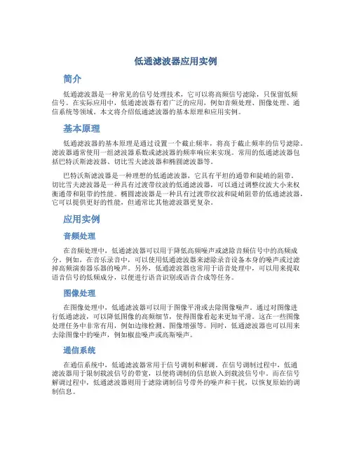
低通滤波器应用实例简介低通滤波器是一种常见的信号处理技术,它可以将高频信号滤除,只保留低频信号。
在实际应用中,低通滤波器有着广泛的应用,例如音频处理、图像处理、通信系统等领域。
本文将介绍低通滤波器的基本原理和应用实例。
基本原理低通滤波器的基本原理是通过设置一个截止频率,将高于截止频率的信号滤除。
滤波器通常使用一组滤波器系数或滤波器的频率响应来实现。
常用的低通滤波器包括巴特沃斯滤波器、切比雪夫滤波器和椭圆滤波器等。
巴特沃斯滤波器是一种理想的低通滤波器,它具有平坦的通带和陡峭的阻带。
切比雪夫滤波器是一种具有过渡带纹波的低通滤波器,可以通过调整纹波大小来权衡通带和阻带的性能。
椭圆滤波器是一种具有过渡带纹波和陡峭阻带的低通滤波器,它可以提供更好的性能,但通常比其他滤波器更复杂。
应用实例音频处理在音频处理中,低通滤波器可以用于降低高频噪声或滤除音频信号中的高频成分。
例如,在音乐录音中,可以使用低通滤波器来滤除录音设备本身的噪声或过滤掉高频演奏器乐器的噪声。
另外,低通滤波器也常用于语音处理中,可以用来提取语音信号的低频成分,以便进行语音识别或语音合成等任务。
图像处理在图像处理中,低通滤波器可以用于图像平滑或去除图像噪声。
通过对图像进行低通滤波,可以降低图像的高频细节,使得图像看起来更加平滑。
这在一些图像处理任务中非常有用,例如边缘检测、图像增强等。
同时,低通滤波器也可以用来去除图像中的噪声,例如椒盐噪声或高斯噪声。
通信系统在通信系统中,低通滤波器常用于信号调制和解调。
在信号调制过程中,低通滤波器用于限制载波信号的带宽,以便将调制的信息嵌入到载波信号中。
而在信号解调过程中,低通滤波器则用于滤除调制信号带外的噪声和干扰,以恢复原始的调制信息。
总结低通滤波器是一种重要的信号处理技术,具有广泛的应用。
本文简要介绍了低通滤波器的基本原理和应用实例,包括音频处理、图像处理和通信系统。
通过合理选择合适的滤波器类型和参数,可以根据实际需求实现信号的滤波和处理。
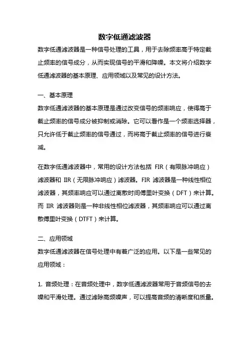
数字低通滤波器数字低通滤波器是一种信号处理的工具,用于去除频率高于特定截止频率的信号成分,从而实现信号的平滑和降噪。
本文将介绍数字低通滤波器的基本原理、应用领域以及常见的设计方法。
一、基本原理数字低通滤波器的基本原理是通过改变信号的频率响应,使得高于截止频率的信号成分被抑制或消除。
它可以看作是一个频率选择器,只允许低于截止频率的信号通过,而将高于截止频率的信号进行衰减。
在数字低通滤波器中,常用的设计方法包括FIR(有限脉冲响应)滤波器和IIR(无限脉冲响应)滤波器。
FIR滤波器是一种线性相位滤波器,其频率响应可以通过离散时间傅里叶变换(DFT)来计算。
而IIR滤波器则是一种非线性相位滤波器,其频率响应可以通过离散傅里叶变换(DTFT)来计算。
二、应用领域数字低通滤波器在信号处理中有着广泛的应用。
以下是一些常见的应用领域:1. 音频处理:在音频处理中,数字低通滤波器常用于音频信号的去噪和平滑处理。
通过滤除高频噪声,可以提高音频的清晰度和质量。
2. 图像处理:在图像处理中,数字低通滤波器常用于图像的平滑处理和边缘检测。
通过去除图像中高频的细节部分,可以使图像更加平滑,并减少噪声的影响。
3. 通信系统:在通信系统中,数字低通滤波器常用于信号的解调和解调。
通过滤除高频噪声和干扰信号,可以提高通信系统的性能和可靠性。
4. 生物医学信号处理:在生物医学领域,数字低通滤波器常用于心电图(ECG)和脑电图(EEG)等生物信号的分析和处理。
通过滤除高频噪声和伪迹,可以提取出有效的生物信号特征。
三、设计方法数字低通滤波器的设计方法有很多种,下面介绍几种常见的设计方法:1. 窗函数法:窗函数法是一种常用的FIR滤波器设计方法。
它通过选择合适的窗函数和滤波器长度,来实现对信号的滤波。
常见的窗函数有矩形窗、汉宁窗和布莱克曼窗等。
2. 巴特沃斯滤波器:巴特沃斯滤波器是一种常用的IIR滤波器设计方法。
它具有平坦的通带和陡峭的阻带特性,可以实现对信号的精确滤波。

低通数字滤波器的主要参数CIC滤波器主要参数插⼊损耗(Insertion Loss):由于滤波器的引⼊对电路中原有信号带来的衰耗。
通带纹波:频响中通带的最⼤幅值和最⼩幅值之间的差值。
正常的纹波⼀般⼩于1db。
不过也视情况⽽⾔,通带纹波会导致通带内的幅值⼤⼩有变化,⼀般要求越⾼,纹波越⼩越好。
通带纹波和滤波器的阶数有关系,阶数越⼤纹波越⼩。
表达式为:-20log10(最⼤幅度)-(-20log10(最⼩幅度) [个⼈感觉通带纹波就是通带衰减ap,但是没找到资料确认]通带容限误差δp :δp ≥ 1/6 * ((pi* fp*M / Fs)^2) M是滤波器的长度 ,fp是通带截⽌频率,Fs是输⼊信号采样率阻带容限误差δs :δs ≥ fs*M/Fs fs是阻带截⽌频率通带衰减 ap(Apass) :20*lg((1+δp) / (1-δp))阻带衰减 as(Astop) :20*lgδs通带截⽌频率 fp :信号在低于通带截⽌频率时,衰减量必须⼩于某个指标——通带纹波阻带截⽌频率 fs :信号在⾼于阻带截⽌频率时,衰减量必须⼤于某个指标——阻带衰减信号滤波后的频谱响应 = 滤波前的频谱 * 滤波器的频率响应在CIC滤波器设计过程中,只要考虑的参数:通带纹波Apass、通带截⽌频率,阻带截⽌频率,阻带衰减接下来,我们看图说话:CIC滤波器:半带滤波器:补偿滤波器:我们⽤fdesign⼯具设计cic补偿滤波器(参考博客:https:///wordwarwordwar/article/details/80561023)1 Fs=1e6;2 hd_cic = cascade(hd1,hd2,hd3,Hb1,Hb2); %%这⾥的dfilt,mfilt对象是⽤fdatool设计导出的,此处省略介绍(见于后续博客) 34 d4 = fdesign.ciccomp(1, ...55,100,800,.0025,100,2000); % design a cic compensator filter6 Hd(4) = design(d4);7 hvt=fvtool(hd_cic,Hd(4),cascade(hd_cic,Hd(4)),'Fs',[Fs Fs/500 Fs], ... % plot whole response8'ShowReference', 'off');910 legend(hvt, 'CIC','CIC compensator', 'Whole response','Location', 'Northeast');d4是补偿滤波器fdesign.ciccomp(滤波器delay,级数,通带截⽌频率,阻带截⽌频率,通带纹波,阻带衰减,当前滤波器输⼊信号的采样率);。
低通滤波器怎么用在信号处理领域,低通滤波器是一种常用的工具,用于去除信号中的高频部分,保留低频成分。
低通滤波器的使用可以帮助我们实现信号去噪、平滑、降采样等多种功能。
在本文中,我们将介绍低通滤波器的类型、工作原理以及如何正确地应用低通滤波器。
低通滤波器类型低通滤波器根据其截止频率的不同可以分为不同类型,常见的有理想低通滤波器、巴特沃斯低通滤波器、切比雪夫低通滤波器等。
每种类型的低通滤波器在频域和时域的特性都不同,选择合适的类型取决于具体的信号处理需求。
低通滤波器工作原理低通滤波器通过设计滤波器的频率响应来实现信号频域的选择性处理。
在频域中,低通滤波器将信号中高于截止频率的部分滤除,保留低频成分。
这样可以去除高频噪声、平滑信号,并且有助于降低信号的采样频率。
低通滤波器应用1.信号去噪:低通滤波器常用于去除信号中的高频噪声,提高信号的清晰度和质量。
2.信号平滑:对于包含较多高频成分的不稳定信号,可以通过低通滤波器平滑信号,使其更易于分析和处理。
3.信号恢复:在某些情况下,信号可能因传输或处理过程中丢失部分频谱信息,可以通过低通滤波器对信号进行恢复。
4.降采样:在需要降低信号采样率的情况下,先使用低通滤波器滤除高频部分,然后再进行下采样操作。
低通滤波器使用注意事项在使用低通滤波器时,需要根据具体情况选择合适的滤波器类型和参数。
需要注意以下几点:1.截止频率选择:截止频率应该根据信号的频率特性来确定,选择过高或过低的截止频率都可能导致滤波效果不佳。
2.滤波器阶数:滤波器的阶数会影响滤波器的性能,通常情况下,阶数越高,滤波器的性能越好,但计算复杂度也会增加。
3.信号延迟:滤波器会引入信号延迟,应根据应用场景考虑延迟对系统性能的影响。
4.实时处理:在实时处理中,需要考虑滤波器的计算效率,避免引入过大的延迟。
综上所述,低通滤波器是信号处理中常用的一种滤波器,可以在去噪、平滑、恢复信号等多个方面起到关键作用。
正确地选择和应用低通滤波器可以提高信号处理的效果和质量,有效地改善系统性能。
低通滤波器低通滤波器的基本电路特点是,只允许低于截止频率的信号通过。
(1)一阶低通Butterworth滤波电路下图a和b是用运算放大器设计的两种一阶Butterworth滤波电路的电路。
图a是反相输入一阶低通滤波器,实际上就是一个积分电路,其分析方法与一阶积分电路相同。
基本滤波电路演示图b是同相输入的一阶低通滤波器。
根据给定的电路图可以得到对滤波器来说,更关心的是正弦稳态是的行为特性,利用拉氏变换与富氏变换的关系,有下图是上式RC=2时的幅频特性和相频特性波特图。
RC=2时一阶Butterworth低通滤波器的频率响应特性(2)二阶低通Butterworth滤波电路下图是用运算放大器设计的二阶低通Butterworth滤波电路。
二阶Butterworth低通滤波电路直接采用频域分析方法得到其中k = 1+R1/R2 。
令Q=1/(3-k),w0=1/RC,则可以写成其中k相当于同相放大器的电压放大倍数,叫做滤波器的通带增益,Q叫做品质因数,w0叫做特征角频率。
下图是二阶低通滤波器在RC=2时的波特图,其中图a是Q>0.707时的效果,图b是Q=0.707时的效果,图c是Q<0.707时的效果。
(a) Q>0.707(b) Q=0.707(c)Q<0.707二阶低通滤波器在RC=2时的波特图从图中可以看出,当Q>0.707 或Q<0.707时,通带边沿处会出现比较大的不平坦现象。
因此,品质因数表明了滤波器通带的状态。
一般要求Q=0.707。
由此可以得到这就是二阶Butterworth滤波器电压增益得计算0.707公式。
令Q=0.707,得0.414R2 = 0.707R1通常把最大增益倍所对应的信号频率叫做截止频率,这时滤波器具有3dB的衰减。
利用滤波器幅频特性的概念,可以得到截止频率w0 =w =1/RC,即f =1/2pRC高通滤波器的特点是,只允许高于截止频率的信号通过。
CASE STYLE: FV1206Generic photo used for illustration purposes onlyPermanent damage may occur if any of these limits are exceeded.1. DC Resistance to ground is 100 Mohms min.2. Measured on Mini-Circuits Characterization T est Board TB-270.ELECTRICAL SPECIFICATIONS 1,2AT 25°CTYPICAL FREQUENCY RESPONSEFUNCTIONAL SCHEMATICREV. BECO-011331LFCN-3800D+RVN220105FEATURESy Excellent power handling, 8W y Small size y 7 sectionsy T emperature stable y L TCC constructiony Protected by U.S Patent 6,943,646APPLICATIONSy Harmonic rejectiony VHF/UHF transmitters/receivers y Lab useOUTLINE DRAWINGDEMO BOARD MCL P/N: TB-270SUGGESTED PCB LAYOUT (PL-137)PRODUCT MARKING: N/AOUTLINE DIMENSIONS(Inches)mmSuggested Layout,Tolerance to be within ±.002A B C D E F G.126.063.037.020.032.009.1693.20 1.600.940.510.810.234.29H J K L M N P wt.087.024.122.024.087.012.071grams2.210.613.100.61 2.210.30 1.80.020TAPE & REEL INFORMATION: F71NOTESA.Performance and quality attributes and conditions not expressly stated in this specification document are intended to be excluded and do not form a part of this specification document.B.Electrical specifications and performance data contained in this specification document are based on Mini-Circuit’s applicable established test performance criteria and measurement instructions.C.The parts covered by this specification document are subject to Mini-Circuits standard limited warranty and terms and conditions (collectively, “Standard T erms”); Purchasers of this part are entitled to the rightsand benefits contained therein. For a full statement of the standard. T erms and the exclusive rights and remedies thereunder, please visit Mini-Circuits’ website at /MCLStore/terms.jspLFCN-3800D+INSERTION LOSS010203040506040008000120001600020000FREQUENCY (MHz)I N S E R T I O N L O S S (d B)LFCN-3800D+VSWR11010040008000120001600020000FREQUENCY (MHz)V S W R。
低通滤波器参数:Fs=8000, fp=2500, fs=3500,Rp=ldB, As = 30dB,其他滤波器可以通过与低通之间的映射关系实现。
號模拟滤波器%巴特沃斯一一滤波器设计wp=2*pi*2500;ws=2*pi*3500;Rp=l;As二30;[N, wc]=buttord(wp, ws, Rp, As,' s')%计算率波器的阶数和3dB 截ll濒率[B,A]=butter(N,wc,'s*) ;%计算滤波器系统函数分子分母务项式fk=0:800/512:8000;wk=2*pi*fk;Hk=freqs (B, A, wk);figureplot(fk/1000, 20*logl0(abs(Hk)));grid on, xlabel C频率(kHz) ' )” ylabel (幅度(dB)')titleC巴特沃斯模拟滤波器')axis (10, 4, -35, 5])巴特沃斯模拟滤波器5-5-10-15-20-25-30[Nl, wpl]=cheblord(wp, ws, Rp, As,' s')%计算切比雪夫滤波器的阶数和通带边' [B1,A1]二chebyl(Nl,Rp,wpl,' s')俺计算滤波器系统函数分子分母等项式 fk=O:800/512:8000;wk=2*pi*fk; Hk=freqs(Bl, Al, wk);figure,plot(fk/1000, 20*logl0(abs(Hk)));grid on, xlabel C 频率(kHz) ) ylabel ('幅度(dB)) title C 切比雪夫I 模拟滤波器') axis (10, 4, -35, 5])切比雪夫橫拟滤液器%切比雪夫II 一一滤波器设计wp 二2*pi*2500;ws=2*pi*3500:Rp 二1;As=30;[N2,wso]=cheb2ord(wp, ws, Rp, As,' s')%计算切比雪夫滤波器的阶数和通带边界频】[B2,A2]=cheby2(Nl,Rp,wso,' s')俺计算滤波器系统函数分子分母形项式fk=0:800/512:8000;wk=2*pi*fk;Hk=freqs (Bl, Al, wk) : figure,plot (fk/1000, 20*logl0(abs(Hk)));grid on, xlabel (* 频率(kHz) 'ylabel ('幅度(dB))titleC 切比雪夫II 模拟滤波器')0 0.5 1 1.5 频率 2 2.5 (kHz) 3 3.5 4%%%切比雪夫I — —滤波器设计wp 二2*pi*2500;ws=2*pi*3500;Rp=l;As 二30;-35axis (10, 4, -35. 5])%%%椭圆一一滤波器设计wp=2*pi*2500;ws=2*pi*3500;Rp=l;As=30;[N, wpo] =ellipord(wp, ws, Rp, As,' s')%讣算滤波器的阶数和通带边界频率 [B,A]=ellip(N,Rp, As.wpo,' s') ;%计算滤波器系统函数分子分母多项式 fk=O:800/512:8000;wk=2*pi*fk; Hk=freqs(Bl, Al, wk):figure,plot(fk/1000, 20*logl0(abs(Hk)));grid on, xlabel C 频率(kHz) 'ylabel ('幅度(dB)')axis(10, 4, -35, 5]), title(,椭圆模拟滤波器')椭回模拟滤液器 50.5 1.5 22.5 33.6硕率(kHz) •30切比雪天II 模拟滤波器0-511520■■2QDP) am%%%数字滤波器%脉冲响应法滤波器设讣fp=2500;fs=3500;Fs=8000;wp=2*fp/Fs;ws=2*fs/Fs;%求归一化数字通带截止频率,求归一化数字阻带起始频率del taw=ws-wp; %求过渡带宽N0=ceil(6. 6/deltaw) 求窗口长度N=NO+mod(NO+l> 2); %确保窗「I长度N为奇数n=N-l;%求出滤波器的阶数nwn=(ws+wp)/2; $求滤波器的截止频率b=firl(n,wn)%利用firl函数求出滤波器的系数[Hk,w] = freqz(b, 1); % 计算频率响应mag = abs (Hk) ; %求幅频特性db = 20*logl0(mag/max(mag)) ; % 化为分〔丿!值dw 二pi/512; %关F pi 归一化Rp = - (min(db(l:wp*pi/dw+l))) % 检验通带波动As = - (max (db (ws*pi/dw+l: 512))) % 检验最小口1 带哀减figure, plot(0:pi/511:pi, db), grid onaxis([0, 4. 0, -80, 5]), title('数字滤波器-------- 脉冲响应法')%%%firl窗函数法fp二2500;fs=3500;Fs二8000;rs=30;wp=2*fp*pi/Fs: ws=2*f s*pi/Fs; %求归一化数j:通带截止频率,求归一化数字阻带起始频率Bt=ws - wp; %求过渡带宽alpha=0. 5842*(rs-21)^0. 4+0. 07886*(rs-21);%计算kaiser 窗的控制参数M=ceil ((rs-8),/2. 285/Bt);%求出滤波器的阶数wc= (ws+wp)/2/pi;玄求逍波器的截止频上于pi归一化hk=firl (M, wc, kaiser (M+l, alpha))$利用firl函数求出滤波器的系数EHk, w] = freqz (hk, 1) ;% 计算频率响应mag = abs (Hk) ; %求幅频特性db = 20*logl0(mag/max(mag)) ; % 化为分贝值dbl二db‘ ;figure, plot(0:pi/511:pi, dbl),grid onaxis([0, 4. 0, -80, 5]), titleC 数字滤波器-------- firl W函数法')%频率采样法fp二2500;fs=3500;Fs二8000;rs=30;wp=2*fp*pi/Fs: ws=2*f s*pi/Fs; %求归一化数j:通带截止频率,求归一化数字阻带起始频率Bt=ws - wp; %求过渡带宽m=l;alpha=0. 5842*(rs-21) ^0. 4+0. 07886* (rs-21) ;%计算kaiser 窗的控制参数N=ceil(mTl)*2*pi/Bt;%求出滤波器的阶数N=N+mod(N+l,2);Np=fix(wp/(2*pi/N));Ns=N-2*Np-l;Hk=[ones(l, Np+1), zeros (1, Ns), ones(l, Np)];wc= (ws+wp)/2/pi;玄求滤波器的截止频率并关于pi归一化hk=firl (M, wc, kaiser(M+l, alpha))%利用firl函数求出滤波器的系数[Hk, w]二freqz (hk, 1);% 讣算频率响应mag = abs (Hk) ; %求幅频特性db = 20*logl0(mag/max(mag)) ; % 化为分〔丿!值dbl二db‘ ;figure, plot(0:pi/511:pi, dbl),grid onaxis([0, 4. 0,-80, 5]), titleC数字滤波器--------- 频率采样法')%利用等波纹最佳逼近法设计FIR数字滤波器Fs二8000;f二[2500, 3500]rp=l;rs=30;deltal=(10^ (rp/20)-l)/(10* (rp/20)+l) ;delta2=107-rs/20);rip=.deltal, delta2];[M, fo, mo, w]=remezord(f, m, rip, Fs);%边界频率为模拟频率时必须加入采样频率M=M+1;%估算的M直达不到要求,家1后满足要求hn=remez (M, fo, mo, w);EHk,w] = freqz(hn, 1); % 计算频率响应mag = abs (Hk) ; %求幅频特性db = 20*logl0(mag/max(mag)) ; % 化为分贝值dbl二db‘ ;figure, plot(0:pi/511:pi, dbl),grid onaxis([0, 4・0, -80, 5]), titleC数字滤波器一一等波纹最佳逼近法')希望对大家有所帮助.多谢您的浏览! (注:可编辑下载,若有不当之处, 请指正,谢谢!)。
The University of South China数字信号处理课程设计说明书学院名称指导教师班级学号学生姓名2010年6 月设计一个按因子I=5的内插器,要求镜像滤波器通带最大衰减为0.1dB ,阻带最小衰减为30dB ,过渡带宽不大于20/π,设计FIR 滤波器系数h(n)一、初始设计(1) 幅度指标 可以两种方式给出。
第一种,叫做绝对指标,它提出了对幅度回应函数|H (jw)| 的要求。
这些指标一般可直接用于FIR 滤波器。
第二种方法叫做相对指标,它以分贝(dB )值的形式提出要求,其定义为:0|)(||)(|log 20max10≥-=jwjw e H e H dB 经过定义中所包含的归一化,所有滤波器的相对幅频特性最高处的值为0dB ,由于定义式中有一个负号,幅频特性小的地方,其dB 值反而是正的。
绝对指标:[0,wp]段叫通带,δ1是在理想通带中能接受的振幅波动或(容限) [ws, ]段叫做阻带,δ2是阻带中能接受的振幅波动或(容限)[wp,ws]叫做过渡带,在此段上幅度回应通常没有限制,也可以给些弱限制。
低通滤波器的典型幅度指标 相对指标(dB ):p R 是通带波动的dB 值;s A 是阻带衰减的dB 值。
由于绝对指标中的)1(|)(|1max δ+=jw H ,因此 011log 201110>+--=δδp R , )(ωj e G cω1 1+ p 1-ps p s11log 201210>>+-=δδs A 逆向的关系为 20201101101ppR R --+-=δ2020121010)1(s s A A --≈+=δδ(2)低通FIR 滤波器阶数的估计 πωωδδ2/)(6.1413)lg(20p s s p N ---≈(3)滤波器结构分析: 整数倍内插器的FIR 直接实现整数I 倍内插是在已知的相邻两个原采样点之间等间隔插入I-1个新的采样值。
对已知的采样序列)(11T n x 进行D/A 转移,得道原来的模拟信号)(t x a ,然后再对)(t x a 进行较高采样率的采样得到)(22T n y ,这里 21IT T = I 为大于1的整数,称为内插因子。
整数倍内插是先在已知采样序列)(11T n x 的相邻两个样点之间等间隔插入I-1个0值点,然后进行低通滤波器,即可获得I 倍内插的结果。
内插方案如图所示:)(11T n x )(22T n v )(22T n y图中↑ I 表示在)(11T n x 相邻样点之间插入I-1个0值采样,称为零值内插器。
)(11T n x 、)(22T n y 的傅里叶变换为:)(1jw e X 、)(2jw e Y ,二者均为周期函数,若二者都用模拟频率Ω表示,则(1jw e X =)(1T j e X Ω,周期为11/2T sa π=Ω;)(2jw e Y =)(2T i e Y Ω,周期为2sa Ω=112)//(2/2sa I I T T Ω==ππ。
)(22T n v =⎪⎩⎪⎨⎧±±=其它当02,,0n)(212I I I T n x↑ I )(22T n h)(22T n v 的傅里叶变换)(2jw e V 为)(2jw eV ==∑∞-∞=-222)(22n n jw e T n v )(1T j e X Ω=)(1jw e X 要想从)(2jw eV 得到)(2jw e Y ,就必须滤除这些镜像频谱。
所以,要求滤波器)(22T n h 的理想低通幅频特性如图所示。
实际工作中,c sa Ω>Ω21所以允许)(2jw e H 有一定的过渡带,可 用线性相位FIR 滤波器实现。
根据其功能,将)(22T n h 称为镜像滤波器。
|)(|2T j e H Ω2/1sa Ω- 0 2/1sa Ω 1sa Ω ΩI /π- 0 I /ππ 2π 镜像滤波器的理想幅频特性将理想镜像滤波器的阻带截止频率换算成数字频率为II T T T sa ππ==Ω11212 所以,理解情况下,镜像滤波器)(22T n h 的频率响应特性为)(2jw e H ⎪⎩⎪⎨⎧≤≤<≤πππ||I 0|w |0 22w I C 式中,C 为定标系数,因此输出频谱为⎪⎩⎪⎨⎧≤≤<≤πππ|| 0|w |0 )()(2222w I I e CX e Y jIw jw 而后得出:定标系数C=I 。
内插器的输入、输出关系 )()()(222222mT Tn h mT v T n y m -=∑∞-∞=频域输入、输出关系 )()()(222jw jw jw e H e V eY =)()()(z H z X z Y '=镜像滤波器)(22T n h 采用FIR 结构时,I 倍内插器的FIR 直接实现结构如图所示:)(11T n x )(22T n w h (0) )(22T n y12-z )(2T h12-z ])2[(2T N h - 12-z ])1[(2T N h -按整数因子I 内插系统的直接型FIR 滤波结构当满足线性相位条件[)(22T n h =))1((22T n N h --]时,可用线性相位结构实现,将乘法次数再减少一半。
取N=9,画出内插旗的线性相位FIR 直接高效实现结构,如图所示:)(11T n x h(0))(22T n y 12-z )(2T h 12-z12-z )2(2T h 12-z12-z )3(2T h 12-z12-z )4(2T h 12-z内插器的线性相位FIR 直接实现结构 ↑ I↑ I ↑ I↑ I↑ I↑ I ↑ I↑ I ↑ I ↑ I多相滤波器结构按整数因子I 内插系统的高效FIR 滤波器结构可以用一组较短的多相滤波器组实现。
如果FIR 滤波器总长度为M=NI ,则多相滤波器组由I 个长度为N=M/I 的短滤波器构成。
且I 个短滤波器轮流分时工作。
从m=0开始,整数因子I 内插系统的输出序列y(m)计算如下: ∑-==-=1)(*)()()()(N n kkn x n p n j x n p m y式中,m=jI+k;k=0,1,2,....,I-1;j=0,1,2,....。
显然,当m=jI+k 从0开始增大时,k 从0开始以I 为周期循环取值;j 表示循环周期数。
所以,实现式中的多相滤波器结构如下图所示。
I 个子滤波器均运行于低采样率x F 下,且系数少,计算量小,所以多相滤波器结构是一种高效结构。
输入端的x(n)每移入一个样值,I 个子滤波器分别计算出y(m)的I 个样值,选择电子开关以高采样率x F =I x F ,依次逆时针循环选取I 个子滤波器的输出,形成输出序列y(m)。
实现了整数因子I 内插功能。
x(n) 速率=I x F y(m)采样速率x y IF F =采样率x F 采样率x F整数因子I 内插系统的多相滤波器结构二、目标设计一个按因子I=5的内插器,要求镜像滤波器通带最大衰减为0.1dB ,阻带最小衰减为30dB ,过渡带宽不大于20/π,设计FIR 滤波器系数h(n))(1n p)(2n p )(1n p I -)(0n p1、低通FIR 滤波器技术指标 采样频率s F =8000Hz20/3π=p w (通带截止频率) 5/π=s w (阻带截止频率)pa =0.1dB (通带最大衰减)s a =30dB (阻带最小衰减)过渡带宽度 πωωω05.0=-=∆p s2、Remezord 函数的调用[n, fo, mo, w] = remezord([600 800], [1 0], [0.057 0.15], 8000); b = remez(n, fo, mo, w); %[h w] = freqz(b, 1, 128); %plot(w/pi, abs(h)); freqz(b, 1, 128);求得h(n)长度M=47,为了满足5的整数倍,取M=50,调用rezem 函数求得h(n)如下:h(0)=6.684246e-002=h(49) h(1)=-3.073256e-002=h(48)h(2)=-4.303671e-002=h(47) h(3)=-5.80309-002=h(46) h(4)=-6.759203e-002=h(45) h(5)=-6.493009e-002=h(44) h(6)=-4.657608e-002=h(43) h(7)=-1.386252-002=h(42) h(8)=2.674276e-002=h(41) h(9)=6.463158e-002=h(40) h(10)=8.776083e-002=h(39) h(11)=8.607556e-002=h(38) h(12)=5.500303e-002=h(37) h(13)=-1.800562e-003=h(36) h(14)=-7.220485e-002=h(35) h(15)=-1.370181e-001=h(34) h(16)=-1.740193e-001=h(33) h(17)=-1.631924e-001=h(32) h(18)=-9.215300e-002=h(31) h(19)=4.004513e-002=h(30) h(20)=2.202029e-001=h(29) h(21)=4.239994e-001=h(28) h(22)=6.191918e-001=h(27) h(23)=7.725483e-001=h(26) h(24)=8.68808e-001=h(25)多相滤波器实现结构中的五个多相滤波器系数如下:)}45(),40(),35(),30(),25(),20(),15(),10(),5(),0({)()(0h h h h h h h h h h nI h n p ==)}50(),45(),40(),35(),30(),25(),20(),15(),10(),5({)5()()}49(),44(),39(),34(),29(),24(),19(),14(),9(),4({)4()()}48(),43(),38(),33(),28(),23(),18(),13(),8(),3({)3()()}47(),42(),37(),32(),27(),22(),17(),12(),7(),2({)2()()}46(),41(),36(),31(),26(),21(),16(),11(),6(),1({)1()(54321h h h h h h h h h h nI h n p h h h h h h h h h h nI h n p h h h h h h h h h h nI h n p h h h h h h h h h h nI h n p h h h h h h h h h h nI h n p =+==+==+==+==+=从五个自滤波器的频响特性可以解释“多相滤波器”含义。