3. Filter Functions
- 格式:pdf
- 大小:203.33 KB
- 文档页数:25

jsfilter函数JSFilter函数是一个JavaScript函数库,其主要功能是对用户输入的数据进行过滤和验证。
该函数库可以用于各种Web应用程序,包括表单验证、文件上传、数据库查询等。
JSFilter函数库包含了多个函数,每个函数都有不同的功能。
其中一些常用的函数包括:1. isEmail(email):验证一个字符串是否为合法的电子邮件地址。
2. isInt(number):验证一个字符串是否为整数。
3. isFloat(number):验证一个字符串是否为浮点数。
4. isDate(date):验证一个字符串是否为合法的日期格式。
5. isAlpha(string):验证一个字符串是否只包含字母。
6. isAlphanumeric(string):验证一个字符串是否只包含字母和数字。
7. stripTags(string):从一个字符串中去除HTML标签。
8. trim(string):去除字符串两端的空格。
9. escapeHTML(string):将HTML标签转义为实体字符。
10. unescapeHTML(string):将实体字符转义回HTML标签。
使用JSFilter函数库非常简单。
只需要在需要使用它的页面中引入jsfilter.js文件,并调用相应的函数即可。
例如,如果要验证用户输入的电子邮件地址是否合法,可以使用以下代码:if(!isEmail(email)){alert("请输入合法的电子邮件地址!");return false;}此外,JSFilter还支持自定义规则。
例如,如果要检查用户输入的密码是否符合特定规则(例如必须包含至少一个大写字母和一个数字),可以使用以下代码:var password = document.getElementById("password").value; if(!JSFilter.validate(password, [{rule: /[A-Z]/, message: "密码必须包含至少一个大写字母!"}, {rule: /\d/, message: "密码必须包含至少一个数字!"}])){alert("请输入符合规则的密码!");return false;}总之,JSFilter函数库是一个非常实用的工具,可以帮助开发人员轻松地验证和过滤用户输入的数据。

filter函数的用法用通配符-回复题目:filter函数的用法与通配符引言:在Python编程中,处理数据集合时,经常需要根据特定条件筛选出满足条件的元素。
此时,filter函数就能够派上用场。
filter函数是Python内置的一个高阶函数,用于筛选序列中的元素,返回满足条件的元素组成的迭代器。
同时,结合通配符的灵活应用能够更加方便地实现特定条件的筛选。
本文将会详细介绍filter函数的基本用法以及结合通配符的使用方法,并通过实例逐步解释。
一、filter函数的基本用法filter函数的语法如下:filter(function, iterable)其中,function是一个判断函数,用于对iterable中的每个元素进行条件判断。
iterable是一个序列,可以是列表、元组、集合、字典等。
1.1 无通配符的示例首先,让我们从一个简单的示例开始:pythonnumbers = [1, 2, 3, 4, 5, 6, 7, 8, 9, 10]def is_even(x):return x 2 == 0result = filter(is_even, numbers)even_numbers = list(result)print(even_numbers)上述代码中,numbers是一个包含1到10的列表。
我们定义了一个is_even函数,用于判断一个数字是否为偶数。
然后,我们使用filter函数将is_even函数作为条件判断函数,对numbers中的每个元素进行筛选,返回满足条件(即为偶数)的元素,并通过list()函数将结果转换为列表。
最后,将满足条件的偶数列表打印出来。
输出结果为:[2, 4, 6, 8, 10],符合预期。
1.2 结合通配符的示例接下来,我们将通过一个例子,展示filter函数与通配符的结合应用。
假设我们有一个字符串列表,包含了一些文件名,我们需要找出所有以“.txt”结尾的文件名。

python filter函数的用法介绍Python内置的filter()函数能够从可迭代对象(如字典、列表)中筛选某些元素,并生成一个新的迭代器。
可迭代对象是一个可以被“遍历”的Python对象,也就是说,它将按顺序返回各元素,这样我们就可以在for循环中使用它。
filter()函数的基本语法是:filter(function, iterable)返回一个可迭代的filter对象,可以使用list()函数将其转化为列表,这个列表包含过滤器对象中返回的所有的项。
filter()函数所提供的过滤方法,通常比用列表解析更有效,特别是当我们处理更大的数据集时。
例如,列表解析会生成一个新列表,这会增加该处理的运行时间。
当列表解析执行完毕它的表达式后,内存中会有两个列表。
但是,filter()将生成一个简单的对象,该对象包含对原始列表的引用、提供的函数以及原始列表中位置的索引,这样操作占用的内存更少。
下面介绍filter()的四种不同用法:在filter()中使用特殊函数filter()的第一个参数是一个函数,用它来决定第二个参数所引用的可迭代对象中的每一项的去留。
此函数被调用后,当返回False时,第二个参数中的可迭代对象里面相应的值就会被删除。
针对这个函数,可以是一个普通函数,也可以使用lambda函数,特别是当表达式不那么复杂的时候。
下面是filter()中使用lambda函数的方法:filter(lambda item: item[] expression, iterable)将下面的列表,用于lambda函数,根据lambda函数表达式筛选列表中的元素。
creature_names = ['Sammy', 'Ashley', 'Jo', 'Olly','Jackie', 'Charlie']要筛选此列表以元音开头的水族馆生物的名称,lambda函数如下:print(list(filter(lambda x: x[0].lower() in 'aeiou', creature_names)))在这里,我们将列表中的一个项声明为x,并以x[0]的方式访问每个字符串的第一个字符,并且要将字母转化为小写,以确保将字母与'aeiou'中的字符匹配。
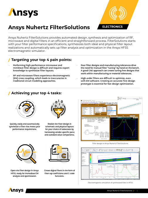
Ansys Nuhertz FilterSolutions Ansys Nuhertz FilterSolutions provides automated design, synthesis and optimization of RF, microwave and digital filters in an efficient and straightforward process. FilterSolutions starts with your filter performance specifications, synthesizes both ideal and physical filter layout realizations and automatically sets up filter analysis and optimization in the Ansys HFSS electromagnetic simulator.•Performing high-performance microwave and mmWave filter design is difficult and requires expertknowledge to synthesize filter layouts.•RF and microwave filters experience electromagnetic (EM) cross coupling, which leads to inaccuracies intraditional circuit modeling approaches. •Poor filter designs and manufacturing tolerances drivethe need for manual filter “tuning” by hand on the bench. A good CAE approach can create tuning free designs that work within manufacturing or material tolerances.•High-order filters are difficult to optimize, even with EM software. Creating an accurate first designprototype is essential for fast design optimization.Open the filter design in AnsysHFSS, ready for immediate EManalysis and optimization.Create digital filters in the form of filter tap coefficients and C-codefunctions./Targeting your top 4 pain points:/Achieving your top 4 tasks:Quickly, easily and automaticallysynthesize a filter that meets yourperformance requirement.Realize the filter design in schematic and physical layouts for your choice of substrates byharnessing vendor-specific partsand standard value components.Filter design in Ansys Nuhertz FilterSolutionsElectromagnetic simulation of synthesized filter in HFSS/W hat differentiates Ansys Nuhertz FilterSolutions? •Performance specification for Layout-to-EM-Optimization in a single smooth workflow•Ability to evaluate the widest range of filter topologies (Bessel, Butterworth, Chebyshev I and II, Elliptic, Gaussian, Delay, Hourglass, Legendre, Matched, Raised Cosine, Tubular, Zigzag, Coupled-Resonator and Cross-Coupled Folded Resonator)•Highly accurate distributed filter layout synthesis based on EM-derived model discontinuities and couplings•Integrates with HFSS for gold-standard EM analysis accuracy and for EM-based optimization•Ability to synthesize filter topologies for analog and digital filter topologies; a single tool for creating accurate filters for both analog and digital signal processing (DSP) applications•Planar filter realizations in the widest available media classes (microstrip, stripline, asymmetric stripline, suspended substrate)/Ansys Nuhertz FilterSolutions provides automatic filter design for: •Lumped filters , presenting synthesized filter schematics that fulfill the filter performance specification. Also provides values for filters realized on PCBs with surface mount or thru-hole discrete components.•Distributed (transmission line filters) - High-performance distributed filters manufactured on microwave or mmWave substrates. These filters are usually realized with transmission lines, open or shorted stubs, vias, coupled lines and cross-coupled transmission line systems. A broad class of microwave and mmWave filters can be realized through precision patterning of conductors on one to three planar substrates.•Digital filters realized in software for digital signal processing (DSP) systems or on microcontrollers. These are software programs, applied to digital signal processing operating on data from digital sampling systems.•Zero-inductor analog filters - Popular at lower frequencies (audio and mid-frequency analog systems), these filters can be realized on PCB process technology with OpAmps in an analog filter format.•IC-based filters in the form of non-programmable digital filters can also be implemented in IC processes utilizing MOSFETS and capacitors to occupy minimum real estate and utilize a switched-capacitor approach.LUMPED (PASSIVE) FILTER MODULE Synthesizes a lumped component filter (single or double-termination) of a selected filter topology to realize user-specified performance characteristics. Standard value components may be applied, with standard (or non-standard) tolerance values for Monte-Carlo analysis. Components have ideal or finite Q or may be based upon vendor component library models.CAPABILITIESDISTRIBUTED FILTER MODULE The Distributed Filter module synthesizes filter layouts on physics-accurate materials, incorporating transmission lines and hybrid lumped elements. Filter layouts can be realized in a variety of substrate formats, including microstrip, suspended substrate and stripline. Physical layouts (including metallization and substrate material properties) can be realized quickly and accurately. Filter layouts are fully parameterized and may be opened in HFSS for immediate EM analysis; all geometries, materials, ports and analysis setups are automatically created. HFSS designs are fully parameterized and optimization setups are provided, so the designer can proceed directly to design optimization to desired response goals.ACTIVE FILTER MODULE Some filter designs call for elimination of inductors and active filter designs with OpAmps can sometimes provide an attractive alternative. The FilterSolutions Active Filter module synthesizes filters to meet user-specified performance requirements in a wide range of filter topologies, such as Thomas, Akerberg-Mossberg, Sallen-Key, Multiple Feedback, Leapfrog, GICs and more. Incorporate OpAmp models from your favorite vendor and include finite Q and gain effects in your active filter designs.SWITCHED-CAPACITOR FILTER MODULEAnother zero-inductor realization: Switched capacitor filters are generally realized in semiconductor processes where capacitors and switching transistors occupy comparatively small spaces. Switched-capacitor filters may be used to realize digital filters and involve sampling circuit topologies. The Switched-Capacitor Filter module synthesizes designs in IIR and FIR realizations, as well as Bilinear, Matched-Z, Step Invariant, Modified Impulse Invariant and custom Z-transform designs.ANSYS, Inc. *******************866.267.9724© 2021 ANSYS, Inc. All Rights Reserved.DISTRIBUTED FILTER DESIGN TOPOLOGIES Lumped Translation, Inductor Translation, Stepped Impedance, Shunt Stub Resonators, Open Stub Resonators, Spaced Stubs, Dual Resonators, Spaced Dual Resonators, Parallel Edge Coupled, Hairpin, Miniature Hairpin, Ring Resonator, Interdigital, ComblineACTIVE FILTER IMPLEMENTATIONS Thomas 1 and 2, Sallen & Key, Parallel, Akerberg, Multiple Feedback (MFB), GIC Biquad, GIC Ladder, Leap FrogDIGITAL FILTER DESIGNS BASED ON THE FOLLOWING DIGITAL TRANSFORMATIONSBilinear, Impulse Invariant (IIR), Matched Z, Step Invariant, FIR Approximation. FIR Filter Types: Rectangular, Bartlett, Hanning, Hamming, Blackman, Blackman-Harris, Kaiser, Dolph-Cheby, Remez, Raised Cosine, Root Raised Cosine, Cosine Filter, Sine Filter, Matched Filter, DelayFilter DIGITAL FILTER MODULE For DSP and sampled systems, FilterSolutions takes user-specified performance specifications and a desired topology and synthesizes filter coefficients to realize the digital filter. Digital transformations are provided to Bilinear, Impulse Invariant, Step Invariant, Matched-Z and Finite Impulse Response (FIR) approximation. Filter realizations are provided in the form of the discrete transfer function, filter tap/block coefficients or as C-code ready for incorporation into a DSP code block.ZMATCH MODULE Zmatch starts with complex load definitions and synthesizes a matching network for maximum power transfer. Includes both Discrete Frequency and Broadband Match modes. Optimal matching networks are provided in lumped, distributed and hybrid realizations.FILTER TYPES AVAILABLE (LUMPED AND DISTRIBUTED FILTERS)Gaussian, Bessel, Butterworth, Legendre, Chebyshev (I and II), Hourglass, Elliptic, Raised Cosine, Matched, Delay FILTER CLASSES AVAILABLE (LUMPED AND DISTRIBUTED FILTERS)Lumped Translation, Inductor Translation, Stepped Impedance, Shunt Stub Resonators, Open Stub Resonators, Spaced Stubs, Dual Resonators, Spaced Dual Resonators, Parallel Edge Coupled, Hairpin, Miniature Hairpin, Ring Resonator, Interdigital, Combline。

filter函数的用法详解:多条件中的特定函数1. 定义filter函数是Python内置的一个高阶函数,用于对可迭代对象(例如列表、元组、字典、集合等)中的元素进行过滤,并返回满足特定条件的元素。
filter函数的定义如下:filter(function, iterable)其中,function是一个函数,用于对可迭代对象的每个元素进行判断,返回True或False;iterable是一个可迭代对象,可以是列表、元组、字典、集合等。
2. 用途filter函数主要用于对可迭代对象进行筛选,过滤出满足特定条件的元素,从而得到一个新的可迭代对象。
它可以简化代码,提高代码的可读性和可维护性。
filter函数常用于以下场景:•过滤出满足特定条件的元素,例如筛选出大于某个阈值的数字、筛选出包含特定字符的字符串等。
•过滤出满足多个条件的元素,例如同时满足某个范围和某个条件的数字。
•过滤出满足函数返回值为True的元素,例如根据某个函数的返回值来筛选元素。
3. 工作方式filter函数的工作方式如下:•对于可迭代对象中的每个元素,依次调用function函数,并将元素作为参数传入。
•如果function函数的返回值为True,则将该元素保留下来;如果返回值为False,则将该元素过滤掉。
•最后,将所有保留下来的元素组成一个新的可迭代对象,并返回。
示例代码如下:# 过滤出大于5的数字numbers = [1, 2, 3, 4, 5, 6, 7, 8, 9]result = filter(lambda x: x > 5, numbers)print(list(result)) # 输出 [6, 7, 8, 9]在上述示例中,lambda函数lambda x: x > 5用于判断数字是否大于5,filter函数根据这个lambda函数的返回值来过滤出大于5的数字。
4. 多条件中的特定函数在实际应用中,我们经常需要对可迭代对象进行多条件的筛选。

filter用法js -回复Filter是JavaScript数组中的一个高阶函数,它可以按照指定的条件筛选出符合条件的元素,生成一个新的数组。
本文将介绍filter函数的基本用法、参数、返回值以及实际应用等内容,帮助读者逐步理解该函数的使用方式。
# 1. filter函数的基本用法在JavaScript中,我们可以用以下方式来调用filter函数:array.filter(callback(element[, index[, array]])[, thisArg])其中,array是要进行筛选的原始数组,callback是一个用来测试数组中每个元素的函数,thisArg是可选的参数,用于指定callback函数中的this 值。
# 2. 参数说明2.1 callbackcallback是一个用来测试数组中每个元素的函数。
它接收三个参数:element表示当前正在被测试的元素,index表示当前元素在数组中的索引,array表示正在被遍历的数组。
2.2 thisArgthisArg是一个可选参数,用于指定callback函数中的this值。
如果省略该参数,则默认为undefined。
# 3. 返回值filter函数返回一个新的数组,由所有通过callback测试的元素组成。
如果某个元素通过测试,则将其添加到新数组中。
# 4. 实际应用4.1 筛选奇数假设我们有一个数字数组,我们想要筛选出其中的奇数。
我们可以使用filter函数来实现:javascriptlet numbers = [1, 2, 3, 4, 5, 6];let oddNumbers = numbers.filter(function(element) {return element 2 !== 0;});console.log(oddNumbers); [1, 3, 5]在这个例子中,我们定义了一个匿名函数,它的作用是判断当前元素是否为奇数。
The simulation and the realization of the digital filterWith the information age and the advent of the digital world, digital signal processing has become one of today's most important disciplines and door technology. Digital signal processing in communications, voice, images, automatic control, radar, military, aerospace, medical and household appliances, and many other fields widely applied. In the digital signal processing applications, the digital filter is important and has been widely applied.1、figures Unit on :Analog and digital filtersIn signal processing, the function of a filter is to remove unwanted parts of the signal, such as random noise, or to extract useful parts of the signal, such as the components lying within a certain frequency range.The following block diagram illustrates the basic idea.There are two main kinds of filter, analog and digital. They are quite different in their physical makeup and in how they work. An analog filter uses analog electronic circuits made up from components such as resistors, capacitors and op amps to produce the required filtering effect. Such filter circuits are widely used in such applications as noise reduction, video signal enhancement, graphic equalisers in hi-fi systems, and many other areas. There are well-established standard techniques for designing an analog filter circuit for a given requirement. At all stages, the signal being filtered is an electrical voltage or current which is the direct analogue of the physical quantity (e.g. a sound or video signal or transducer output) involved. A digital filter uses a digital processor to perform numerical calculations on sampled values of the signal. The processor may be a general-purpose computer such as a PC, or a specialised DSP (Digital Signal Processor) chip. The analog input signal must first be sampled and digitised using an ADC (analog to digital converter). The resulting binary numbers, representing successive sampled values of the input signal, are transferred to the processor, which carries out numerical calculations on them. These calculations typically involve multiplying the input values by constants and adding the products together. If necessary, theresults of these calculations, which now represent sampled values of the filtered signal, are output through a DAC (digital to analog converter) to convert the signal back to analog form.Note that in a digital filter, the signal is represented by a sequence of numbers, rather than a voltage or current.The following diagram shows the basic setup of such a system.Unit refers to the input signals used to filter hardware or software. If the filter input, output signals are separated, they are bound to respond to the impact of the Unit is separated, such as digital filters filter definition. Digital filter function, which was to import sequences X transformation into export operations through a series Y.According to figures filter function 24-hour live response characteristics, digital filters can be divided into two, namely, unlimited long live long live the corresponding IIR filter and the limited response to FIR filters. IIR filters have the advantage of the digital filter design can use simulation results, and simulation filter design of a large number of tables may facilitate simple. It is the shortcomings of the nonlinear phase; Linear phase if required, will use the entire network phase-correction. Image processing and transmission of data collection is required with linear phase filters identity. And FIR linear phase digital filter to achieve, but an arbitrary margin characteristics. Impact from the digital filter response of the units can be divided into two broad categories : the impact of the limited response (FIR) filters, and unlimited number of shocks to (IIR) digital filters.FIR filters can be strictly linear phase, but because the system FIR filter function extremity fixed at the original point, it can only use the higher number of bands to achieve their highselectivity for the same filter design indicators FIR filter called band than a few high-IIR 5-10 times, the cost is higher, Signal delay is also larger. But if the same linear phase, IIR filters must be network-wide calibration phase, the same section also increase the number of filters and network complexity. FIR filters can be used to achieve non-Digui way, not in a limited precision of a shock, and into the homes and quantitative factors of uncertainty arising from the impact of errors than IIR filter small number, and FIR filter can be used FFT algorithms, the computational speed. But unlike IIR filter can filter through the simulation results, there is no ready-made formula FIR filter must use computer-aided design software (such as MATLAB) to calculate. So, a broader application of FIR filters, and IIR filters are not very strict requirements on occasions.Unit from sub-functions can be divided into the following four categories :(1) Low-filter (LPF);(2) high-filter (HPF);(3) belt-filter (BPF);(4) to prevent filter (BSF).The following chart dotted line for the ideals of the filter frequency characteristics :A1(f) A2(f)10 f2cf 0 f2cf(a) (b)A3(f) A4(f)0 f1cf2cf 0 f1cf2cf(c) (d)(a)LPF (b)HPF (c)BPF (d)BSF2、MATLAB introducedMATLAB is a matrix laboratory (Matrix Laboratory) is intended. In addition to an excellent value calculation capability, it also provides professional symbols terms, word processing, visualization modeling, simulation and real-time control functions. MATLAB as the world's top mathematical software applications, with a strong engineering computing, algorithms research, engineering drawings, applications development, data analysis and dynamic simulation, and other functions, in aerospace, mechanical manufacturing and construction fields playing an increasingly important role. And the C language function rich, the use of flexibility, high-efficiency goals procedures. High language both advantages as well as low level language features. Therefore, C language is the most widely used programming language. Although MATLAB is a complete, fully functional programming environment, but in some cases, data and procedures with the external environment of the world is very necessary and useful. Filter design using Matlab, could be adjusted with the design requirements and filter characteristics of the parameters, visual simple, greatly reducing the workload for the filter design optimization.In the electricity system protection and secondary computer control, many signal processing and analysis are based on are certain types Yeroskipou and the second harmonics of the system voltage and current signals (especially at D process), are mixed with a variety of complex components, the filter has been installed power system during the critical components. Current computer protection and the introduction of two digital signal processing software main filter. Digital filter design using traditional cumbersome formula, the need to change the parameters after recalculation, especially in high filters, filter design workload. Uses MATLAB signal processing boxes can achieve rapid and effective digital filter design and simulation.MATLAB is the basic unit of data matrix, with its directives Biaodashi mathematics, engineering, commonly used form is very similar, it is used to solve a problem than in MATLAB C, Fortran and other languages End precision much the same thing. The popular MATLAB 5.3/Simulink3.0 including hundreds of internal function with the main pack and 30 types of tool kits (Toolbox). kits can be divided into functional tool kits and disciplines toolkit. MATLAB tool kit used to expand the functional symbols terms, visualization simulationmodelling, word processing and real-time control functions. professional disciplines toolkit is a stronger tool kits, tool kits control, signal processing tool kit, tool kits, etc. belonging to such communicationsMATLAB users to open widely welcomed. In addition to the internal function, all the packages MATLAB tool kits are readable document and the document could be amended, modified or users through Yuanchengxu the construction of new procedures to prepare themselves for kits.3、Digital filter designDigital filter design of the basic requirementsDigital filter design must go through three steps :(1) Identification of indicators : In the design of a filter, there must be some indicators. These indicators should be determined on the basis of the application. In many practical applications, digital filters are often used to achieve the frequency operation. Therefore, indicators in the form of general jurisdiction given frequency range and phase response. Margins key indicators given in two ways. The first is absolute indicators. It provides a function to respond to the demands of the general application of FIR filter design. The second indicator is the relative indicators. Its value in the form of answers to decibels. In engineering practice, the most popular of such indicators. For phase response indicators forms, usually in the hope that the system with a linear phase frequency bands human. Using linear phase filter design with the following response to the indicators strengths:①it only contains a few algorithms, no plural operations;②there is delay distortion, only a fixed amount of delay; ③the filter length N (number of bands for N-1), the volume calculation for N/2 magnitude.(2) Model approach : Once identified indicators can use a previous study of the basic principles and relationships, a filter model to be closer to the target system.(3) Achieved : the results of the above two filters, usually by differential equations, system function or pulse response to describe. According to this description of hardware or software used to achieve it.4、Introduced FPGAProgrammable logic device is a generic logic can use a variety of chips, which is to achieve ASIC ASIC (Application Specific Integrated Circuit) semi-customized device, Its emergenceand development of electronic systems designers use CAD tools to design their own laboratory in the ASIC device. Especially FPGA (Field Programmable Gate Array) generated and development, as a microprocessor, memory, the figures for electronic system design and set a new industry standard (that is based on standard product sales catalogue in the market to buy). Is a digital system for microprocessors, memories, FPGA or three standard building blocks constitute their integration direction.Digital circuit design using FPGA devices, can not only simplify the design process and can reduce the size and cost of the entire system, increasing system reliability. They do not need to spend the traditional sense a lot of time and effort required to create integrated circuits, to avoid the investment risk and become the fastest-growing industries of electronic devices group. Digital circuit design system FPGA devices using the following main advantages(1)Design flexibleUse FPGA devices may not in the standard series device logic functional limitations. And changes in system design and the use of logic in any one stage of the process, and only through the use of re-programming the FPGA device can be completed, the system design provides for great flexibility.(2) Increased functional densityFunctional density in a given space refers to the number of functional integration logic. Programmable logic chip components doors several high, a FPGA can replace several films, film scores or even hundreds of small-scale digital IC chip illustrated in the film. FPGA devices using the chip to use digital systems in small numbers, thus reducing the number of chips used to reduce the number of printed size and printed, and will ultimately lead to a reduction in the overall size of the system.(3) Improve reliabilityPrinting plates and reduce the number of chips, not only can reduce system size, but it greatly enhanced system reliability. A higher degree of integration than systems in many low-standard integration components for the design of the same system, with much higher reliability. FPGA device used to reduce the number of chips required to achieve the system in the number printed on the cord and joints are reduced, the reliability of the system can be improved.(4) Shortening the design cycleAs FPGA devices and the programmable flexibility, use it to design a system for longer than traditional methods greatly shortened. FPGA device master degrees high, use printed circuit layout wiring simple. At the same time, success in the prototype design, the development of advanced tools, a high degree of automation, their logic is very simple changes quickly. Therefore, the use of FPGA devices can significantly shorten the design cycle system, and speed up the pace of product into the market, improving product competitiveness.(5) Work fastFPGA/CPLD devices work fast, generally can reach several original Hertz, far larger than the DSP device. At the same time, the use of FPGA devices, the system needed to achieve circuitclasses and small, and thus the pace of work of the entire system will be improved.(6) Increased system performance confidentialityMany FPGA devices have encryption functions in the system widely used FPGA devices can effectively prevent illegal copying products were others(7) To reduce costsFPGA device used to achieve digital system design, if only device itself into the price, sometimes you would not know it advantages, but there are many factors affecting the cost of the system, taken together, the cost advantages of using FPGA is obvious. First, the use of FPGA devices designed to facilitate change, shorten design cycles, reduce development costs for system development; Secondly, the size and FPGA devices allow automation needs plug-ins, reducing the manufacturing system to lower costs; Again, the use of FPGA devices can enhance system reliability, reduced maintenance workload, thereby lowering the cost of maintenance services for the system. In short, the use of FPGA devices for system design to save costs.FPGA design principles :FPGA design an important guiding principles : the balance and size and speed of exchange, the principles behind the design of the filter expression of a large number of certification.Here, "area" means a design exertion FPGA/CPLD logic resources of the FPGA can be used to the typical consumption (FF) and the search table (IUT) to measure more general measure can be used to design logic equivalence occupied by the door is measured. "pace" means stability operations in the chip design can achieve the highest frequency, the frequency of the time series design situation, and design to meet the clock cycle -- PADto pad, Clock SetupTime, Clock Hold Beijing, Clock-to-Output Delay, and other characteristics of many time series closely related. Area (area) and speed (speed) runs through the two targets FPGA design always is the ultimate design quality evaluation criteria. On the size and speed of the two basic concepts : balance of size and speed and size and speed of swap.One pair of size and speed is the unity of opposites contradictions body. Requirements for the design of a design while the smallest, highest frequency of operation is unrealistic. More scientific goal should be to meet the design requirements of the design time series (includes requirements for the design frequency) premise, the smallest chip area occupied. Or in the specified area, the design time series cushion greater frequency run higher. This fully embodies the goals of both size and speed balanced thinking. On the size and speed requirements should not be simply interpreted as raising the level and design engineers perfect sexual pursuit, and should recognize that they are products and the quality and cost of direct relevance. If time series cushion larger design, running relatively high frequency, that the design Jianzhuangxing stronger, more quality assurance system as a whole; On the other hand, the smaller size of consumption design is meant to achieve in chip unit more functional modules, the chip needs fewer, the entire system has been significantly reduced cost. As a contradiction of the two components, the size and speed is not the same status. In contrast, meet the timetables and work is more important for some frequency when both conflicts, the use of priority guidelines.Area and the exchange rate is an important FPGA design ideas. Theoretically, if a design time series cushion larger, can run much higher than the frequency design requirements, then we can through the use of functional modules to reduce the consumption of the entire chip design area, which is used for space savings advantages of speed; Conversely, if the design of a time series demanding, less than ordinary methods of design frequency then generally flow through the string and data conversion, parallel reproduction of operational module, designed to take on the whole "string and conversion" and operate in the export module to chip in the data "and string conversion" from the macro point of view the whole chip meets the requirements of processing speed, which is equivalent to the area of reproduction - rate increase.For example. Assuming that the digital signal processing system is 350Mb/s input data flow rate, and in FPGA design, data processing modules for maximum processing speed of 150Mb/s, because the data throughput processing module failed to meet requirements, it is impossible to achieve directly in the FPGA. Such circumstances, they should use"area-velocity" thinking, at least three processing modules from the first data sets will be imported and converted, and then use these three modules parallel processing of data distribution, then the results "and string conversion," we have complete data rate requirements. We look at both ends of the processing modules, data rate is 350Mb/s, and in view of the internal FPGA, each sub-module handles the data rate is 150Mb/s, in fact, all the data throughput is dependent on three security modules parallel processing subsidiary completed, that is used by more chip area achieve high-speed processing through "the area of reproduction for processing speed enhancement" and achieved design.FPGA is the English abbreviation Field of Programmable Gate Array for the site programmable gate array, which is in Pal, Gal, Epld, programmable device basis to further develop the product. It is as ASIC (ASIC) in the field of a semi-customized circuit and the emergence of both a customized solution to the shortage circuit, but overcome the original programmable devices doors circuit few limited shortcomings.FPGA logic module array adopted home (Logic Cell Array), a new concept of internal logic modules may include CLB (Configurable Logic Block), export import module IOB (Input Output Block) and internal links (Interconnect) 3. FPGA basic features are :(1) Using FPGA ASIC design ASIC using FPGA circuits, the chip can be used,while users do not need to vote films production.(2) FPGA do other customized or semi-customized ASIC circuits throughout the Chinese specimen films.3) FPGA internal capability and rich I/O Yinjue.4) FPGA is the ASIC design cycle, the shortest circuit, the lowest development costs, risks among the smallest device5) FPGA using high-speed Chmos crafts, low consumption, with CMOS, TTL low-power compatibleIt can be said that the FPGA chip is for small-scale systems to improve system integration, reliability one of the bestCurrently FPGA many varieties, the Revenue software series, TI companies TPC series, the fiex ALTERA company seriesFPGA is stored in films from the internal RAM procedures for the establishment of the state of its work, therefore, need to programmed the internal Ram. Depending on the differentconfiguration, users can use a different programming methodsPlus electricity, FPGA, EPROM chips will be read into the film, programming RAM中data, configuration is completed, FPGA into working order. Diaodian, FPGA resume into white films, the internal logic of relations disappear, FPGA to repeated use. FPGA's programming is dedicated FPGA programming tool, using generic EPROM, prom programming device can. When the need to modify functional FPGA, EPROM can only change is. Thus, with a FPGA, different programming data to produce different circuit functions. Therefore, the use of FPGA very flexible.There are a variety of FPGA model : the main model for a parallel FPGA plus a EPROM manner; From the model can support a number of films FPGA; serial prom programming model could be used serial prom FPGA programming FPGA; The external model can be engineered as microprocessors from its programming microprocessors.Verilog HDL is a hardware description language for the algorithm level, doors at the level of abstract level to switch-level digital system design modelling. Modelling of the target figure by the complexity of the system can be something simple doors and integrity of electronic digital systems. Digital system to the levels described, and in the same manner described in Hin-time series modelling.Verilog HDL language with the following description of capacity : design behaviour characteristics, design data flow characteristics, composition and structure designed to control and contain the transmission and waveform design a certification mechanism. All this with the use of a modelling language. In addition, Verilog HDL language programming language interface provided by the interface in simulation, design certification from the external design of the visit, including specific simulation control and operation.Verilog HDL language grammar is not only a definition, but the definition of each grammar structure are clear simulation, simulation exercises. Therefore, the use of such language to use Verilog simulation models prepared by a certification. From the C programming language, the language inherited multiple operating sites and structures. Verilog HDL provides modelling capacity expansion, many of the initial expansion would be difficult to understand. However, the core subsets of Verilog HDL language very easy to learn and use, which is sufficient for most modelling applications. Of course, the integrity of the hardware description language is the most complex chips from the integrity of the electronic systems described.historyVerilog HDL language initially in 1983 by Gateway Design Automation companies for product development simulator hardware modelling language. Then it is only a dedicated language. Since their simulation, simulation devices widely used products, Verilog HDL as a user-friendly and practical language for many designers gradually accepted. In an effort to increase the popularity of the language activities, Verilog HDL language in 1990 was a public area. Open Verilog International (OVI) is to promote the development of Verilog international organizations. 1992, decided to promote OVI OVI standards as IEEE Verilog standards. The effort will ultimately succeed, a IEEE1995 Verilog language standard, known as IEEE Std 1364-1995. Integrity standards in Verilog hardware description language reference manual contains a detailed description.Main capacity:Listed below are the main Verilog hardware description language ability*Basic logic gate, and, for example, or have embedded in the language and nand* Users of the original definition of the term (UDP), the flexibility. Users can be defined in the original language combinations logic original language, the original language of logic could also be time series* Switches class infrastructure models, such as the nmos and pmos also be embedded in the language* Hin-language structure designated for the cost of printing the design and trails Shi Shi and design time series checks.* Available three different ways to design or mixed mode modelling. These methods include : acts described ways - use process of structural modelling; Data flow approach - use of a modelling approach Fuzhi expression; Structured way - using examples of words to describe modular doors and modelling.* Verilog HDL has two types of data : data types and sequence data line network types. Line network types that the physical links between components and sequence types that abstract data storage components.* To describe the level design, the structure can be used to describe any level module example * Design size can be arbitrary; Language is design size (size) impose any restrictions* Verilog HDL is no longer the exclusive language of certain companies but IEEE standards.* And the machine can read Verilog language, it may as EDA tools and languages of the world between the designers* Verilog HDL language to describe capacity through the use of programming language interface (PLI) mechanism further expansion. PLI is to allow external functions of the visit Verilog module information, allowing designers and simulator world Licheng assembly* Design to be described at a number of levels, from the switch level, doors level, register transfer level (RTL) to the algorithm level, including the level of process and content* To use embedded switching level of the original language in class switch design integrity modelling* Same language can be used to generate simulated incentive and certification by the designated testing conditions, such as the value of imports of the designated*Verilog HDL simulation to monitor the implementation of certification, the certification process of implementing the simulation can be designed to monitor and demonstrate value. These values can be used to compare with the expectations that are not matched in the case of print news reports.* Acts described in the class, not only in the RTL level Verilog HDL design description, and to describe their level architecture design algorithm level behavioural description* Examples can use doors and modular structure of language in a class structure described* Verilog HDL mixed mode modelling capabilities in the design of a different design in each module can level modelling* Verilog HDL has built-in logic function, such as*Structure of high-level programming languages, such as conditions of expression, and the cycle of expression language, language can be used* To it and can display regular modelling* Provide a powerful document literacy* Language in the specific circumstances of non-certainty that in the simulator, different models can produce different results; For example, describing events in the standard sequence of events is not defined.5、In troduction of DSPToday, DSP is w idely used in the modern techno logy and it has been the key part of many p roducts and p layed more and mo re impo rtant ro le in our daily life.Recent ly, Northw esternPo lytechnica lUniversity Aviation Microelect ronic Center has comp leted the design of digital signal signal p rocesso r co re NDSP25, w h ich is aim ing at TM S320C25 digital signal p rocesso r of Texas Inst rument TM S320 series. By using top 2dow n design flow , NDSP25 is compat ible w ith inst ruct ion and interface t im ing of TM S320C25.Digital signal processors (DSP) is a fit for real-time digital signal processing for high-speed dedicated processors, the main variety used for real-time digital signal processing to achieve rapid algorithms. In today's digital age background, the DSP has become the communications, computer, and consumer electronics products, and other fields based device.Digital signal processors and digital signal processing is inseparably, we usually say "DSP" can also mean the digital signal processing (Digital Signal Processing), is that in this digital signal processors Lane. Digital signal processing is a cover many disciplines applied to many areas and disciplines, refers to the use of computers or specialized processing equipment, the signals in digital form for the collection, conversion, recovery, valuation, enhancement, compression, identification, processing, the signals are compliant form. Digital signal processors for digital signal processing devices, it is accompanied by a digital signal processing to produce. DSP development process is broadly divided into three phases : the 20th century to the 1970s theory that the 1980s and 1990s for the development of products. Before the emergence of the digital signal processing in the DSP can only rely on microprocessors (MPU) to complete. However, the advantage of lower high-speed real-time processing can not meet the requirements. Therefore, until the 1970s, a talent made based DSP theory and algorithms. With LSI technology development in 1982 was the first recipient of the world gave birth to the DSP chip. Years later, the second generation based on CMOS工艺DSP chips have emerged. The late 1980s, the advent of the third generation of DSP chips. DSP is the fastest-growing 1990s, there have been four successive five-generation and the generation DSP devices. After 20 years of development, the application of DSP products has been extended to people's learning, work and all aspects of life and gradually become electronics products determinants.。
filter函数的用法多条件摘要:一、filter函数简介二、filter函数的语法1.参数详解2.举例说明三、多条件过滤实例1.实例一:筛选大于等于18岁的用户2.实例二:筛选薪资在5000到10000之间的员工四、总结与拓展正文:一、filter函数简介filter函数是Python内置的高阶函数,用于过滤序列。
它可以接收一个函数和一个序列作为参数,将序列中满足函数条件的元素筛选出来,返回一个新的可迭代对象。
二、filter函数的语法1.参数详解- 函数:用于筛选序列中的元素,该函数需要接收一个参数并返回一个布尔值。
- 序列:待筛选的序列对象,可以是列表、元组、集合等。
2.举例说明假设我们有一个用户列表,包含年龄和薪资两个属性,我们可以使用filter函数筛选出满足条件的用户。
```pythonusers = [{"age": 16, "salary": 4000},{"age": 18, "salary": 6000},{"age": 20, "salary": 8000},{"age": 22, "salary": 10000},]# 筛选年龄大于等于18岁的用户age_geq_18 = list(filter(lambda x: x["age"] >= 18, users))print(age_geq_18)# 筛选薪资在5000到10000之间的员工salary_between_5000_and_10000 = list(filter(lambda x: 5000 <= x["salary"] <= 10000, users))print(salary_between_5000_and_10000)```三、多条件过滤实例1.实例一:筛选大于等于18岁的用户在上面的用户列表示例中,我们已经演示了如何使用filter函数筛选大于等于18岁的用户。
MATLAB中filter函数的用法1. 介绍在MATLAB中,filter函数是一个用于数字滤波的重要工具。
它可以对信号进行滤波处理,去除噪声、平滑数据或者突出特定频率的成分。
filter函数的使用非常灵活,可以根据不同的需求选择不同的滤波器类型和参数。
2. 基本语法filter函数的基本语法如下:y = filter(b, a, x)其中,b和a是滤波器的系数,x是待滤波的信号,y是滤波后的结果。
3. 滤波器系数滤波器系数是滤波器的关键参数,决定了滤波器的特性。
在MATLAB中,可以通过多种方式获取滤波器系数,例如使用fir1函数生成FIR滤波器系数,使用butter 函数生成巴特沃斯滤波器系数等。
以FIR滤波器为例,使用fir1函数生成滤波器系数的代码如下:order = 10; % 滤波器阶数cutoff = 0.5; % 截止频率b = fir1(order, cutoff);在上述代码中,order表示滤波器的阶数,cutoff表示截止频率。
fir1函数将根据给定的阶数和截止频率生成对应的滤波器系数。
4. 滤波器类型MATLAB中的filter函数支持多种滤波器类型,常用的包括低通滤波器、高通滤波器、带通滤波器和带阻滤波器等。
4.1 低通滤波器低通滤波器用于去除高频成分,保留低频成分。
在MATLAB中,可以使用fir1函数生成低通滤波器系数,并将其作为参数传递给filter函数。
order = 10; % 滤波器阶数cutoff = 0.5; % 截止频率b = fir1(order, cutoff, 'low');y = filter(b, 1, x);在上述代码中,’low’表示生成低通滤波器系数。
4.2 高通滤波器高通滤波器用于去除低频成分,保留高频成分。
在MATLAB中,可以使用fir1函数生成高通滤波器系数,并将其作为参数传递给filter函数。
order = 10; % 滤波器阶数cutoff = 0.5; % 截止频率b = fir1(order, cutoff, 'high');y = filter(b, 1, x);在上述代码中,’high’表示生成高通滤波器系数。
filter函数的三个参数filter函数是在Python中非常常用的函数之一,它可以用于过滤一个序列中的元素。
它的基本语法是:filter(function, iterable),其中function是一个函数,iterable是一个可迭代对象。
filter函数会遍历iterable中的每个元素,并将其传递给function中进行判断,如果function返回True,则该元素被保留下来,否则被过滤掉。
除了这两个常见的参数外,filter函数还有一个可选的参数:key。
key参数是一个函数,它会被应用到iterable中的每个元素上,用于返回一个用于排序的关键字。
在这篇文章中,我们将详细介绍filter函数的三个参数。
一、function参数function参数是filter函数中最重要的参数之一,它决定了过滤条件。
function参数可以是一个普通的函数,也可以是一个lambda 表达式。
在使用function参数时,需要注意以下几点:1. function函数必须返回一个布尔值,即True或False。
2. function函数接受一个参数,即iterable中的每个元素。
3. function函数可以是一个普通的函数,也可以是一个lambda 表达式。
下面是一个使用普通函数作为function参数的例子:```pythondef is_even(n):return n % 2 == 0numbers = [1, 2, 3, 4, 5, 6, 7, 8, 9, 10]result = filter(is_even, numbers)print(list(result)) # [2, 4, 6, 8, 10]```在这个例子中,我们定义了一个函数is_even,它的作用是判断一个数是否为偶数。
我们将这个函数作为function参数传递给filter函数,用于过滤一个列表中的偶数。
下面是一个使用lambda表达式作为function参数的例子:```pythonnumbers = [1, 2, 3, 4, 5, 6, 7, 8, 9, 10]result = filter(lambda x: x % 2 == 0, numbers)print(list(result)) # [2, 4, 6, 8, 10]```在这个例子中,我们使用lambda表达式定义了一个函数,它的作用和is_even函数相同。
Chapter3Filter FunctionsIn the last chapter expressions for phase and log-amplitude variances were de-rived.These expressions contained an aperturefilter function.In this chapter explicitfilter functions are derived for many cases of interest.First,those needed to calculate variances of any Zernike mode on an unobscured circular aperture are found.Next,expressions tofind piston and tilt on an annular aperture are derived.Filter functions required to determine the effect of either afinite-size source or receiver on the scintillation are derived.Thefilter function to be used when both the receiver and source arefinite in size is also given.Often in adaptive-optics systems the phase produced by a focused beam of finite size is used to correct an outgoing collimated beam.The source of the focused beam may not be coaxial with the outgoing beam.Filter functions that apply for each of these cases are derived.Allfilter functions are given assuming the wave is collimated and infinite in extent.Thesefilter functions can be applied to focused orfinite beams by changing the transverse coordinate toγtimes the transverse coordinate,where γis the propagation parameter defined in eq.2.74for a source at z=0,and in eq.2.77for a source at z=L.Newfilter functions can be created from existing complexfilter functions by taking the absolute value squared of their difference.This technique is used to find thefilter function that applies to the performance of an adaptive-optics system.This technique is used mainly in the next chapter.Filter functions derived in this chapter are for circular apertures,which are the most commonly encountered.Filter functions for other shapes can be derived with similar methods.Generally,one can use thefilter functions for the variance.For some problems that have several effects present,one is required to start with the expressions for phase and log-amplitude and apply thefilter functions before the variance is found.The method and two examples illustrating it are given at the end of the chapter.To evaluate various integrals,I shall need some Bessel function relations.The recurrence relations for Bessel functions are703Filter Functionsd[r p J p(ar)]dr=ar p J p−1(ar),and(3.1)d drJ p(ar)r p=−ar pJ p+1(ar).(3.2)Two important special cases ared[rJ1(ar)]dr=ar J0(ar),and(3.3)ddr[J0(ar)]=−a J1(ar).(3.4) I also use the following integrals where n is an integerJ n(r)=i−n2π2πdϕcos(nϕ)exp[i r cos(ϕ)]=12π2πdϕcos[r cos(ϕ)+nϕ],(3.5)and2πdϕsin(nϕ)exp[i r cos(ϕ)]=0.(3.6) 3.1Circular Aperture ModesOne often is interested in obtaining weighted averages of the phase or log-amplitude over a receive aperture.The weights typically are polynomials,nor-mally referred to as“modes”.Commonly,the receive aperture is an unobscured circle or an annulus.In this section unobscured apertures are considered.Filter functions for an annulus are found in a similar fashion in the next section.Modes are defined for a Gaussian beam in the next chapter.Consider the Zernike modes that were defined in a very useful way by Noll (1976).His expressions are for an aperture of unit diameter,and they are mod-ified here to apply to an aperture of diameter D.The definition of the x and y components of the Zernike polynomials areZ m,n(ρ,θ)x=√n+1R mn(2ρ/D)√2cos(mθ),and(3.7)Z m,n(ρ,θ)y=√R mn(2ρ/D)√2sin(mθ),(3.8)for m=0.For m=0one usesZ0,n(ρ,θ)=√n+1R0n(2ρ/D).(3.9)The radial function is given byR mn (2ρ/D)=(n−m)/2q=0(−1)qq!(n−q)!(2ρ/D)n−2q[(n+m)/2−q]![(n−m)/2−q]!.(3.10)3.1Circular Aperture Modes71 There are requirements that m≤n,and that n−m be even.These polynomials are of interest because they correspond to the commonoptical aberrations.Z0,0(ρ,θ)is piston,Z1,1(ρ,θ)x and Z1,1(ρ,θ)yare the twocomponents of tilt,Z0,2(ρ,θ)is focus,and Z2,2(ρ,θ)x and Z2,2(ρ,θ)yare the twocomponents of astigmatism,Z1,3(ρ,θ)x and Z1,3(ρ,θ)yare the two componentsof coma,and Z0,4(ρ,θ)is third-order spherical distortion.Of particular interest are the modes for pistonZ0,0(ρ,θ)=1,(3.11)and tiltZ1,1(ρ,θ)x=4ρDcos(θ),(3.12)Z1,1(ρ,θ)y=4ρDsin(θ).(3.13)These modes are orthonormal.The normalization of the Zernike modes waschosen so that4πD2dρZ2n,m(ρ,θ)W(ρ)=1.(3.14)The aperture function W(ρ),defined in eq.2.150,is equal to unity inside the aperture and zero outside.Expressed in terms of the unit step,it isW(ρ)=U(D/2−|ρ|).(3.15) The Fourier transforms of Zernike polynomials defined by using eq.2.99G(κ)=4πD2dρW(ρ)Z m,n(ρ,θ)exp(iκ·ρ),(3.16)are equal toG m,n(κ)x G m,n(κ)y G0,n(κ)⎫⎪⎬⎪⎭=√2Jn+1(κD/2)κD/2⎧⎪⎨⎪⎩(−1)(n−m)/2i n√2cos(mϕ),(−1)(n−m)/2i n√2sin(mϕ),(−1)n/2(m=0).(3.17)These are the complexfilter functions for extracting Zernike modes.Note that the direction of the Zernike mode is in the direction ofκ.The absolute value squared of these,referred to simply asfilter functions,areF m,n(κ)x F m,n(κ)y F0,n(κ)⎫⎪⎬⎪⎭=(n+1)2J n+1(κD/2)κD/22⎧⎪⎨⎪⎩2cos2(mϕ),2sin2(mϕ),1(m=0).(3.18)Piston and tiltfilter functions are of particular interest.Two representations of thesefilter functions are given.For different problems,one or the other rep-resentation is appropriate.For piston,thefirst representation gives thefilter function that extracts phase variance due to piston.In the second represen-tation,thefilter function extracts variance of the stroke of aflat mirror that723Filter Functionsproduces this piston by reflection.For tilt,thefirstfilter function extracts phase variance due to tilt,and the second extracts the variance of the corresponding angular displacement in real space.The condition n=m=0gives the piston phase-variancefilter functionF(κ)=2J1(κD/2)κD/22.(3.19)To obtain the representation that extracts the mean-square piston stroke,the filter function has to be divided by the wavenumber squared.Thefilter function tofind piston stroke variance is thusF(κ)= 1k02 2J1(κD/2)κD/22.(3.20)Thisfilter function can be used to calculate effects such as aperture averaging of scintillation,which affects the twinkling of stars and planets,because piston is basically a simple aperture average.The terms n=m=1gives thefilter function to determine tilt phase varianceF x(κ) F y(κ) F(κ)⎫⎪⎬⎪⎭=4J2(κD/2)κD/22⎧⎪⎨⎪⎩cos2(ϕ),sin2(ϕ),1.(3.21)The three terms are the x,y,and total tilt phase variance.Thefilter function for variance of tilt angle in real space is a factor of(4/k0D)2 times the phase-variancefilter function.Thefilter function to determine tilt anglevariance isF x(κ)F y(κ)F(κ)⎫⎪⎬⎪⎭=16k0D2 J2(κD/2)κD/22⎧⎪⎨⎪⎩cos2(ϕ),sin2(ϕ),1.(3.22)The local orfinal diameter must be inserted in k0D depending on the problem.Often one wants the average phase variance on an aperture with some Zernike modes removed.This will be found byfirst calculating the phase variance at any point in the aperture,which is needed for some problems such as those concerning the structure function,and then averaging this expression over the aperture.3.1Circular Aperture Modes73Consider the case where the phase is multiplied by afilter function G(κ)that arises from anisoplanatism.From the definition above G n,m(γκ)is either purely real or imaginary.For this caseˆF (γκ)=|G(κ)|2exp(iγκ·ρ)−n,mG n,m(γκ)Z n,m(ρ,θ)2=F(κ)1−2cos(γκ·ρ)n,mRe G n,m(γκ)Z n,m(ρ,θ)−2sin(γκ·ρ)n,mIm G n,m(γκ)Z n,m(ρ,θ)+n,mo,pG n,m(γκ)G∗o,p(γκ)Z n,m(ρ,θ)Z o,p(ρ,θ).(3.23)This is thefilter function that multiplies the phase expression to obtain phase with some Zernike modes removed if the phase is not averaged over the aperture. When the integration inκspace is performed,the cross product terms with different values of m integrate to zero.However,for the same m the cross product terms do not integrate to zero,which is the indication that the Zernike modes are not statistically independent.The mode function for piston and tilt are given,since they are the most important.For pistonG0,0(γκ)Z0,0(ρ)=2J1(γκD/2)γκD/2.(3.24)For the x component of tiltG1,1(γκ)x Z1,1(ρ,θ)x=i16J2(γκD/2)γκD/2(ρ/D)cos(θ)cos(ϕ),(3.25)and for the y component of tiltG1,1(γκ)y Z1,1(ρ,θ)y=i16J2(γκD/2)γκD/2(ρ/D)sin(θ)sin(ϕ).(3.26)As a reminder,θis the angle in real space andϕis the angle inκspace.For the total tiltG1,1(γκ)Z1,1(ρ,θ)=i 16J2(γκD/2)γκD/2ρDcos(θ−ϕ)=i16J2(γκD/2)γκD/2ρ·κDκ.(3.27)Thefilter function to remove piston when there is no aperture averaging isF(γκ)=1−2cos(γκ·ρ)2J1(γκD/2)γκD/2+2J1(γκD/2)γκD/22.(3.28)Thefilter function to remove tilt when there is no aperture averaging is743Filter FunctionsF(γκ)=1−32cos(θ−ϕ)cos(γκ·ρ)ρJ2(γκD/2)γκD2/2+16ρJ1(γκD/2)γκD/2cos(θ−ϕ)2.(3.29)Let us nowfind the aperture-averaged phase variance with some Zernike modes removed.In that case one needs to integrate thefilter function over the entire aperture of area A to obtainˆF(γκ)=dρˆF (γκ)A=F (γκ)1−n,mF n,m(γκ),(3.30)where eq.2.99and the orthonomality of the Zernike modes on the aperture were used.The phase variance that results from thisfilter function is the total phase variance minus the variance of each of the Zernike modes that are to be removed. For instance,thefilter function tofind the aperture-averaged variance with piston removed isF(γκ)=⎡⎣1−0,0n,m=0F n,m(γκ)⎤⎦=1−2J1(γκD/2)γκD/22.(3.31)For piston and tilt removal thefilter function isF(γκ)=1−2J1(γκD/2)γκD/22−4J2(γκD/2)γκD/22.(3.32)One cannot use these last two equations in calculating the structure function with some Zernike modes removed because for the structure function the modes are not integrated over the aperture.One approach is to use an orthogonal decomposition into Karhunen-Lo`e ve polynomials which are statistically inde-pendent.The lowest order Karhunen-Lo`e ve polynomials are close in shape to the Zernike polynomials.Wang and Markey(1978)show that assuming Zernike modes are statistically independent results in errors of as much as10%.Rather than doing that,we willfind an expression for the structure function with some Zernike modes removed.The structure function isDφ(αD,ρ)= [φ(ρ)−φ(αD+ρ)]2 .(3.33) Let A(ρ)represent the sum of Zernike modes that need to be removedA(ρ)=n,mG n,m(γκ)Z n,m(ρ,θ).(3.34)3.2Piston and Tilt on an Annulus75Let the phase without the Zernike modes removed be f(ρ)Dφ(αD,ρ)= [f(ρ)−A(ρ)−f(ρ+αD)+A(ρ+αD)]2= [f(ρ)−f(ρ+αD)]2 − [A(ρ)−A(ρ+αD)]2+2 {f(ρ)−A(ρ)−[f(ρ+αD)−A(ρ+αD)]}[A(ρ+αD)−A(ρ)] .(3.35)We need to calculate these three terms to obtain the structure function.Often we want to remove tilt,and for this case use eq.3.27to obtain[A(ρ)−A(ρ+αD)]2=7.190 γDr05/3α2.(3.36)Let us now give thefilter function for another type of tilt.The Zernike com-ponent of tilt is also referred to as Z-tilt.Some tilt sensors respond to this quantity,while others respond to the centroid position of the focused aperture distribution,a quantity that is closer to gradient tilt.The definition of G-tiltphase isG-tilt=4πD2dρ∇tΦ(ρ),(3.37)where the integration is over the circular aperture and∇t is the transverse gradient.G-tilt,in a geometric sense,is equal to the average ray direction, corresponding to the average phase gradient over the aperture.One can calculate this in transform space by multiplying the piston component of phase by iκ/k0. Thefilter function tofind gradient-tilt angle variance is thusF x(κ) F y(κ) F(κ)⎫⎪⎬⎪⎭=4k0D2J21(κD/2)⎧⎪⎨⎪⎩cos2(ϕ),sin2(ϕ),1.(3.38)Thefilter function to calculate phase variance of G-tilt is obtained by using the same arguments as before.Thefilter function tofind the phase variance due to gradient tilt is thusF x(κ) F y(κ) F(κ)⎫⎪⎬⎪⎭=J21(κD/2)⎧⎪⎨⎪⎩cos2(ϕ),sin2(ϕ).1.(3.39)3.2Piston and Tilt on an AnnulusAs with afilled-in circular aperture,the complexfilter function for Zernike tilt on an annulus is the Fourier transform of the aperture function for tilt.For tilt in the x-direction,thefilter function isG x(κ)=dρg x(ρ)exp(iκ·ρ)=adρx exp(iκ·ρ),(3.40)763Filter Functionswhere a is a normalizing factor,and the integration is over an annulus with inner diameter D i and outer diameter D.Note that g x(ρ)=ax.The angular and radial integrations can be performed with eq.3.5and eq.3.1to giveG x(κ)=πa cos(ϕ)4D3J2(κD/2)κD/2−D3iJ2(κD i/2)κD i/2,(3.41)whereϕis the angle inκspace.To get the correct constant assume that a pure x-tilt is applied,i.e.,let the phase beφ(ρ)=b x.The tilt angle in real space is b/k0.Therefore,b/k0=dρg x(ρ)ϕ(ρ)=a bdρx2=πa b(D4−D4i)64.This gives a=64/πk0(D4−D4i).Thefilter function is the absolute magnitude squared of the complexfilter function.Thefilter function tofind the x-component of Zernike-tilt angle vari-ance on an annulus is given byF x(κ)=16/k0D1−(D i/D)42J2(κD/2)κD/2−DiD3J2(κD i/2)κD i/22cos2(ϕ).(3.42)The complexfilter function for the x-component of gradient tilt on an annular aperture can be found in exactly the same way to obtainG x(κ)=11−(D i/D)2J1(κD/2)κD/2−2J1(κD i/2)κD i/2iκk0cos(ϕ).(3.43)Thefilter function of G-tilt angle in the x-direction isF x(κ)=4/k0D1−(D i/D)2}2J1(κD/2)−D iDJ1(κD i/2)2cos2(ϕ).(3.44)The y component of tilt has the cosine replaced by a sine.The total tilt has the cosine replaced by unity.Thefilter function for tilt variance is obtained from thefilter function for tilt. Given the tilt T on an annulus,the phase variance(now referring to averaging over the aperture)due to this tilt,which can be arbitrarily taken to be in the x direction,isσ2 T =1Adρ(k0T·ρ)2=k2T2AD/2D i/2dρρ32πdθcos2(θ)=T2k216D2+D2i.Therefore,thefilter function for total tilt phase variance on an annulus is3.2Piston and Tilt on an Annulus 77F (κ)= 161+(D i /D )2 J 2(κD/2)κD/2− D i D 3J 2(κD i /2)κD i /2 2.(3.45)As before,one obtains the x (y )component by multiplying this expression by cos 2(ϕ) sin 2(ϕ) .The piston filter functions can be found in the same manner.The Zernike piston on an annulus is the Fourier transform of the aperture function,i.e.,G s (κ)=ad ρexp (i κ·ρ),where a is a normalizing factor,and the integration is over the annulus.The angular and radial integrations can be performed with eq.3.5and eq.3.3to giveG (κ)=πa [D J 1(κD/2)−D i J 1(κD i /2)].(3.46)To get the normalizing constant a assume that a pure piston is applied,i.e.,let the phase be φ(ρ)=b.The piston in mirror stroke is b/k 0,sob/k 0=a bd ρ=πa b D 2−D 2i /4.Therefore,a =4/πk 0(D 2−D 2i ).The complex filter function isG (κ)=2k 0 1−(D i /D ) J 1(κD/2)κD/2− D i D 2J 1(κD i /2)κD i /2 .(3.47)The filter function is the absolute magnitude squared of the complex filter func-tion.The filter function for piston stroke variance on an annulus is given byF (κ)=⎧⎨⎩2k 0 1−(D i /D ) ⎫⎬⎭2 J 1(κD/2)κD/2− D i D 2J 1(κD i /2)κD i /2 2.(3.48)Given the piston P on the aperture,the average phase variance due to piston isσ2P =1Ad ρ(k 0P )2=k 20P 2,where A is the aperture area.Therefore,one finds the filter function to obtainthe piston phase variance by multiplying the filter function for the piston by k 20.The filter function for piston phase variance on an annulus is given byF (κ)= 21−(D i /D )2 2 J 1(κD/2)κD/2− D i D 2J 1(κD i /2)κD i /2 2.(3.49)783Filter Functions3.3Finite Apertures and Focal AnisoplanatismI derivefilter functions for two types of problems that are analyzable in a similar fashion.The analysis is a generalization of the two-wave problem considered in Chap.2.Here the source is allowed to befinite in size.Thefirst type offilter function is for either a distributed source or afinite-size receive aperture that produces phase and scintillation levels in a receiver that can be very different from those of a point source or point receiver.For instance, thefinite angular size of a planet causes it to have much lower scintillation than a star.The second type offilter function applies to adaptive-optics systems.Often in the operation of an adaptive-optics system,the beacon source or reflector is either a point or a distributed source,and the corrected signal is a collimated beam.The important question that arises in this case is:How much do path differences between a beacon and corrected beam affect phase variance on the corrected beam?Variances due to this effect vary with position within the out-going aperture.For that reason a structure function that varies solely with the difference between aperture positions does not exist.Nevertheless,one can still calculate average variance over the outgoing aperture to derive afilter function that gives the average phase variance on the aperture.First,I consider a distributed source andfinite receive aperture as shown in Fig.3.1.This geometry applies to the physically interesting cases of reflection from a corner-cube array or a diffuse plate,or return from a planet.Let us direct our attention to problems in which the turbulence-induced effects on rays going from various source to receiver points is the most important effect,rather than problems in which the source phase is important.This assumption applies to aperture averaging of scintillation or to estimating the average wavefront slope from a distributed source.For this case,the distance between a ray parallel to the z-axis(direction of propagation)that passes throughρon the receive aperture and a ray from aperture pointρto the source pointρ isd=zL(ρ−ρ ).(3.50)This anisoplanatic shift from one point in the source plane to one point in the receive plane can be inserted into expressions for phase and log-amplitude in eq.2.96and eq.2.97to obtainχR(L)φR(L)=k0Ldzdν(κ,z)sin[P(γ,κ,z)]cos[P(γ,κ,z)]exp(iκ·ρ)expiκ·(ρ−ρ )zL.Let us consider afinite-size source,where intensity S(ρ )can vary with po-sition,and afinite-size receiver.To set up the correct expression for the error due to afinite beacon,one must understand the measurement process.A point beacon will radiate to the aperture,and its wavefront tilt will be measured3.3Finite Apertures and Focal Anisoplanatism79Figure3.1.Geometry of a distributed source andfinite size aperture. with the wavefront sensor.There will be some average tilt of the beacon that will be removed when the system is aligned.The beacon wavefront will have a turbulence-induced tilt in a subaperture that will be measured and imposed on the outgoing wavefront.Any displacement between the direction of the outgoing wave and the beacon will result in an anisoplanatic error.Consider another point beacon,incoherent with thefirst,that propagates toward the receive aperture.It also has a tilted wavefront,which may be different than that of thefirst point beacon.Since that source is incoherent with thefirst, because of the way wavefront sensors measure tilt,the tilts add with a weighting depending on the power of the individual point beacons.Therefore,the error from several incoherent beacons is the weighted sum of the beacon intensities multiplied by the individual anisoplanatic errors.This sum can be turned into an integral for a distributed beacon.Similar arguments apply to the intensity.The resultant expressions one obtains by integrating over the source and aperture and normalizing to the total source intensity areχR(L)φR(L)=k0Ldzdν(κ,z)sin[P(γ,κ,z)]cos[P(γ,κ,z)]×dρdρ S(ρ )expiκ·ρ1−zLexpiκ·ρ zLA Adρ S(ρ ),(3.51)where A A is the aperture area.When the integration over the receive aperture is performed,one obtains by factorization thefilter function for afinite size receiver and afinite size source with nonuniform intensityF(κ)=2J1[κD(1−z/L)/2]κD(1−z/L)/22dρ S(ρ )exp−iκ·ρ zL2| dρ S(ρ )|2,(3.52)803Filter Functionswhere D is the aperture diameter.If source intensity is constant,then the inte-grations in eq.3.52can be performed yielding thefilter function for afinite size receiver and uniform circular source asF(κ)=2J1[κD(1−z/L)/2]κD(1−z/L)/222J1(κD s z/2L)κD s z/2L2,(3.53)where D s is the source diameter.From this relation special cases can be found. Thefilter function for a uniform,circular source located at a distance L,and apoint receiver isF(κ)=2J1(κD s z/2L)κD s z/2L2.(3.54)Thefilter function for afinite size receive aperture with a point source located at a distance L isF(κ)=2J1(κD(1−z/L)/2)κD(1−z/L)/22.(3.55)If the point source is located at infinity,then thefilter function for afinite sizereceiver isF(κ)=2J1(κD/2)κD/22.(3.56)Thesefilter functions are used in Sec.7.8.Similarly,thefilter function for a Gaussian intensity distribution with1/e radius of R,S(ρ)=1/(πR2)exp[−(ρ/R)2],gives afilter functionF(κ)=2J1[κD(1−z/L)/2]κD(1−z/L)/22exp[−(κRz/2L)2]2.(3.57)In an adaptive-optics system the beacon source is often small,and the trans-mitted beam is collimated.Rays from the small source do not sample exactly the same turbulence as that of the collimated beam;this results in a distortion on the collimated beam after it traverses the atmosphere.This effect is referred to as focal anisoplanatism.The phase difference arises from an offset of collimated and focused rays in the aperture.Tofind thefilter function in this case start with eq.2.119σ2φR =0.2073k2Ldz C2n(z)dκf(κ)|exp(γ1κ)−exp(γ2κ)|2.(3.58)For a distributed source the incoming wave must be integrated over the bea-con distribution.Consider the path difference between a ray parallel to the propagation direction that passes through the receiver atρand a ray that also passes throughρthat originates from a point in the distributed source whose center is offset from the receive aperture center by b.The isoplanatic difference is exp(iκ·ρ)exp{iκ·[ρ(1−z/L)+(ρ +b)z/L]}.3.3Finite Apertures and Focal Anisoplanatism81Tofind the phase at any point in the receive aperture,the phase expression must be integrated over the normalized source distribution.Thus,the anisopla-natic difference phase isφR(L)=k0Ldzdν(κ,z)cos[P(γ,κ,z)]×exp(iκ·ρ)−dρ S(ρ )exp{iκ·[ρ(1−z/L)+(ρ +b)z/L]}dρS(ρ).Thefilter function is the absolute value squared of the term after the cosineF(κ)=1−dρ S(ρ )exp{iκ·[−ρz/L+(ρ +b)z/L]}dρS(ρ)2.(3.59)If the beacon is a uniform circular source,then the integrations can be carried out early to giveF(κ)=1−22J1(D s h)D s hcos[κ·z(b−ρ)/L]+2J1(D s h)D s h2,(3.60)where h=κz/2L.The phase variance is not the same everywhere in the receive aperture.The filter function above can be used tofind the phase variance at any point in the aperture.Most of the time we are interested in the aperture-averaged phase variance.Tofind thisfilter function,the previousfilter function is averaged over the aperture with eq.3.5to giveF(κ)=1−22J1(D s h)D s h2J1(D h)D hcosκ·z bL+2J1(D s h)D s h2.(3.61)If there are no otherfilter functions in the problem that depend on the angle in κ-space,then the integral over angle can be performed;this leads to thefilter function for focal anisoplanatism with a uniform circular source offset b from boresightF(κ)=1−22J1(D s h)D s h2J1(D h)D hJ0κbzL+2J1(D s h)D s h2.(3.62)The aperture-averagedfilter function for focal anisoplanatism with a uniform circular source on boresight isF(κ)=1−22J1(D s h)D s h2J1(D h)D h+2J1(D s h)D s h2.(3.63)If the source diameter is zero,then one obtains the aperture-averagedfilter function for focal anisoplanatism with circular symmetry for a point source with no offset as823Filter FunctionsF(κ)=21−2J1(D h)D h.(3.64)Tofind the piston or tilt component of focal anisoplanatism when the beacon hasfinite size,one starts with the expression for these components for a single source point in eq.2.118φ(ρ,L)=k0Ldzdν(κ,z )×[cos[P(γ1,κ,z )]exp(iγ1κ·ρ)−cos[P(γ2,κ,z )]exp(iγ2κ·ρ)].(3.65) and integrates over the source distribution.Allowing for an offset of the beams and settingγ1=1andγ2=1−z/L,the isoplanatic term is multiplied by a piston or tilt aperture function and integrated over the source aperture to obtainφR(L)=k0Ldzdν(κ,z)cos[P(γ,κ,z)]×dρdρg(ρ)⎛⎝exp(iκ·ρ)−S(ρ )expiκ·ρ1−zL+(ρ +b)zLdρ S(ρ )⎞⎠.The aperture integration is evaluated to obtain an expression for a single source point atρ asF(κ)=4νJν(a)a−expiκ·bzLνJν(e)edρ S(ρ )exp(iκ·ρ z/L)dρ S(ρ )2,(3.66)where a=κD/2,e=κD(1−z/L)/2,ν=1for piston,andν=2for tilt.If the source distribution is uniform,then integrations overρ are readily evaluated to obtain the total piston or tilt.Thus,thefilter function tofind the piston or tilt component of focal anisoplanatism with a uniform circular source offset b from boresight isF(κ)=2νJν(a)a−expiκ·bzL2νJν(e)e2J1(D s h)(D s h)2.(3.67)Thefilter function tofind the piston or tilt component of focal anisoplanatism with a uniform circular source on boresight isF(κ)=2νJν(a)a−2νJν(e)e2J1(D s h)(D s h)2.(3.68)If the source size goes to zero,thefilter function for the Zernike modes reduces to eq.2.117.3.4Adaptive-Optics Systems 833.4Adaptive-Optics SystemsIf the conjugate of the amplitude and phase of the received wave were applied to the outgoing beam,then the resulting beam would be perfectly corrected.Presently,most adaptive-optics systems only apply the conjugate of the phase.In a phase-conjugate adaptive-optics system,a beacon beam is propagated downward through the atmosphere,and the phase impressed on the beam by atmospheric turbulence is measured by a phase sensor.The conjugate of the measured phase is applied at the origin to an outgoing beam along a propagation path that is displaced by a distance d from the beacon path.To calculate system performance,one has to calculate the residual phase or log-amplitude on the wave after correction.One finds the filter function by calculating the behavior of the system for a single phase screen at z =z and integrating over the turbulence distribution.Consider a single phase screen at z of strength dν(κ,z )dz .The phase-related quantity measured at the origin from the downward propagating beacon with the diffraction parameter in eq.2.83isdν(κ,z )cos κ2z /2k 0 dz .An adaptive-optics system applies the negative of this phase to a scoring beam.The phase or log-amplitude at z =L is made up of two phase components.The first is due to the measured phase that is impressed at the origin,which is propagated a distance L .The second is caused by the phase screen through which the wave passes.This second component propagates a distance L −z ,and can have an isoplanatic component.The scintillation on the beam above the turbulence is also caused by two phase components:the first due to the phase screen and the second due to the phase at the origin produced by the adaptive-optics system.In this case the formula for variance is a modification of the standard formula because the effect of the sinusoid and cosinusoid is included in the filter function.The formula for variance is ⎡⎢⎣σ2φR σ2χR σ2R ⎤⎥⎦=0.2073k 20L 0dz C 2n (z ) d κf (κ)⎡⎢⎣F φ(γκ)F χ(γκ)F t (γκ)⎤⎥⎦F (γκ).(3.69)The complex filter function associated with this process isG φ(γκ)G χ(γκ) = cos (aL )cos (az )−exp(i κ·d )cos [a (L −z )]sin (aL )cos (az )−exp(i κ·d )sin [a (L −z )] ,(3.70)where a =γκ2/2k 0.The filter function to obtain the phase and log-amplitude variances is the absolute value squared of the complex filter function given by⎡⎢⎢⎣F φ(γκ)F χ(γκ)F t (γκ)⎤⎥⎥⎦=⎡⎢⎢⎣|cos (aL )cos (az )−exp (i κ·d )cos [a (L −z )]|2|sin (aL )cos (az )−exp (i κ·d )sin [a (L −z )]|2sin 2(az )+2cos 2(az )[1−cos (κ·d )]⎤⎥⎥⎦,(3.71)。