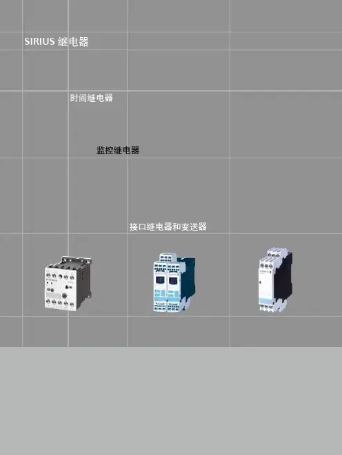
西门子SIRIUS继电器接口继电器和变送器
- 格式:pdf
- 大小:2.06 MB
- 文档页数:32
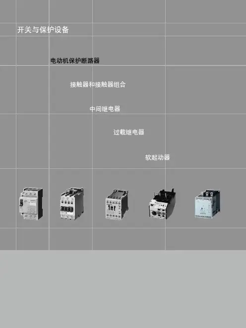
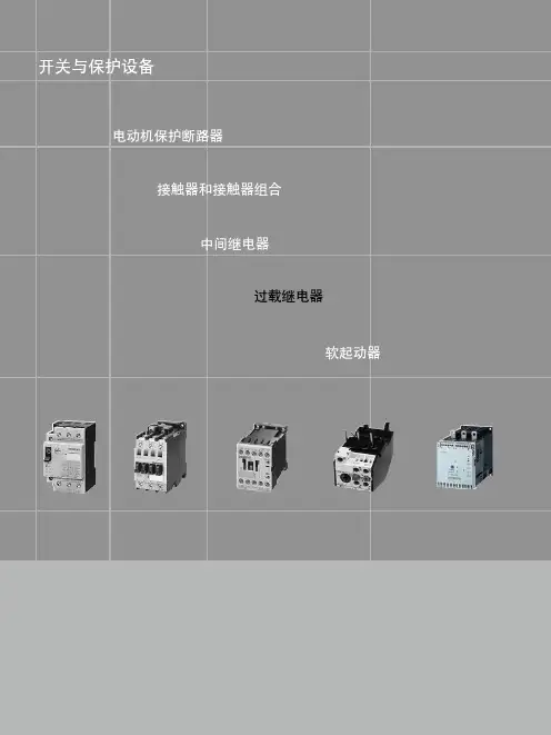
开关与保护设备SIRIUS (国产)3RV6/3RV5断路器1/2开关与保护设备电动机保护断路器接触器和接触器组合中间继电器过载继电器软起动器开关与保护设备SIRIUS (国产)3RV6/3RV5断路器1/2介绍√ 有此功能或可使用此附件- 没有此功能或不可使用此附件1) 适用于三相对称负载。
2)使用塑料防护罩附件时为交流 500 V 。
3)对于电动机过载保护,必须使用合适的过载继电器。
开关与保护设备SIRIUS(国产)3RV6/3RV5断路器1/3通用数据操作条件3RV6/3RV5 断路器适用于任何一种气候,应用于封闭空间正常操作环境中(例如无尘埃,无腐蚀性气体或有害气体)。
安装在灰尘和潮湿场所时,需要装配合适的防护罩。
3RV6/3RV5 断路器可以从顶部或底部进线。
断路器允许的环境温度、最大分断能力、脱扣动作电流和其它条件,参考本章具体技术数据和脱扣特性曲线。
3RV6/3RV5 断路器可以在 IT 系统(IT 网络)中使用,但应考虑到在 IT 系统中不同的短路分断能力。
即便是相同额定功率的电动机,由于瞬时峰值电流,其工作电流、起动电流以及电流峰值也是各不相同的。
因此,选择表格中的电动机额定值只能代表指导数据,电动机的实际额定数据和起动数据对选择合适的断路器是非常重要的。
这一原则同样适用于变压器保护用断路器。
应用类别3RV6/3RV5 断路器可用于:•电动机保护•系统保护•起动器组合短路保护•变压器保护•作为主开关和急停开关• IT 系统(IT 网络)•直流回路•防爆应用(ATEX)3RV6/3RV5 断路器为紧凑型限流电动机起动保护断路器,可用于三相感应电动机(交流 400 V 时功率最大至 45 kW)和其他负载(额定电流最大至 100 A)的开合和保护。
规格注释3RV6/3RV5 断路器包括 4 种规格:•S00 规格— 45 mm 宽,最大额定电流 16 A,交流 400 V 时适用感应电动机最大 7.5 kW。
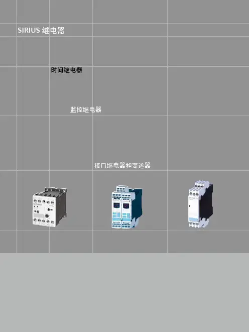
SIRIUS继电器9/102时间继电器SIRIUS 继电器监控继电器接口继电器和变送器SIRIUS 继电器9/2时间继电器3RP15/3RP20 时间继电器电子式 3RP1/3RP2 时间继电器可用于所有需要进行延时操作的起动、保护以及开环和闭环控制回路。
借助其业已验证的设计概念和紧凑的节约空间设计,成为所有工业领域中电气柜、面板和控制器厂家理想的定时设备选择。
通电延时:• 抑制噪声脉冲• 平稳起动电机,对线路电压冲击小断电延时:• 在断开控制电源后,仍能继续运行(风扇运转)• 电源故障时,可实现急停或将设备或系统置于一个特定的状态星/三角转换:• 为防止相间短路,电机需在50ms 内从星型电路转换到三角形电路• 所有型号都采用可拆卸端子• 所有型号都可选用螺钉型端子或笼卡式端子• 一套可选的标签用于标明多功能时间继电器所设定的功能• 7 种基本型号即能满足各种应用• 宽电压范围的多功能时间继电器,使用更为便利• 最佳的性价比• 强制断开,硬金镀层触点(可用于DIN EN 954 1 Category 2安全回路,并可和电子式控制系统配套使用)• 密封性外壳,可确保按设定参数运行SIRIUS 继电器9/3时间继电器3RP15/3RP20 时间继电器1)当设定“∞” 时,无延时功能,仅用于现场检测。
如:检测开关动作性能。
2)线圈电压工作范围 0.8 ~ 1.1 x U s 。
3)线圈电压工作范围 0.7 ~ 1.1 x U s 。
SIRIUS继电器9/4时间继电器3RP15/3RP20 时间继电器1)当设定“∞”时,无延时功能,仅用于现场检测。
如:检测开关动作性能。
2)线圈电压工作范围 0.7 ~ 1.25 x U s 。
3)线圈电压工作范围 0.85 ~ 1.1 x U s 。
4)线圈电压工作范围 0.8 ~ 1.1 x U s 。
SIRIUS 继电器9/5时间继电器3RP15/3RP20 时间继电器1)功能见 3RP1901-0 功能标牌套装。
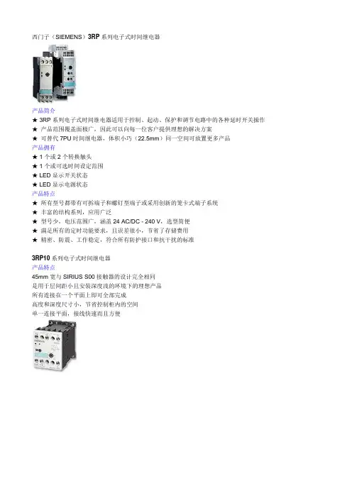
西门子(SIEMENS)3RP系列电子式时间继电器
产品简介
★ 3RP系列电子式时间继电器适用于控制、起动、保护和调节电路中的各种延时开关操作★产品范围覆盖面极广,因此可以向每一位客户提供理想的解决方案
★可替代7PU时间继电器,体积小巧(22.5mm)同一空间可放置更多产品
产品拥有
★ 1个或2个转换触头
★ 1个或可选时间设定范围
★ LED显示开关状态
★ LED显示电源状态
产品特点
★所有型号都带有可拆端子和螺钉型端子或采用创新的笼卡式端子系统
★丰富的结构系列,应用广泛
★型号少,电压范围广,涵盖24 AC/DC - 240 V,选型简便
★满足所有的定时功能要求,且误差很小,节省了存储费用
★精密、防震、工作稳定,符合所有防护接口和抗干扰的标准
3RP10系列电子式时间继电器
产品特点
45mm宽与SIRIUS S00接触器的设计完全相同
是用于层间距小且安装深度浅的环境下的理想产品
所有连接在一个平面上即可全部完成
高度和深度尺寸小,节省控制柜内的空间
单一连接平面,接线快速而且方便。
SIRIUS继电器时间继电器监控继电器接口继电器和变送器SIRIUS 继电器10/104SIRIUS继电器3UG4 监控继电器3UG4三相电压监控继电器•电压范围宽,它可以应用于从160V到690V的所有电源电压而无需辅助电压•可以灵活地设置成高范围、低范围或窗口控制•延时时间可调,手动/自动复位可选•所有型号的宽度均为 22.5mm,节省柜内空间•对于数字型监控继电器,可永久显示实际值和故障类型•所有型号都配有可拆卸端子•所有型号都可选用螺丝型端子或笼卡型端子新型3UG4监控继电器通过监控三相电压、单相电压和单相电流使电源、设备和系统获得最大程度的保护。
这意味着电源、电压和电流故障可以被及早检测出来,避免造成更大的损失。
断相熔断器熔断控制电源故障低电压电机电流增大,导致过热某设备意外复位电流监控过载监测在额定转矩附近进行欠载监测对电子负载的功能性进行监控断线监控能量管理(相电流监控)10/210/3SIRIUS继电器3UG4 监控继电器3UG4 三相电压监控继电器螺钉型螺子�笼卡型端子�12☐☐10/4SIRIUS继电器3UG4 监控继电器3UG4 三相电压监控继电器10/5SIRIUS 继电器3UG4 监控继电器3UG4 三相电压监控继电器10/610/7SIRIUS 继电器3UG4 监控继电器3UG4 三相电压监控继电器3UG45 11 监测继电器功能3UG45 11可监测三相电源的相序,而且可用于监测断相,但存在无法可靠检测由感性负载形成感应电压情况下断相的可能性。
时序图如下:3UG45 12 监测继电器功能3UG45 12 可监测三相电源的相序、断相及 10% 的相不平衡。
时序图如下:3UG45 13 监测继电器功能3UG45 13可监测三相电源的相序、断相、20%的相不平衡及低电压。
断电延时为 0.1~20s 可调。
电压迟滞为5% 。
时序图如下:SIRIUS继电器3UG4 监控继电器3UG4 三相电压监控继电器平衡及低电压。
sSIRIUS 3R–为新时代设计的时间继电器的设计理念源自于适配模数化模块系统,目前已产品家族的开发。
其中新一代时间继电器的特点是:适应用不同的工业行业,安装、使用迅速,操作简单,可靠性极高。
极佳的操作性能使 SIRIUS 3R 时间继电器特别适合于工业应用领域。
P R O D U C TD E S I G N A W A R D3RP15 时间继电器标准型紧凑设计的 3RP15 安装宽度仅 22.5mm , 具有绝大多数功能,辅助触头,时间及电压范围为标准设计,多档设置范围。
3RP10 时间继电器3RP10 的设计主要为配合电动机馈电装置,可与 S00 尺寸的接触器完美搭接。
3RP10 提供“通电延时”与“多功能”二种型式,每种都有 2 个电压范围 24V AC/DC ,100 - 127V AC 及 24V AC/DC ,200- 240V AC 。
3RP10 多功能型时间继电器有 7 个功能,由可换的编码插件实现。
“通电延时”型时间继电器已将功能固化,无须编码插件。
SIRIUS 3R - 针对馈电装置而设3RP10 时间继电器及 3RH 中间继电器均只有 45mm 宽。
且高度与深度相同,接线端子也具有相同高度,S00 系列的尺寸一致性与其他时间继电器相比可减少安装深度,故可降低对柜子深度的要求。
产品设计大奖高质量,高性能——现代安装技术的概念安装可靠,全球适用根据 IEC 947,继电输出在 AC15/DC-13 使用类别下可靠性极高,即使用于通断接触器也能实现很高的电气寿命,3RP 时间继电器的工作温度范围高达: -25°C ~ +50°C,高温工作可靠性高,符合全球相关安装标准,3RP10 时间继电器已通过 UL 及 CSA 标准。
使用 SIRIUS 3RP ——安装及连线方便,灵活所有新一代 SIRIUS 3RP1时间继电器均可安装于35mm 标准导轨,当然,也可螺钉安装,3RP10 无须附件,3RP15 的螺钉固定脚作为选购件。


SIRIUS继电器9/102时间继电器SIRIUS 继电器监控继电器接口继电器和变送器SIRIUS 继电器9/2时间继电器3RP15/3RP20 时间继电器电子式 3RP1/3RP2 时间继电器可用于所有需要进行延时操作的起动、保护以及开环和闭环控制回路。
借助其业已验证的设计概念和紧凑的节约空间设计,成为所有工业领域中电气柜、面板和控制器厂家理想的定时设备选择。
通电延时:• 抑制噪声脉冲• 平稳起动电机,对线路电压冲击小断电延时:• 在断开控制电源后,仍能继续运行(风扇运转)• 电源故障时,可实现急停或将设备或系统置于一个特定的状态星/三角转换:• 为防止相间短路,电机需在50ms 内从星型电路转换到三角形电路• 所有型号都采用可拆卸端子• 所有型号都可选用螺钉型端子或笼卡式端子• 一套可选的标签用于标明多功能时间继电器所设定的功能• 7 种基本型号即能满足各种应用• 宽电压范围的多功能时间继电器,使用更为便利• 最佳的性价比• 强制断开,硬金镀层触点(可用于DIN EN 954 1 Category 2安全回路,并可和电子式控制系统配套使用)• 密封性外壳,可确保按设定参数运行SIRIUS 继电器9/3时间继电器3RP15/3RP20 时间继电器1)当设定“∞” 时,无延时功能,仅用于现场检测。
如:检测开关动作性能。
2)线圈电压工作范围 0.8 ~ 1.1 x U s 。
3)线圈电压工作范围 0.7 ~ 1.1 x U s 。
SIRIUS继电器9/4时间继电器3RP15/3RP20 时间继电器1)当设定“∞”时,无延时功能,仅用于现场检测。
如:检测开关动作性能。
2)线圈电压工作范围 0.7 ~ 1.25 x U s 。
3)线圈电压工作范围 0.85 ~ 1.1 x U s 。
4)线圈电压工作范围 0.8 ~ 1.1 x U s 。
SIRIUS 继电器9/5时间继电器3RP15/3RP20 时间继电器1)功能见 3RP1901-0 功能标牌套装。
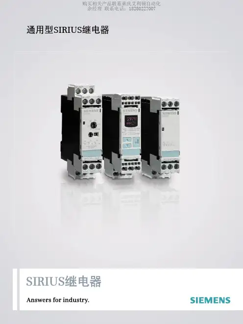
通用型SIRIUS 继电器2丰富的SIRIUS 继电器产品线:通用型继电器谈到控制器、负载馈电器和驱动器,每一位工程师都会想到要采用先进的技术。
而谈到继电器接口、控制继电器和监控继电器,又要另外花时间寻找供货商。
令人振奋的是,这一切已成为过去。
这是因为我们只需在同一个家族-SIRIUS -就可以得到所有这些产品:不但性价比高,而且选型简便。
源自西门子的SIRIUS 继电器系列,可满足所有有关电机启动方面的需要。
无论是时间继电器,还是监控继电器,无论是超薄型接口继电器、插入式继电器,还是小型接触器,我们都能提供通用型继电器来满足各种应用需求。
SIRIUS 继电器 — 完整的产品线满足各种应用需求。
主要特点:■ 适用于多种应用■ 用户界面友好■ 多功能性■ 性能充分考虑实际需求■ 极高的性价比完美的系统:无论是在生产环境、还是在输送系统中,无论是监控电机和设备,还是控制复杂的工厂或系统,SIRIUS 时间继电器、监控和接口继电器都能保证一切安全可靠运行。
43RP15/3RP20时间继电器导轨安装电子式3RP1/3RP2时间继电器可用于所有需要进行延时操作的启动、保护以及开环和闭环控制回路。
借助其业已验证的设计概念和紧凑的节约空间设计,成为所有工业领域中电气柜、面板和控制器厂家理想的定时设备选择。
应用:通电延时:■ 抑制噪声脉冲。
■ 平稳启动电机,对线路电压冲击小。
断电延时:■ 在断开控制电源后,仍能继续运行(风扇运转)。
■ 电源故障时,可实现急停或将设备或系统置于一个特定的状态。
星/三角转换:■ 为防止相间短路,电机需在50ms 内从星型电路转换到三角形电路。
优点:■ 所有型号都采用可拆卸端子。
■ 所有型号都可选用螺钉型端子或笼卡式端子。
■ 一套可选的标签用于标明多功能时间继电器所设定的功能。
■ 7种基本型号即能满足各种应用。
■ 宽电压范围的多功能时间继电器,使用更为便利。
■ 最佳的性价比。
■ 强制断开,硬金镀层触点(可用于DIN EN954 1 Category 2安全回路,并可和电子式控制系统配套使用)。

SIRIUS 软起动器:出色地保护电机和机械设备,减轻电网压力宣传手册• 2010SIRIUSAnswers for industry.SIRIUS — 适合各种应用的理想软起动器目前,三相电机通常作为用户最终选择的驱动形式。
但在很多情况下,直接起动或星三角起动等传统起动方式会引起机械冲击、电网电压骤降等问题。
为此,西门子公司推出了全系列的软起动解决方案,即 SIRIUS 软起动器,包括标准型和高性能型,可适用于任何应用场合。
SIRIUS 软起动器能够平稳起动/停止三相电机,轻松、高效的实现前瞻性的最佳设备解决方案。
2三相电机的软起动SIRIUS 软起动器—优点一览• 软起动,软停车• 平滑起动• 降低电机起动时的峰值电流• 避免起动过程中引起电网电压波动• 减轻电网压力• 减轻传动系统中的机械冲击• 与其它起动器相比,显著节省空间和布线• 降低维护费用• 操作简便• 可与其它 SIRIUS 设备完美搭配软起动器的工作原理软起动器通过限制起动电流和起动转矩,能够可靠地防止起动过程中的机械冲击和电网压降。
通过对可控硅导通角的控制,来降低电机起动电压,并在设定的起动时间内,将电机起动电压升高到额定电压。
凭借这种电机电压的无阶跃控制,可以根据被驱机器的负载特性对电机进行调节,平缓加速机械设备,从而显著提高机械设备的运行性能,延长其使用寿命。
总之:通过软起动/软停车,能够有效保护所连设备,确保生产运行平稳、可靠。
可以与负载馈电器配合使用吗?当然可以。
结合断路器,例如 SIRUIS 3RV,可以很容易地组成小型非熔断器保护的负载馈电装置。
不仅如此,由于该产品集成了过载保护功能,用户还可快速实现节省空间的带熔断器保护的负载馈电装置1)。
如何进行连接?连接方式与其它 SIRIUS 设备完全相同:使用螺钉型接线端子或弹簧型接线端子。
根据需要,也可使用其它连接方式。
能否进行通讯?当然。
西门子软起动器具有通讯功能。
Applications & Tools Answers for industry. Cover sheetIndustrial controlsSIRIUS InnovationsSafety-related Cntrols for a Load Feeder with IO-Link Connection in Category 2 according to EN 954-1 (with Evaluation according to EN 62061 andEN ISO 13849-1:2006)Assembly and Wiring with a SIRIUS 3TK28 Safety Relay Application description April 20102Safety-related Controls for a Load Feeder with IO-Link Connection in Category 2 according to EN 954-11.0 , Article ID: 42014643, Doc-ID: CE-FE-III-016-V10-ENC o p y r i g h t S i e m e n s A G 2010 A l l r i g h t s r e s e r v e dIndustry Automation and Drives Technologies Service & Support PortalThis document is available via the Siemens AG Industry Automation and Drives Technologies internet service portal. The document can be downloaded directly via the following link:/WW/view/en/42014643If you have any questions on this article, please contact us at the following e-mail address:online-support.automation@Safety-related Controls for a Load Feeder with IO-Link Connection in Category 2 according to EN 954-1 1.0 , Article ID: 42014643, Doc-ID: CE-FE-III-016-V10-EN 3C o p y r i g h t S i e m e n s A G 2010 A l l r i g h t s r e s e r v e dsSIRIUS InnovationsSafety-related Controls for a Load Feeder with IO-Link Connection in Category 2 according to EN 954-1Assembly and Wiring with a SIRIUS 3TK28 Safety RelayPreface 1Application description 2Wiring of the application 3Evaluation according to EN 62061 andEN ISO 13849-1:2006 4Further reading 5 History 6Guarantee and liability4Safety-related Controls for a Load Feeder with IO-Link Connection in Category 2 according to EN 954-11.0 , Article ID: 42014643, Doc-ID: CE-FE-III-016-V10-ENC o p y r i g h t S i e m e n s A G 2010 A l l r i g h t s r e s e r v e dGuarantee and liabilityNoteApplication examples are non-binding and do not claim to be complete with regard to configuration, equipment or to any contingency. The applicationexamples are not customer-specific solutions. They are merely intended to assist in dealing with typical problems. You are solely responsible for the correctoperation of the described products. These application examples do not relieve you of your responsibility for safe usage, installation, operation and maintenance. By using these application examples, you accept that we are not liable for any damage beyond the liability described. We reserve the right to make changes to these application examples at any time, without prior notice. If the suggestions in this application example deviate from other Siemens publications (e.g. catalogs), the contents of the other document have priority.We assume no liability for any of the information contained in this document. We are not liable for any damage caused by the use of the examples, information, programs, configuration and performance data, etc. described in this application example, independent of the legal ground upon which this is based, unless we are imperatively liable according to the product liability law, e.g. due to cases ofpremeditation, an act of gross negligence, injury to life, body or health, or unless the quality of a product has been guaranteed, or due to fraudulent concealment of a defect or serious breach of contract. Damages due to serious breach of contract are, however, restricted to prevalent and foreseeable contractual damages,inasmuch as there is no premeditation or gross negligence nor imperative liability due to injury to life, body or health. This does not constitute a change in the burden of proof to your disadvantage.Propagation or reproduction of these application examples or parts thereof is not permitted unless expressly allowed by Siemens Industry Sector.Table of contentsSafety-related Controls for a Load Feeder with IO-Link Connection in Category 2 according to EN 954-1 1.0 , Article ID: 42014643, Doc-ID: CE-FE-III-016-V10-EN 5C o p y r i g h t S i e m e n s A G 2010 A l l r i g h t s r e s e r v e dTable of contentsGuarantee and liability ................................................................................................4 1Preface................................................................................................................6 1.1 Objective of the application..................................................................6 1.2 Advantages / customer benefits...........................................................6 2Application description (7)2.1 Content.................................................................................................7 2.2 Assembly..............................................................................................8 2.2.1 Overview ..............................................................................................8 2.2.2 Requirements.......................................................................................8 2.2.3 Advantages of this solution..................................................................8 2.2.4 Required hardware components..........................................................9 3Wiring of the application (10)3.1 Content...............................................................................................10 3.2 Connecting.........................................................................................10 4Evaluation according to EN 62061 and EN ISO 13849-1:2006 (11)4.1 Safety function....................................................................................11 4.2 Evaluation according to EN 62061.....................................................12 4.3 Evaluation according to EN ISO 13849-1:2006.................................13 4.4 Summary............................................................................................14 5 Further reading................................................................................................15 5.1 Internet link information. (15)6History (16)Preface1.1 Objective of the application6Safety-related Controls for a Load Feeder with IO-Link Connection in Category 2 according to EN 954-11.0 , Article ID: 42014643, Doc-ID: CE-FE-III-016-V10-ENC o p y r i g h t S i e m e n s A G 2010 A l l r i g h t s r e s e r v e dPreface11.1Objective of the applicationThis application description describes the safety-related shutdown of the improved SIRIUS switching devices with IO-Link connection. The 24 V DC supply voltage of the function modules for the IO-Link is switched off via a 3TK28 safety relay.Core content of this applicationThe following core issues are discussed: • Assembly and wiring of the safety application •Evaluation of the safety functionBasic knowledge of this topic is required.Structure of the documentThe documentation of this application is divided into the following main parts.Table 1-1PartDescriptionApplication descriptionThis chapter gives you an overview. The required standard hardware components are introduced.Wiring of the application This section shows the electrical wiring of the application.EvaluationThis chapter contains information on the safety levels which the application fulfills according to the respective standards. Further readingThis chapter provides further information, e.g. literature references.1.2 Advantages / customer benefits• Pure hardware engineering without software configuration • Minimal and simple wiring•Space-saving design thanks to compact safety combinationApplication description2.1 ContentSafety-related Controls for a Load Feeder with IO-Link Connection in Category 2 according to EN 954-1 1.0 , Article ID: 42014643, Doc-ID: CE-FE-III-016-V10-EN 7C o p y r i g h t S i e m e n s A G 2010 A l l r i g h t s r e s e r v e dApplication description22.1 ContentIn this safety application example, the Emergency Stop control unit with a positive opening contact is monitored using a SIRIUS 3TK28 safety relay with contactor relays according to the following standards: • Category 2 according to EN 9541 • SIL 1 according to IEC 62061 • PL c according to ISO 13849-1When the Emergency Stop is activated, the safety relay initiates a shutdown via its contactor relays by means of a positively driven operation according to stop category 0 in compliance with EN 60204-1.Before renewed switch-on / acknowledgement of the Emergency Stop shutdown via the start button, a check is carried out to monitor whether the contact of the Emergency Stop control unit is closed and the contactors of the safety relay are switched off.Application description 2.2 Assembly8Safety-related Controls for a Load Feeder with IO-Link Connection in Category 2 according to EN 954-11.0 , Article ID: 42014643, Doc-ID: CE-FE-III-016-V10-ENC o p y r i g h t S i e m e n s A G 2010 A l l r i g h t s r e s e r v e d2.2 Assembly2.2.1OverviewA Category 2 example for the improved SIRIUS load feeders with IO-Linkconnection is shown in the following. The supply voltage of the function modules for the IO-Link is switched off via a 3TK28 safety relay. Feedback is given via the auxiliary switches of the contactorsFigure 2 -1 Assembly of the safety application2.2.2 RequirementsThe maximum output of the three-phase motor with connected reversing combination is 1.5 kW.The reversing combination is controlled via a 24 V DC supply.2.2.3 Advantages of this solutionThe reversing combination’s contactors are mechanically and electrically interlocked. Type of assignment 2 applies for this application example.Application description2.2 AssemblySafety-related Controls for a Load Feeder with IO-Link Connection in Category 2 according to EN 954-1 1.0 , Article ID: 42014643, Doc-ID: CE-FE-III-016-V10-EN 9C o p y r i g h t S i e m e n s A G 2010 A l l r i g h t s r e s e r v e d2.2.4 Required hardware componentsThe following table shows the minimum configuration of the hardware components.Table 2-2 Hardware componentsComponent TypeMLFB / order numberQuantity ManufacturerEmergency StopEmergency Stopmushroom pushbutton, 40 mm diameter, withpositive latching according to ISO 13850 and turn-to-reset mechanism, 2 NC with yellow top without protective collar3SB3801-0EG3 1Lock,two switching positions with two keys, latching, 1 NO 3SB3202-4AD11 1Acknowledge Empty enclosure for one switching element3SB3801-0AA3 1 Safety relay3TK28453TK2845-1BB40 1 Contactors Q1 and Q2Contactor, AC-3, 3 kW / 400 V,1 NC,24 V DC, 3-pole, size S00, communication-capable, screw terminal 3RT2015-1BB41-0C C02Function moduleFunction module for IO-Link, direct starter, screw terminal3RA2711-1AA00 2Contactors Q3 and Q4 Contactor, AC-3, 3 kW / 400 V,1 NC,24V DC, 3-pole, size S00, communication-capable, screw terminal3RT2015-1BB41-0C C02Function module Function module forIO-Link, reversing starter, screw terminal3RA2711-1BA00 1Installation kit for reversing combination• Mechanicalinterlocking• Two connection clipsfor two contactors • Wiring modules topand bottom Screw terminal3RA2913-2AA1 1SiemensWiring of the application 3.1 Content10Safety-related Controls for a Load Feeder with IO-Link Connection in Category 2 according to EN 954-11.0 , Article ID: 42014643, Doc-ID: CE-FE-III-016-V10-ENC o p y r i g h t S i e m e n s A G 2010 A l l r i g h t s r e s e r v e dWiring of the application33.1 ContentThis section shows the electrical wiring of the application.3.2 ConnectingThis chapter describes how the safety components are connected.Figure 3-2 Wiring of the safety componentsInstallation of the hardwareThe hardware components can be found in chapter 2.2.4.The structure of the hardware components is shown in chapter 2.2.1.Note The installation guidelines must always be observed.Evaluation according to EN 62061 and EN ISO 13849-1:2006C o p y r i g h t S i e m e n s A G 2010 A l l r i g h t s r e s e r v e dEvaluation according to EN 62061 and EN ISO 13849-1:200644.1 Safety functionComments• Emergency Stop is not a means of risk mitigation. • Emergency Stop is a “Supplementary Safety Function”Supplementary safety functionFurther considerations are based on the following supplementary safety function:Table 4-3Supplementary safetyfunctionSF 1The motor must be switched off when the Emergency Stop pushbutton is actuated.The safety function listed above is evaluated below according to the standards EN 62061 and EN ISO 13849-1:2006.Evaluation according to EN 62061 and EN ISO 13849-1:2006C o p y r i g h t S i e m e n s A G 2010 A l l r i g h t s r e s e r v e d4.2 Evaluation according to EN 62061Table 4-4 Parameters for the calculation of PFH D for “Detection” (Emergency Stop) and"Responding" (contactor)ParameterValue Reason DefinitionB10Emergency Stop 1 * 105 Manufacturer specifications Contactor1 * 106Proportion of hazardous failures Manufacturer specifications Emergency Stop 0.2 (20 %) Contactor 0.75 (75 %)T1Service life 175,200 hrs 20 years Manufacturer specificationsSiemensCAssumptions:Number of operations of Emergency Stop6 * 10-3 / hrsActuated once per week(7 * 24 hours)(Emergency Stop test). Actuations can take place every day of the year. Number of operations of contactors6 * 10-3 / hrsThe contactors are always activated and are only operated when theEmergency Stop is actuated. DCDegree of diagnostic coverage 0 (0 %)No fault reaction is initiated. (Worst case).UserTable 4-5 Evaluation parametersParameter Component ValueDefinitionPFH D (3TK)3TK28251.42 * 10-9 SiemensTable 4-6 SummaryEN 62061SIL CLPFH DDetect 1Hardware error tolerance: HFT = 0Proportion of safe failures: SFF = 0 (0 %) Use of proven components 1.2 * 10-9Architecture:Basic sub-system architecture A Evaluate 1 Manufacturer specifications 1.42 * 10-9Manufacturer specifications Respond 1Hardware error tolerance: HFT = 0Proportion of safe failures: SFF = 0 (0 %) Use of proven components4.5 * 10-10Architecture:Basic sub-system architecture AResult1SIL CL of all tasks of the supplementary safety function is at least 1. PFH D (= 3.05 * 10-9) of the entire supplementary safety function is less than SIL 1.Evaluation according to EN 62061 and EN ISO 13849-1:2006C o p y r i g h t S i e m e n s A G 2010 A l l r i g h t s r e s e r v e d4.3 Evaluation according to EN ISO 13849-1:2006Table 4-7 Parameters for the calculation of MTTF d for "Detection" (Emergency Stop) and"Responding" (contactor)ParameterValue Reason DefinitionB10Emergency Stop 1 * 105 Manufacturer specifications Contactor1 * 106Proportion of hazardous failures Manufacturer specifications Emergency Stop 0.2 (20 %)Contactor 0.75 (75 %)Siemens d opMean operating time in days per year 365 days per year h opMean operating time in hours per day24 hours per day Assumption:Actuation takes place every day of the year.t CycleMean time between the start of two consecutive cycles of the componentEmergency Stop 168 hrs / cycle Contactor168 hrs / cycleAssumption:There is an interval of one week between actuations of the Emergency Stop (Emergency Stop test) and contactors (7 * 24 hours)UserTable 4-8 Interim results (are identical in this example for Emergency Stop and contactor):Interim resultsReasonMTTF d High MTTF d ≥ 30 years DCNone DC = 0 % Measures against CCFNot relevant—Category 1System behavior: A single fault can result in the loss of the safety function.Table 4-9 Evaluation parametersParameter Component ValueDefinitionPFH D (3TK)3TK28251.42 * 10-9 SiemensEvaluation according to EN 62061 and EN ISO 13849-1:2006C o p y r i g h t S i e m e n s A G 2010 A l l r i g h t s r e s e r v e dTable 4-10 ResultEN ISO 13849-1:2006PLAverage probability of a hazardous failure per hourDetect c 1.14*10-6 (from Annex K; see note)Evaluate c 1.42 * 10-9Respond c 1.14*10-6 (from Annex K; see note)Result cPL of all tasks of thesupplementary safety function is at least c.Note The MTTF d for each channel is limited to a maximum of 100 years.4.4 SummaryTable 4-11 SummaryEN 62061EN ISO 13849-1:2006SIL CLPFH DPLAverage probability of a hazardous failureper hour Detect 1 1.2 * 10-9 c 1.14 * 10-6 Evaluate 1 1.42 * 10-9 c 8.7 * 10-9 Respond 1 4.5 * 10-10 c 1.14 * 10-6ResultSIL 1PL cFurther readingC o p y r i g h t S i e m e n s A G 2010 A l l r i g h t s r e s e r v e dFurther reading55.1Internet link informationThis list is not complete. It only provides a selection of possible further reading.Table 5-12Topic Title\1\ Link to the document /WW/view/en/42014643 \2\System manual Industrialcontrols – SIRIUS innovations/WW/view/en/39740306\3\Siemens A&DCustomer SupportHistoryC o p y r i g h t S i e m e n s A G 2010 A l l r i g h t s r e s e r v e dHistory6Table 6-13 History VersionDateChangeV1.0 01.04.2010 First issue。