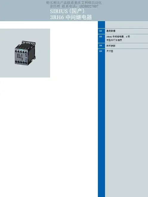
西门子安全继电器-SIRIUS 3TK3安全继电器模块
- 格式:pdf
- 大小:5.86 MB
- 文档页数:10


SIRIUS 软起动器:出色地保护电机和机械设备,减轻电网压力宣传手册• 2010SIRIUSAnswers for industry.SIRIUS — 适合各种应用的理想软起动器目前,三相电机通常作为用户最终选择的驱动形式。
但在很多情况下,直接起动或星三角起动等传统起动方式会引起机械冲击、电网电压骤降等问题。
为此,西门子公司推出了全系列的软起动解决方案,即 SIRIUS 软起动器,包括标准型和高性能型,可适用于任何应用场合。
SIRIUS 软起动器能够平稳起动/停止三相电机,轻松、高效的实现前瞻性的最佳设备解决方案。
2三相电机的软起动SIRIUS 软起动器—优点一览• 软起动,软停车• 平滑起动• 降低电机起动时的峰值电流• 避免起动过程中引起电网电压波动• 减轻电网压力• 减轻传动系统中的机械冲击• 与其它起动器相比,显著节省空间和布线• 降低维护费用• 操作简便• 可与其它 SIRIUS 设备完美搭配软起动器的工作原理软起动器通过限制起动电流和起动转矩,能够可靠地防止起动过程中的机械冲击和电网压降。
通过对可控硅导通角的控制,来降低电机起动电压,并在设定的起动时间内,将电机起动电压升高到额定电压。
凭借这种电机电压的无阶跃控制,可以根据被驱机器的负载特性对电机进行调节,平缓加速机械设备,从而显著提高机械设备的运行性能,延长其使用寿命。
总之:通过软起动/软停车,能够有效保护所连设备,确保生产运行平稳、可靠。
可以与负载馈电器配合使用吗?当然可以。
结合断路器,例如 SIRUIS 3RV,可以很容易地组成小型非熔断器保护的负载馈电装置。
不仅如此,由于该产品集成了过载保护功能,用户还可快速实现节省空间的带熔断器保护的负载馈电装置1)。
如何进行连接?连接方式与其它 SIRIUS 设备完全相同:使用螺钉型接线端子或弹簧型接线端子。
根据需要,也可使用其它连接方式。
能否进行通讯?当然。
西门子软起动器具有通讯功能。
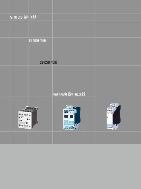
SIRIUS继电器时间继电器监控继电器接口继电器和变送器SIRIUS 继电器10/104SIRIUS继电器3UG4 监控继电器3UG4三相电压监控继电器•电压范围宽,它可以应用于从160V到690V的所有电源电压而无需辅助电压•可以灵活地设置成高范围、低范围或窗口控制•延时时间可调,手动/自动复位可选•所有型号的宽度均为 22.5mm,节省柜内空间•对于数字型监控继电器,可永久显示实际值和故障类型•所有型号都配有可拆卸端子•所有型号都可选用螺丝型端子或笼卡型端子新型3UG4监控继电器通过监控三相电压、单相电压和单相电流使电源、设备和系统获得最大程度的保护。
这意味着电源、电压和电流故障可以被及早检测出来,避免造成更大的损失。
断相熔断器熔断控制电源故障低电压电机电流增大,导致过热某设备意外复位电流监控过载监测在额定转矩附近进行欠载监测对电子负载的功能性进行监控断线监控能量管理(相电流监控)10/210/3SIRIUS继电器3UG4 监控继电器3UG4 三相电压监控继电器螺钉型螺子�笼卡型端子�12☐☐10/4SIRIUS继电器3UG4 监控继电器3UG4 三相电压监控继电器10/5SIRIUS 继电器3UG4 监控继电器3UG4 三相电压监控继电器10/610/7SIRIUS 继电器3UG4 监控继电器3UG4 三相电压监控继电器3UG45 11 监测继电器功能3UG45 11可监测三相电源的相序,而且可用于监测断相,但存在无法可靠检测由感性负载形成感应电压情况下断相的可能性。
时序图如下:3UG45 12 监测继电器功能3UG45 12 可监测三相电源的相序、断相及 10% 的相不平衡。
时序图如下:3UG45 13 监测继电器功能3UG45 13可监测三相电源的相序、断相、20%的相不平衡及低电压。
断电延时为 0.1~20s 可调。
电压迟滞为5% 。
时序图如下:SIRIUS继电器3UG4 监控继电器3UG4 三相电压监控继电器平衡及低电压。

Which sensors can be connected?SIRIUS ACT EMERGENCY STOP 3SU18command devicesSIRIUS 3SE29/39 foot switchesSIRIUS ACT 3SU1 two-hand operation consolesSIRIUS 3SE7cable-operated switchesSIRIUS 3SE5 position and safety switchesSIRIUS 3SE6 non-contact safety switchesIntegrated and efficientsafety chain2SIRIUS 3RT contactorsSIRIUS 3RA6 compact startersSIRIUS 3RM1 motor startersFrom detecting to evaluating and reacting.Sensors and actuators work together perfectly to create the ideal conditions for complete safety chains with SIRIUS Safety. These chains are not only extremely reliable but are also much quicker and easier to set up.An important element are the position and safety switches.P r o t e c t iv ed o o rE m e r g e n c ys t o pL i g h t a r r a yL a s e r s c a n n e rM a tT w o -h a n dc o n t r o lpa n e lT i m e -d e l a y e ds h u t d o wn P r o t e c t i v e d o o rw i t hl o c k i n gd e v i c eI n d e p e n d e n to u t p u tf u n c t i o nsM u t i n g1234EN 50 047Main advantages at a glance• Reduced variance and stock-keeping costs due to modular design• Plug-in design and a standardized interface simplify replacement and installation of the actuator heads • All actuator heads can be rotated in 22.5° increments • Quick-connect technology for plastic enclosures (31 mm) reduces mounting times by up to 25%• Choice of connectors and rollers• The entire ASIsafe electronics is integrated in a standard enclosure• LED displays optionally available for all enclosures • Higher degree of safety with redundant shutdown and additional signaling for versions with 3-pole contact blocks (enclosure dimensions as for 2-pole contact blocks)• Versions with increased corrosionprotection and for use down to –40°CSIRIUS position switches4Complete unitsPlastic or metal enclosure 31 mm wide, according to EN 50 047, with snap-action contacts 1 NO / 1NCRounded plunger, high-grade steel––Roller plunger X–Roller lever–X 3SE5122-0CH01Twist lever–X3SE5122-0CH50Twist lever, infinitely adjustable length–X= p ositive opening* – =withhigh-gradesteel roller** – =withplasticroller Our position switches can be ordered in a modular design or as complete units – already fitted with an actuator head. You will find further versions, such as compact switches, non-encapsulated designs or switches for ambient temperatures down to –40°C at: /sirius/configurators5Mechanical safety switcheswith separate actuatorsSafety switches with a separate actuator are used where the position of doors, covers or protective grilles must be monitored for safety reasons. 3SE5 safety switches with a separate actuator without a locking device have the same enclosures as the 3SE5 position switches (modular system). Safety switches with a locking device 3SE53 are special safety-related devices which prevent an unforeseen or intentional opening of protective doors, protective grilles or other covers for as long as a dangerous situation is present (i.e. follow-on motion of the switched-off machine).63SE5000-0AB01–––3SE5000-0AD053SE5000-0AC03–––3SE5000-0AE05––3SE5000-0AF05–3SE5000-0AR01––+3SE5000-0AH00++–3SE5000-0AA013SE5000-0AA02–3SE5000-0AA113SE5000-0AA12–3SE5000-0AA503SE5000-0AA51–3SE5000-0AA603SE5000-0AA613SE5000-0AA80––3SE5000-0AA82––= p ositive openingPlain plunger Rounded plunger Roller plunger Roller lever Angular roller lever Spring rod Twist actuatorAdjustable-lengthtwist lever7Plain plungerRounded plunger (with overtravel)Roller plunger (with overtravel)Roller leverAngular roller leverSpring rod Twist actuatorAdjustable-lengthtwist lever3SE5000-0AB01––3SE5000-0AC02––––3SE5000-0AD02–3SE5000-0AE013SE5000-0AE02–3SE5000-0AE033SE5000-0AE04–3SE5000-0AF013SE5000-0AF02–3SE5000-0AF033SE5000-0AF043SE5000-0AR01–– +3SE5000-0AH00++–3SE5000-0AA013SE5000-0AA02–3SE5000-0AA113SE5000-0AA12–3SE5000-0AA503SE5000-0AA51–3SE5000-0AA603SE5000-0AA613SE5000-0AA80––3SE5000-0AA82––= p ositive opening8Non-contact RFID safety switches: An RFID safety switch consists of a coded RFID switch with an 8-pole M12 3SE6315-0BB02-1AP0Individually coded, multiple teach-in capability3SE6315-0BB03-1AP0Individually coded, single teach-in3SE6310-0BC01StandardNon-contact RFID safety switches with tumbler, locking force 1150N: An RFID safety switch with tumbler 3SE6415-1BB02Closed-circuit principle, individually coded, multiple teach-in capability3SE6415-1AB01Open-circuit principle, family coded3SE6415-1AB02Open-circuit principle, individually coded, multiple teach-in capability3SE640-1AC01Standard*Connection cable for both types of safety switches available in 3, 5, 10 and 15 metersNon-contact safety switchesThe SIRIUS 3SE63 RFID safety switches without tumbler and magnetically-operated switches and the 3SE64 RFID safety switches with tumbler and magnetically-operated switches leave no room for tampering. They conform to market safety requirements with maximum tamper resistance according to ISO 14119 as well as safety requirements according to SIL 3 (IEC 62061/IEC 61508) or PL e (ISO 13849-1) for monitoring the positions of movable protective devices.In the case of protective door tumblers, 3SE64 RFID safety switches provide reliable protection against dangerous follow-on motion and are suitable for protecting both people and processes. The unique rotating shaft and hub operating principle makes it possible to pull the protective door shut (latch force can be set to 25 N or 50 N) to an almost backlash-free end posi-tion with a simultaneous tumbler that even serves as a door stop, eliminating the need for an additional door stop.Non-contact magnetically operated safety switch: A magnetically operated switch comprises a coded switching 3SE6604-2BA With cable 3 m, 2NC 3SE6604-2BA01With M8 plug, 4-pole, 2NC 3SE6604-2BA10With cable 10 m, 2NC 3SE6605-2BA With cable 3 m, 1NO +1NC 3SE6605-2BA01With M8 plug, 4-pole, 1NO +1NC 3SE6614-4CA01With M8 plug, 4-pole, 2NC, LED3SE6704-2BA For 3SE660* versions 3SE6714-2BA For 3SE661* versions 3SE6605-3BA With cable 3 m, 1NO +1NC 3SE6605-3BA05With cable 5 m, 1NO +1NC 3SE6605-3BA10With cable 10 m, 1NO +1NC3SE6616-3CA01With 8 mm latching connection, 6-pin connector, 1NO +1NC +1NC 1)3SE6617-3CA01With 8 mm latching connection, 6-pin connector,1NO +1NC +1NC 1)3SE6627-3CA04With cable 3 m, 2NC +1NC 1)3SE6704-3BA For 3SE660* versions 3SE6714-3CA For 3SE661*/3SE662* versions3SX5601-3GA05 5 m, M8 socket, 4-pole3SX5601-4GA055 m, socket 8 mm, latching connection 6-pole 1)Signaling contact9SIL 3/PL eSIL 3/PL eSIL 3/PL eSIL 3/PL eSIL 3/PL eSIL 3/PL eWith 2x switches(enabling individual switch combinations)Maximum safetySafety Integrity Level SIL (IEC 62061/ IEC 61508)/Performance-Level PL (ISO 13849-1)With 1x switchMonitoring of 1 NO contactMonitoring of 1 NO contactMonitoring of 1 NO contactMonitoring of 2 NO contacts or 1 NO and 1 NC contactMonitoring of 2 NO contacts or 1 NO and 1 NCcontact Monitoring of 2 NO contacts or 1 NO and 1 NC contact SIL 1/PL c SIL 1/PL c SIL 1/PL c SIL 1/PL c SIL 2/PL d SIL 2/PL d Design type112Mechanical position and safety switchesSIMATIC ET 200SPSIRIUS 3SK safety relaysSIMATIC controllerSafety switches with separateStandard/compact 3SE51/3SE52/3SE54 3SF1 AS-i variantTampering protection(Acc. to DIN EN ISO 14119, TÜV certificate)low,actuator head uncoded Positive opening operation as per IEC 60947-5-1, positive drive, necessary in safety applicationslow,shaft uncoded low,3D-coded actuator without tumbler 3SE51/3SE52 3SF1 AS-i variantSafety hinge 3SE51/3SE52 3SF1 AS-i variantDetectingEvaluatingApplication examplesWith the position and safety switches almost all requirements in the industry can be met.Various application examples e.g. forguard door monitoring can be found here:Position switch with twist lever:Detection of positions and end positions of moving machine and system parts, such as e.g. conveyor belts and assembly linesPivoting doors and flaps, with fixedpositive connection between switch and door hinge, switching angle 10°Roller door or position monitoring of grilles or doors/cs/ww/en/ps/16403/ae/et200sp/safety-relays /simatic-safety1.) Without tumbler2.) W ith lockingdeviceSIRIUS Position and Safety Switches10SIL 3/PL e SIL 3/PL e Monitoring of 1 NO contact Monitoring of 2 NO contacts or 1 NO and 1 NC contactMonitoring of 2 NO contacts or 1 NO and 1 NC contact Self-monitoring with 2 electronic 0SSD safety outputsSelf-monitoring with 2 electronic0SSD safety outputs SIL 1/PL c SIL 3/PL e SIL 3/PL eSIL 3/PL eSIL 2/PL d 2444 actuatorNon-contact safety switches low, 3D-coded actuatorlow, coded switching magnet low or high (to choose), coded RFID security switches low or high (to choose), coded RFID security switches Magnet safety switches 3SE66/3SE67with tumbler 3SE53 3SF1 AS-i variant RFID safety switches 3SE63RFID safety switches with tumbler 3SE64Additional interlocking requirement, e.g. in the working area of a robot system: Shutdown of machines requires closed safety doors with tumbler guarding Monitoring of maintenance flaps (hoods, doors, grilles), especially suitable for confined spaces Monitoring of swing doors, flaps, hoods, grilles, vibration-proof and robust IP69, large switching interval Interlocking requirement for rotating, laterally movable or removable safety guards IP69, with latching, optimized hygiene standard with simultaneous highest personnel and process protection Application manual SIRIUS Safety IntegratedDownload here11Technical information and support are available at/SIOSor in the Industry Online Support App.Available for Android and iOsr e l y generalf or m a nce which in case of ac t p ly ast her de v e lpmSecurity information/industrialsecurity.。

/controlsStart-up with a small footprintSIRIUS 3RM1 Motor Starter – multifunctional with a width of just 22.5 mmSIRIUS HybridGetting started –even when things get tight:SIRIUS 3RM1 Motor StartersSpace-saving systems require maximum efficiency and can pose significant challenges for system engineers. Systems and machinery are becoming in-creasingly compact and are expected to have smaller footprints, but at the same time they typically require more auxiliary drives. Because every inch counts in a control cabinet, SIRIUS 3RM1 Motor Starters are precisely tailored to meet these requirements and represent the solution for the development of cutting-edge and future-oriented systems.Their innovative housing concept even received the internationally renowned iF product design award 2013. It’s easy to get started: The new motor starters are so narrow that they fit into the smallest space.In brief: SIRIUS 3RM1 Motor Starters – multifunctional with a width of just 22.5 mm.The SIRIUS 3RM1 Motor Starters are designed for installation in control cabinets and require minimal space: They combine the functionality of con-tactors and overload relays in a width of just 22.5 mm. In addition, thanks to their use of hybrid switching technology, they have all the benefits of the relay and semiconductor technology in a single device, which increases their cost-effectiveness.The motor starters make your work easier by offering easy adjustment of motor current, minimal wiring costs, and fast troubleshooting. With these motor starters, you can build more com- pact control cabinets and increase the efficiency of your systems while saving time and money in the installation.3RM1 motor starters can optionally be used in combination with a fuse module for short-circuit protection on all 60 mm busbar systems using a range of adapters.Direct or reversing starting – with SIRIUS 3RM1 Motor Starters, you can implement compact control cabinet solutions for small motors up to 3 kW.2Economical• Durable and energy-efficienthybrid switching technology • Low device variance through wide adjustment rangeCompact• Narrow width • Multifunctionality– D irect and reversing starters – O verload protection – Safe shutdownSimple• Less wiring– i n control circuit thanks to device connectors – i n main circuit with the infeed system • Fast diagnostics• Compact mounting on busbar systems using the 3RM19 fuse module3Conventional reversing starterCon- tactorContactor140 m m90 mm100 m m22.5 mmOverload relayNarrow widthThe motor starters are distinguished by their narrow width of just 22.5 mm. That saves room in the control cabinet and provides the ideal conditions for systems and machines with many small motors up to 3 kW.Even subsequent expansions are easier to plan and imple-ment: If more motors are needed in the system, thanks to their narrow width it’s easy to add additional SIRIUS 3RM1 Motor Starters to the ones already installed in the control cabinet.The new motor starters optimally round out the SIRIUS portfolio of industrialcontrols technology: They combine several functions – such as direct or reversing start, overload protection, and safe shutdown – into a uniformly compact and extremely narrow housing.Conventional direct starter140 m m45 mm100 m m22.5 mm Conventional reversing starter with safetyContactorOverload relay185 m m90 mm100 m m22.5 mmContactorCon- tactorScan and learn more about space savings in control cabinets!4Safe shutdownTo meet the requirements for safe shutdowns, SIRIUS 3RM1 Motor Starters are also available in a safety version. They can be used in combination with the modular safety relays to easily implement locally limited safety applications.The motor starters for safe shutdowns are available as direct and reversing starters.They are certified in accordance with SIL 3/PL e Cat. 4.MultifunctionalDirect and reversing startersMotor starters are available as direct starters or with a re-versing starter function, all in a uniform housing design. The operation, configuration, and the width for both device types are identical.Overload protectionEvery motor starter is equipped with integrated electronic overload protection. In other words, you no longer need a separate overload relay when you use these motor starters. The result is lower wiring costs, shorter installation time and more room on the DIN rail.The motor overload protection of the safety version is ATEX certified, which means that it can also be used for motors in explosion-proof areas with flammable dust and gases.5Durable and energy-efficientHybrid switching technology uses low-wear semiconductor technology for turning the motor on and off; during operation, it uses energy-efficient relay technology. That pro-vides durability, particularly in cases of high switching frequency. This technology signifi-cantly reduces maintenance costs and ex-tends the service life of the motor starters. In addition, thanks to the hybrid switching technology, the motor starters have a lower level of electromagnetic interference, which increases the availability of your systems.Further energy savings are provided by the integrated electronic overload protection. It causes a lower intrinsic power loss than com-parable motor feeders with thermal overload protection. In this way, you benefit from re-duced heat generation and therefore lower cooling power. That saves energy.Flexible useSIRIUS 3RM1 Motor Starters give you greater latitude when it comes to project planning as well as motor replacements: You can use a rotary encoder switch to easily set the motor starters in their specific adjustment range to the current of the connected motor.That reduces the number of device variants and saves on storage space and handling costs. Moreover, your options are kept open for longer when planning and engineering motors and control cabinets. And, if a motor is later replaced by a more powerful or less powerful model, in most cases you can simply readjust the existing motor starter and do not need to replace it.Increase the efficiency in the control cabinet with energy-efficient and durable tech- nology and benefit from a clear spectrum of devices.The hybrid switching tech- nology of the motor starters combines the benefits of relay technology with those of semiconductor technology, making it particularly energy- efficient while offering low wear and low interference.✓Service lifeScan and experience the benefits of hybrid switching technology!6Reduced wiringControl circuitFor simultaneous safety-oriented tripping of multiple motor starters via a SIRIUS 3SK safety relay, you can simply interconnect devices using a device connector, without any wiring. This also relays the power supply.Main circuitThe power supply in the main circuit for mul-tiple motor starters can be handled quickly, simply, and safely via a special system: The motor starters are interconnected via 3-phase busbars and powered via a 3-phase infeedterminal. The special shape of the busbars allows quick and simple removal of individual devices from the infeed network.Simple design of load feedersVery compact load feeders with a narrow width of just 22.5 mm can be implemented using the fuse module. A corresponding adapter connects the module to the busbar system. The plug-in connection makes it even easier to replace motor starters, for example, if outputs need to be adjusted. Expansions can easily be added later into spare slots without having to install power supply cables.Save time during installationthanks to simple wiring, and duringoperation thanks to clear statusindication. Whether for configur-ing, installation or maintenance –these motor starters make every-thing easier for you.Simple connectionYou benefit from convenient connectionswhen wiring the devices. The screw-typeterminals for the control circuit have anoptimized insertion angle so that tooland cable can be inserted from the samedirection. The spring-loaded terminals arewired without tools: simply insert the cablemanually – done!If necessary, you can individually swapout the removable connection terminalson the unit.Easy-to-read status indicatorThanks to the LED status indicator on thehousing of the SIRIUS 3RM1 Motor Starters,you can see at a glance whether all thefunctions are in operation or if there are anyproblems. This makes it possible to quicklydetect and correct any faults.SIRIUS 3RM19 fusemoduleSIRIUS 3RM1 motorstarterAdapter for busbarsystemAdapter for compactbusbar systemCover profiles forbusbarsThe optional fuse module canbe used to create completeload feeders.7Diverse range of applicationsSIRIUS 3RM1 Motor Starters can be used inmany industrial areas to control auxiliarymotors, such as for pumps, fans, and hoist-ing equipment, in machine tool and produc-tion machines, as well as in conveyor tech-nology. The devices are optimally suitedfor group configurations in which multiplemotor starters can be protected by onlyone circuit breaker.The motor starters for safe shutdown canbe flexibly combined with a wide varietyof safety relays and fail-safe controls.Scan und experiencethe safe shutdown ofa system for yourself!Ideal addition to the SIRIUS switching technology portfolioThe SIRIUS portfolio is ideally positioned for higher switching currents. The new motor starters perfectly round out the existing SIRIUS industrial switching tech-nology portfolio in the field of smaller motors. With a width of just 22.5 mm, the new SIRIUS 3RM1 Motor Starters are perfect for control cabinets where space is at a premium.SIRIUS 3RM1 Motor Starters can be used with a wide range of motorsup to 3 kW. They are particularly well suited for use in machine tool and production machine construc-tion – whether as an individual device, or as components in a group design for applications with or with-out safe shutdown requirements.8Group design for a conveyor systemWith SIRIUS 3RM1 Motor Starters, you can quickly and easily implement group installa-tions with integrated overload protection for a wide range of applications – one example would be for conveyor systems with numer-ous electric motors. In the main circuit, the three-phase feeder terminal and three-phase busbar supply the motor starters, eliminating the need for complex wiring for the infeed. In a group design, a single circuit breaker can provide short circuit protection up to 55 kA.Significant provisions are in place for the ex-pansion of the conveyor system – the infeed system has the flexiblility to be expanded, allowing additional motor starters to be in-tegrated into an existing group design with minimal effort. Project planning is simplified through the new motor starter configurator.Safe shutdown in a filling systemThe combination of fail-safe SIRIUS 3RM1 Motor Starters with SIRIUS 3SK Safety Relays makes it easy to implement locally limited safety applications. One example can be found in the protective door monitoring of a machine, that safely shuts down when the protective door is opened.To accomplish this, the motors of the pumps are connected to the new motor starters. On the control current side, the motor starters are connected to a SIRIUS 3SK Safety Relay via the device connector. If the monitored door is opened, the safety relay receives a signal from a connected non-contact safety switch, evaluates it, and sends the informa-tion to all the motor starters in the group via the device connector. The fail-safe motor starters react by safely shutting down allconnected motors.Combination of one SIRIUS 3SK safety relay and four motor start-ers for a safe group shutdown.The infeed system supplies group configurations up to a total current of 25 A.9Innovative housing conceptDevice connectorEasy, wireless connection of mul-tiple motor starters for connecting to SIRIUS 3SK Safety Relays for safe shutdownLabeled hinged coversSimple orientation thanks to laser labeling for the individual connections in the coverWidthEconomical, space-saving width of just 22.5 mmSealable coverSimple protection against unauthorized access2D matrix codeFast and easy scanning of order and serial numbers; corresponding Siemens app available at/sirius/support-appScrew-type connectionConnection terminalsEasily replaceable connection ter-minals, available with screw-type or spring-loaded technologySpring-loaded connectionRotary encoder switchEasy setting of the motor current to be monitored Test/reset buttonAcknowledgement if a malfunction occurs 1. R eset in case of overload 2. I mplement the test function 3. S witch from manual to automatic resetLED status indicatorFast, selective start-up, and clear LED error display10Step 1:To find the right motor starter, you first need to decide whether you need a device with or without the integrated safety func-tion as well as whether you want a direct ora reversing starter.Step 2:Decide between the three motor current ranges 0.1 … 0.5 A; 0.4 … 2.0 A; and1.6 … 7.0 A (even for resistive loads of up to 10 A). You can subsequently set the level of the motor current to be monitored via the rotary encoder switch on the motor starter – and if the application changes, you can make adjustments within the specific wide setting range.Step 3:For additional product specification, choose between the two control voltages 24 V DC and 110 – 230 V AC, 110 V DC.Step 4:Finally, you need to decide which connection technology you prefer: spring-loaded con-nections or screw-type connections.All the product data you need for planning your control cabinet is available free of charge via CAx Download Manager: Available data includes 3D models, dimension draw-ings, manuals, and .edz macros for EPLAN Electric P8. For more information, visit /planning-efficiencyThe right type for youOrder number overviewSIRIUS 3RM1 Motor Starter1) Base 4-pin with AC 400 V; the concrete start-up and rated data of the motor should be taken into consideration for the selection2) Operation of ohmic loads with a maximum of 10 A3) Control circuit implemented as a push-in spring-loaded connection and main circuit as a screw-type connection11Siemens Industry Inc.3617 Parkway LanePeachtree Corners, GA 300921-866-663-7324*******************Subject to change without prior noticeOrder No.: CPBR-3RM1-0820Article No.: DFCP-B10060-01-7600All rights reservedPrinted in USA© 2020 Siemens Industry, Inc.The technical data presented in this document is based on an actual case or on as-designed parameters, and therefore should not be relied upon for any specific application and does not constitute a performance guarantee for any projects. Actual results are dependent on variable conditions. Accordingly, Siemens does not make representa-tions, warranties, or assurances as to the accuracy, currency or completeness of the content contained herein. If requested, we will provide specific technical data or specifications with respect to any customer’s particular applications. Our company is constantly involved in engineering and development. For that reason, we reserve the right to modify, at any time, the technology and product specificationscontained herein.。
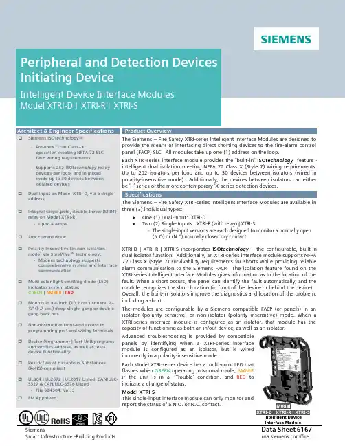
Siemens Data Sheet 6167 Smart Infrastructure -Building Products /fire The Siemens – Fire Safety XTRI-series Intelligent Interface Modules are designed to provide the means of interfacing direct shorting devices to the fire-alarm control panel (FACP) SLC. All modules take up one (1) address on the loop.Each XTRI-series interface module provides the “built -in” ISO technology feature - intelligent dual isolation meeting NFPA 72 Class X (Style 7) wiring requirements. Up to 252 isolators per loop and up to 30 devices between isolators (wired in polarity-insensitive mode). Additionally, the devices between isolators can either be ‘H’-series or the more contemporary ‘X’-series detection devices.The Siemens – Fire Safety XTRI-series Intelligent Interface Modules are available in three (3) individual types:⑥ One (1) Dual-Input: XTRI-D⑥Two (2) Single-Inputs: XTRI-R (with relay) | XTRI-S - The single-input versions are each designed to monitor a normally open(N.O) or (N.C) normally closed dry contact XTRI-D | XTRI-R | XTRI-S incorporates ISO technology – the configurable, built-indual isolator function. Additionally, an XTRI-series interface module supports NFPA 72 Class X (Style 7) survivability requirements for shorts while providing reliable alarm communication to the Siemens FACP. The isolation feature found on the XTRI-series Intelligent Interface Modules gives information as to the location of the fault. When a short occurs, the panel can identify the fault automatically, and the module recognizes the short location (in front of the device or behind the device). Overall, the built-in isolators improve the diagnostics and location of the problem, including a short.The modules are configurable by a Siemens compatible FACP (or panels) in an isolator (polarity sensitive) or non-isolator (polarity insensitive) mode. When a XTRI-series interface module is configured as an isolator, that module has the capacity of functioning as both an in/out device, as well as an isolator.Advanced troubleshooting is provided by compatible panels by identifying when a XTRI-series interface module is configured as an isolator, but is wired incorrectly in a polarity-insensitive mode.Each Model XTRI-series device has a multi-color LED that flashes when GREEN operating in Normal mode; AMBER if the unit is in a `Trouble’ condition, and RED toindicate a change of status.Model XTRI-SThis single-input interface module can only monitor and report the status of a N.O. or N.C. contact.ModelXTR I -D | XTR I -R | XTR I -SIntelligent Device Interface Module☐Siemens ISO technology TM - Provides “True Class–X”operation meeting NFPA 72 SLC field wiring requirements - Supports 252 ISO technology ready devices per loop, and in mixed mode up to 30 devices between isolated devices ☐Dual input on Model XTRI-D, via a single address☐ Integral single-pole, double-throw (SPDT) relay on Model XTRI-R: - Up to 4 Amps. ☐ Low current draw☐ Polarity insensitive (in non-isolation mode) via SureWire TM technology: - Modern technology supports comprehensive system and interfacecommunication☐ Multi-color light-emitting diode (LED)indicates system status: GREEN | AMBER | RED☐Mounts in a 4-inch (10.2 cm.) square, 2–¼” (5.7 cm.) deep single -gang or double-gang back box☐ Non-obstructive front-end access toprogramming port and wiring terminals ☐ Device Programmer | Test Unit programs and verifies address, as well as tests device functionality☐Restriction of Hazardous Substances (RoHS) compliant☐ UL864 | UL2572 | UL2017 Listed; CAN/ULC-S527 & CAN/ULC-S576 Listed- File S24304, Vol. 3☐FM ApprovedSiemensSmart Infrastructure – Building Products –2– /fireModel XTRI-RThrough the use of an addressable ‘Form C’ relay, the Model XTRI-R relay and contact device input are controlled at the same address. The relay and input contact can be controlled as a separate function from a Siemens compatible FACP. The relay is typically used where control or shunting of external equipment is required.Model XTRI-DModel XTRI-D is a dual-input module that is designed to supervise and monitor two (2) sets of dry contacts. Model XTRI-D only requires one (1) address, but responds independently to each input. Model XTRI-D is ideal for monitoring a water-flow switch and its respective valve tamper switch.Field-Device Programmer / Test UnitSiemens – Fire Safety innovative technology allows Model XTRI-series intelligent interface modules to be programmed via the Siemens field-device programmer / test unit (Model DPU), which is a compact, portable and menu-driven accessory for electronically programming and testing Siemens peripheral modules and devices promptly and reliably. For instance, the field technician selects the accessory’s program mode, and enters the desired address.Model XTRI-series interface module is connected to Model DPU with the programming cable provided with the tester.NOTE: Since the XTRI-series of interface modules are advanced initiating devices, the latest Model DPU firmware update isrequired.Model DPU eliminates the need for cumbersome, unreliable mechanical programming methods (e.g. – dials and rotary switches), and reduces installation and service costs by electronically programming and testing the module prior to installation. When set in `test’ mode, Model DPU will perform a series of diagnostic tests without altering the address or other stored data, allowing technicians to determine if the module is operating properly.Each field-device programmer / test unit operates on AC power or rechargeable batteries, providing flexibility and convenience in the programming / testing of fire-safety equipment from practically any location. Additionally, with the use of a Model DPU unit, there is no longer a cause for concern with any vibration, corrosion and other deteriorating conditions that could negatively affect any electro-mechanical-addressing mechanism.Siemens `X’ modules may be used along with Model `H’-series intelligent detectors; Model `HMS’-series addressable manual stations, or any other `H’-series addressable intelligent module (e.g. Model HZM or Model HCP). Additionally, the X-series modules are compatible with all Desigo and Cerberus Pro detectors and peripherals of the same circuit.Interspersing `X’ & `H’-series devices on the same loop is mostly permitted, but there are exceptions: Models HLIM (isolation module) and SBGA-34 (audible base) cannot be used with `X’ devices on the same loop.1. 4” (10.2 cm.)square box | 2– 1/8” (5.4 cm.) back box2. 3.5” (8.9 cm.)double -gang back box3. 5” (12.7 cm.)square switch plate, supplied)ModelXTR I -D | XTR I -R | XTR I -SI ntelligent Device I nterface Module33NOTES :Each interface module mounts directly to a user-supplied switchbox.The electrical boxes, seen above, are supplied-by-others (BO).Models XTRI-D, XTRI-R and XTRI-S mount directly onto a 4-inch (10.2 cm.) square, 2 ¼‘’ (5.7 cm.)–deep box back box, or to a user-supplied double-gang 3 ½” deep back box.A 5” (12.7 cm.) square, off -white faceplate is included in each shipment of a Siemens Model XTR I -series module.NOTICE– The information contained in this data-sheet document is intended only as a summary, and is subject to change without notice.The product(s) described here has/have a specific instruction sheet(s) that cover various technical, limitation and liability information.Copies of install-type, instruction sheets – as well as the General Product Warning and Limitations document, which also contains important data, are provided with the product, and are available from the Manufacturer. Data contained in the aforesaid type of documentation should be consulted with a fire-safety professional before specifying or using the product.Any further questions or assistance concerning particular problems that might arise, relative to the proper functioning of the equipment, please contact the Manufacturer.Models XTRI-D | XTRI-R | XTRI-S intelligent interface modules are UL Listed | ULC Listed. Environmental operating conditions for each interface module is 32ºF (0ºC) to 120ºF (49ºC) with a relative humidity of no greater than 95%, non-condensing.Siemens Industry, Inc.Smart Infrastructure - Building Products 2 Gatehall Drive • Parsippany, NJ 07054Tel: (973) 593-2600October - 2023(Rev. 5)。

8■Overview SIRIUS 3UG46 15 monitoring relaySolid-state line monitoring relays provide maximum protection for mobile machines and plants or for unstable networks. Net-work and voltage faults can be detected early and rectified be-fore far greater damage ensues.Depending on the version, the relays monitor phase sequence, phase failure with and without N conductor monitoring, phase asymetry, undervoltage or overvoltage.Phase asymetry is evaluated as the difference between the greatest and the smallest phase voltage relative to the greatest phase voltage. Undervoltage or overvoltage exists when at least one phase voltage deviates by 20 % from the set rated system voltage or the directly set limit values are overshot or undershot. The rms value of the voltage is measured.With the 3UG46 17 or 3UG46 18 relay, a wrong direction of rota-tion can also be corrected automatically.■Benefits•Can be used without auxiliary voltage in any network from 160 to 600 V AC worldwide thanks to wide voltage range •Variably adjustable to overvoltage, undervoltage or range monitoring•Freely configurable delay times and RESET response •Width 22.5 mm•Permanent display of ACTUAL value and network fault type on the digital versions•Automatic correction of the direction of rotation by distinguish-ing between power system faults and wrong phase sequence •All versions with removable terminals•All versions with screw terminals or alternatively with innova-tive spring-type terminals■ApplicationThe relays are used above all for mobile equipment,e.g. air conditioning compressors, refrigerating containers, building site compressors and cranes.■Technical specifications3UG45 11 monitoring relaysThe 3UG45 11 phase sequenced relay monitors the phase se-quence in a three-phase network. No adjustments are required for operation. The device has an internal power supply and works using the closed-circuit principle. If the phase sequence at the terminals L1-L2-L3 is correct, the output relay picks up af-ter the delay time has elapsed and the LED is lit. If the phase se-quence is wrong, the output relay remains in its rest position.Note:When one phase fails, connected loads (motor windings, lamps, transformers, coils, etc.) create a feedback voltage at the termi-nal of the failed phase due to the network coupling. Because the 3UG45 11 relays are not resistant to voltage feedback, such a phase failure is not detected. Should this be required, then the 3UG45 12 monitoring relay must be used.Correct phase sequenceWrong phase sequenceFunction ApplicationPhase sequence •Direction of rotation of the drive Phase failure•A fuse has tripped•Failure of the control supply voltage •Broken cablePhase asymmetry•Overheating of the motor due to asymmetrical voltage•Detection of asymmetrically loaded networksUndervoltage•Increased current on a motor with correspond-ing overheating•Unintentional resetting of a device•Network collapse, particularly with battery powerOvervoltage•Protection of a plant against destruction due to overvoltage8 3UG45 12 monitoring relaysThe 3UG45 12 line monitoring relay monitors three-phase net-works with regard to phase sequence, phase failure and phaseunbalance of 10 %. Thanks to a special measuring method, aphase failure is reliably detected in spite of the wide voltagerange from 160 to 690 V and feedback through the load of up to90 %. The device has an internal power supply and works usingthe closed-circuit principle. No adjustments are required. Whenthe mains voltage is switched on, the green LED is lit. If thephase sequence at the terminals L1-L2-L3 is correct, the outputrelay picks up. If the phase sequence is wrong, the red LEDflashes and the output relay remains in its rest position. If aphase fails, the red LED is permanently lit and the output relaydrops.Note:The red LED is a fault diagnostic indicator and does not show thecurrent relay status. The 3UG45 12 monitoring relay is suitablefor line frequencies of 50/60 Hz.Phase failureWrong phase sequence3UG45 13 monitoring relaysThe 3UG45 13 line monitoring relay monitors three-phase net-works with regard to phase sequence, phase failure, phaseasymetry and undervoltage of 20 %. The device has an internalpower supply and works using the closed-circuit principle. Thehysteresis is 5 %. The integrated response delay time is adjust-able from 0 to 20 s and responds to undervoltage. If the directionis incorrect, the device switches off immediately. Thanks to aspecial measuring method, a phase failure is reliably detected inspite of the wide voltage range from 160 to 690 V and feedbackthrough the load of up to 80%. When the mains voltage isswitched on, the green LED is lit. If the phase sequence at theterminals L1-L2-L3 is correct, the output relay picks up. If thephase sequence is wrong, the red LED flashes and the outputrelay remains in its rest position. If a phase fails, the red LED ispermanently lit and the output relay drops.Note:The red LED is a fault diagnostic indicator and does not show thecurrent relay status. The 3UG45 13 monitoring relay is suitablefor line frequencies of 50/60 Hz.Phase failure and undervoltageWrong phase sequence8/6383UG46 14 monitoring relaysThe 3UG46 14 line monitoring relay has a wide voltage rangeand an internal power supply. The device is equipped with a dis-play and is parameterized using three buttons. It monitors three-phase networks with regard to phase asymetry from 5 to 20%,phase failure, undervoltage and phase sequence. The hystere-sis is adjustable from 1 to 20 V. In addition the device has a re-sponse delay and ON-delay from 0 to 20 s in each case. The in-tegrated response delay time responds to phase asymetry andundervoltage. If the direction is incorrect, the device switches offimmediately. Thanks to a special measuring method, a phasefailure is reliably detected in spite of the wide voltage range from160 to 690 V and feedback through the load of up to 80%.The 3UG46 14 monitoring relay can be operated on the basis ofeither the open-circuit or closed-circuit principle and with man-ual or auto RESET.With the closed-circuit principle selected3UG46 15/ 3UG46 16 monitoring relaysThe 3UG46 15/3UG46 16 line monitoring relay has a wide volt-age range and an internal power supply. The device is equippedwith a display and is parameterized using three buttons. The3UG46 15 device monitors three-phase networks with regard tophase failure, undervoltage, overvoltage and phase sequence.The 3UG46 16 monitoring relay monitors the neutral conductoras well. The hysteresis is adjustable from 1 to 20 V. In additionthe device has two separately adjustable delay times for over-voltage and undervoltage from 0 to 20 s in each case. If the di-rection is incorrect, the device switches off immediately. Thanksto a special measuring method, a phase failure is reliably de-tected in spite of the wide voltage range from 160 to 690 V andfeedback through the load of up to 80%.The 3UG46 15/ 3UG46 16 monitoring relay can be operated onthe basis of either the open-circuit or closed-circuit principle andwith manual or auto RESET.With the closed-circuit principle selected8/648 3UG46 17/ 3UG46 18 monitoring relaysThe 3UG46 17/ 3UG46 18 line monitoring relay has an internalpower supply and can automatically correct a wrong direction ofrotation. Thanks to a special measuring method, a phase failureis reliably detected in spite of the wide voltage range from160 to 690 V AC and feedback through the load of up to 80%.The device is equipped with a display and is parameterized us-ing three buttons. The 3UG46 17 line monitoring relay monitorsthree-phase networks with regard to phase sequence, phasefailure, phase unbalance, undervoltage and overvoltage. The3UG46 18 monitoring relay monitors the neutral conductor aswell. The hysteresis is adjustable from 1 to 20 V. In addition thedevice has delay times from 0 to 20 s in each case for overvolt-age, undervoltage, phase failure and phase unbalance. The3UG46 17/ 3UG46 18 monitoring relay can be operated on thebasis of either the open-circuit or closed-circuit principle andwith manual or auto RESET. The one changeover contact is usedfor warning or disconnection in the event of power system faults(voltage, unbalance), the other responds only to a wrong phasesequence. In conjunction with a contactor reversing assembly itis thus possible to change the direction automatically.With the closed-circuit principle selectedCircuit diagramsType3UG45 11 ... 3UG45 13, 3UG46 14 ... 3UG46 18General dataRated insulation voltage U iPollution degree 3Overvoltage category III acc. to EN 60664-1V690Rated impulse withstand voltage kV6Control circuitLoad capacity of the output relay•Conventional thermal current I th A5Rated operational current I e at•AC-15/24 ... 400 V A3•DC-13/24 V A1•DC-13/125 V A0.2•DC-13/250 V A0.1Minimum contact load at 17 V DC mA5Electrical endurance AC-15Million oper-ating cycles0.1Mechanical endurance Million oper-ating cycles103UG45 11-.A,3UG45 12-.A3UG45 11-.B, 3UG45 12-.B,3UG45 13, 3UG46 14,3UG46 15, 3UG46 173UG46 16,3UG46 18Note:It is not necessary to protect themeasuring circuit for device pro-tection. The protective device forline protection depends on thecross-section used.8/658/66*You can order this quantity or a multiple thereof.8■Selection and ordering dataPU (UNIT, SET, M)= 1PS*= 1 unit PG = 101✓ Function available -- Function not available1)Absolute limit values.2)1 CO contact each and 1 tripping delay time each for U min and U max .3)1 CO contact each for power system fault and phase sequence correction.For accessories, see page 8/90.Hysteresis Over-ON-delay Trippingdelay Rated control Screw terminalsDTSpring-type 3UG45 11-2BP203UG45 11-1AP203UG46 15-1CR203UG46 16-1CR203UG45 12-2BR203UG46 17-1CR203UG46 18-1CR208■OverviewSIRIUS 3UG46 31 monitoring relayThe relays monitor single-phase AC voltages (rms value) andDC voltages against the set threshold value for overshoot andundershoot. The devices differ with regard to their power supply(internal or external).■Benefits•Versions with wide voltage supply range•Variably adjustable to overvoltage, undervoltage or rangemonitoring•Freely configurable delay times and RESET response•Width 22.5 mm•Display of ACTUAL value and status messages•All versions with removable terminals•All versions with screw terminals or alternatively with innova-tive spring-type terminals■Application•Protection of a plant against destruction due to overvoltage•Switch-on of a plant at a defined voltage and higher•Protection against overloaded control supply voltages,particularly with battery power•Threshold switch for analog signals from 0.1 to 10V■Technical specifications3UG46 33 monitoring relaysThe 3UG46 33 voltage monitoring relay has an internal powersupply and performs overshoot, undershoot or range monitoringof the voltage depending on how it is parameterized. The deviceis equipped with a display and is parameterized using threebuttons.The operating and measuring range extends from 17 to275V AC/DC. The threshold values for overshoot or undershootcan be freely configured within this range. If one of these thresh-old values is reached, the output relay responds according tothe set principle of operation as soon as the tripping delay timehas elapsed. This delay time U Del can be set from 0.1 to 20s likethe ON-delay time on Del.The hysteresis is adjustable from 0.1 to 150V. The device can beoperated on the basis of either the open-circuit or closed-circuitprinciple and with manual or auto RESET. One output change-over contact is available as signaling contact.With the closed-circuit principle selectedOvervoltageUndervoltageRange monitoring8/6783UG46 31/ 3UG46 32 monitoring relaysThe 3UG46 31/3UG46 32 voltage monitoring relay is suppliedwith an auxiliary voltage of 24 V AC/DC or 24 to 240V AC/DCand performs overshoot, undershoot or range monitoring of thevoltage depending on how it is parameterized. The device isequipped with a display and is parameterized using threebuttons.The measuring range extends from 0.1 to 60 V or 10 to600V AC/DC. The threshold values for overshoot or undershootcan be freely configured within this range. If one of these thresh-old values is reached, the output relay responds according tothe set principle of operation as soon as the delay time haselapsed. This delay time U Del can be set from 0.1 to 20 s.The hysteresis can be set from 0.1 to 30 V or 0.1 to 300 V. Thedevice can be operated on the basis of either the open-circuit orclosed-circuit principle and with manual or auto RESET. One out-put changeover contact is available as signaling contact.With the closed-circuit principle selectedOvervoltageUndervoltageRange monitoringCircuit diagrams3UG46 313UG46 323UG46 33 General dataRated insulation voltage U iPollution degree 3Overvoltage category III acc. to EN 60664-1V690Rated impulse withstand voltage U imp kV6Measuring circuitPermissible measuring range single-phase AC/DC voltage V0.1 ... 6810 ... 65017 (275)Setting range single-phase voltage V0.1 ... 6010 ... 60017 (275)Measuring frequency Hz40 (500)Control circuitLoad capacity of the output relay•Conventional thermal current I th A5Rated operational current I e at•AC-15/24 ... 400 V A3•DC-13/24 V A1•DC-13/125 V A0.2•DC-13/250 V A0.1Minimum contact load at 17 V DC mA53UG46 31-.AA30,3UG46 32-.AA303UG46 31-.AW30,3UG46 32-.AW303UG46 33Note:It is not necessary to protect themeasuring circuit for deviceprotection. The protective devicefor line protection depends on thecross-section used.8/688/69*You can order this quantity or a multiple thereof.8■Selection and ordering data•Digitally adjustable, with illuminated LC display •Auto or manual RESET•Open or closed-circuit principle •1 CO contactPU (UNIT, SET, M)= 1PS*= 1 unit PG = 101Absolute limit values.For accessories, see page 8/90.Measuring rangeHysteresis3UG46 31-1AA303UG46 33-2AL30。
DATA SHEET SAFETY RELAYYRB-4EML-31SFOR SAFETY LIGHT CURTAINS/BARRIERS TYPE 4 SAFETY PROTECTION DEVICETECHNICAL DATAAPPLICATION AREAThe safety relay can be used to monitor electrosensitive protective equipment with monitored active switching output (OSSD) in accordance with EN 61496 as well as emergency stop and safety door locking mechanisms.Depending on the external wiring, up to category 4, PL e according to EN ISO 13849-1 or SILCL 3 according to EN 62061 can be achieved.The safety relay is equipped with three enabling current paths that drop out without delay corresponding to stop category 0 according to EN 60204-1.–For safety light curtains and access control bar-riers, emergency stop, door switch–Safety Integrity Level (SIL) 3 according to IEC/EN61508–Claimed Level (SIL CL) 3 according to IEC/EN62061–Performance Level (PL) e and category 4 ac-cording to EN/ISO 13849-1–Safety category 4 according to EN 954-1–Certified TÜV, CE and UL–Output: 3 N.O. safety contacts / 1 N.C. monitor-ing contact–Manual or automatic restart–LED indicator for channel 1, 2 and power supply–22.5 mm wide, DIN-rail-mountable housingMAIN FEATURESFigure 1 Derating curveTECHNICAL DATADATA SHEETYRB-4EML-S41_E.indd / page 1-2 / rev. 1 / 27.01.16 / MDMDATA SHEETPART REFERENCESTRUCTURE AND OPERATION (BLOCK DIAGRAM)WARNING: Risk of electric shockDuring operation, parts of electrical switching devices carry hazardous voltages.Before working on the switching device, disconnect the power.Please observe the safety regulations of electrical engineering and industrial safety and liability associations!Disregarding these safety regulations may result in death, serious personal injury or damage to equipment.Startup, mounting, modifications, and upgrades should only be carried out by a skilled electrical engineer!WARNING: Risk of automatic machine restart!For emergency stop applications, the machine must be prevented from restarting automatically by a higher-level controlsystem.Protective covers must not be removed when operating electrical switching devices.WARNING: Danger due to faulty devices!The devices may be damaged following an error and correct operation can no longer be ensured.In the event of an error, replace the device immediately.Repairs to the device, especially if the housing must be opened, may only be carried out by the manufacturer or autho-rized persons. Otherwise the warranty is invalidated.NOTE: Risk of damage to equipment due to incorrect installation!For reliable operation, the safety relay must be installed in housing protected from dust and humidity (IP 54).Carry out wiring according to the application. Refer to the “Application examples” section for this.NOTE: Risk of damage to equipment due to noise emissionsWhen operating relay modules the operator must meet the requirements for noise emission for electrical and electronic equipment (EN 61000-6-4) on the contact side and, if required, take appropriate measures.For the diagnostic description, please refer to the application manual for PSR safety relays.SAFETY NOTESFigure 2 Block diagramDATA SHEETKEYTwo-channel light grid monitoring (cross-circuit detection via light grid)– Manual activation– Automatic activation with jumper at S33-S35– Suitable up to category 4, PL e (EN ISO 13849-1), SILCL 3 (EN 62061)APPLICATION EXAMPLEFigure 4 Two-channel light grid monitoringOPERATING AND INDICATION ELEMENTSFigure 3 YRB-4EML-31SYRB-4EML-31SYRB-4EML-S41_E.indd / page 3-4 / rev. 0 / 19.11.15 / MDMDATA SHEETAPPLICATION EXAMPLETwo-channel emergency stop circuit without cross-circuit detection, with monitored reset button– Manual activation– Automatic activation with jumper at S33-S35– Suitable up to category 3, PL d (EN ISO 13849-1), SILCL 2 (EN 62061)Single-channel emergency stop monitoring– Manual activation– Automatic activation with jumper at S33-S35– Suitable up to category 1, PL c (EN ISO 13849-1), SILCL 1 (EN 62061)Two-channel safety door monitoring without cross-circuit detection, with monitored reset button– Manual activation– Automatic activation with jumper at S33-S35– Suitable up to category 3, PL d (EN ISO 13849-1), SILCL 2 (EN 62061)Figure 5 Two-channel emergency stop circuit without cross-circuit detectionFigure 6 Single-channel emergency stop circuit with monitored reset buttonFigure 7 Two-channel safety door monitoring without cross-circuit detectionYRB-4EML-31SYRB-4EML-31SYRB-4EML-31SYRB-4EML-S41_E.indd / page 5 / rev. 0 / 19.11.15 / MDM。