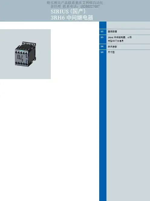
西门子3RH6中间继电器 样本
- 格式:pdf
- 大小:673.23 KB
- 文档页数:10
断相保护热过载继电器 3UA60,3UA61,3UA62GB14048.4,DIN VDE0660 第102部分,IEC 60947-4-1Q/SMS 001,XK06-201 0023防护等级按IEC 60529为IP00级!触指安全性符合GB 4942.2和 DIN VDE0106 第100部分。
调试维修应由专业人员按本使用说明书进行。
安装安装尺寸见图I (单位:mm)a 3UA60:配用附件3UX1424单独安装。
b 3UA60:与3TB50,3TF50接触器组合安装。
c 3UA61:与3TF51接触器组合安装。
d 3UA62:单独安装以及与3TB50接触器组合安装。
e 与3TB50,3TF50接触器组合安装。
f 3UA62:与3TB52,3TF52接触器组合安装。
g 与3TB52,3TF52接触器组合安装。
注:1)至接地部件的最小距离。
适配的接触器见图 II a 连接板宽度 b 直接装配c 当整定电流范围为135~160A ,150~180A 的继电器与3TB52/3TF52 接触器连接时应使用软导线3UX1221作为接线端子间的隔离。
3UA60:与3TB50,3TF50接触器组合安装以及配用3UX1424单独安装。
3UA61:与3TF51接触器组合安装及单独安装。
3UA62:与3TB50,3TB52,3TF52接触器组合安装及单独安装。
允许安装位置见图 IIIa 热过载继电器与接触器组合安装。
b 热过载继电器单独安装。
应避免剧烈的冲击或长时间的振动。
卡装在35mm 标准安装轨(DIN EN50 022)上。
或用2枚螺钉以及平垫圈和弹簧垫圈紧固在平面上。
接线允许的导线截面积见图 IV1) 带接线盒的3UA60,见图Va 2) 不带接线盒的3UA60,见图Vb 接线图见图 VI在单相负载的情况下必须将主回路三相串联起来。
调试参见图 VII①按照负载的额定电流调整刻度盘 ②复位按钮(蓝色)在投入运行前和脱扣后,按一下本按钮使继电器处于待工作状态。
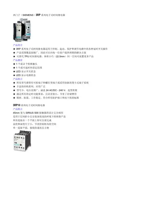
西门子(SIEMENS)3RP系列电子式时间继电器
产品简介
★ 3RP系列电子式时间继电器适用于控制、起动、保护和调节电路中的各种延时开关操作★产品范围覆盖面极广,因此可以向每一位客户提供理想的解决方案
★可替代7PU时间继电器,体积小巧(22.5mm)同一空间可放置更多产品
产品拥有
★ 1个或2个转换触头
★ 1个或可选时间设定范围
★ LED显示开关状态
★ LED显示电源状态
产品特点
★所有型号都带有可拆端子和螺钉型端子或采用创新的笼卡式端子系统
★丰富的结构系列,应用广泛
★型号少,电压范围广,涵盖24 AC/DC - 240 V,选型简便
★满足所有的定时功能要求,且误差很小,节省了存储费用
★精密、防震、工作稳定,符合所有防护接口和抗干扰的标准
3RP10系列电子式时间继电器
产品特点
45mm宽与SIRIUS S00接触器的设计完全相同
是用于层间距小且安装深度浅的环境下的理想产品
所有连接在一个平面上即可全部完成
高度和深度尺寸小,节省控制柜内的空间
单一连接平面,接线快速而且方便。
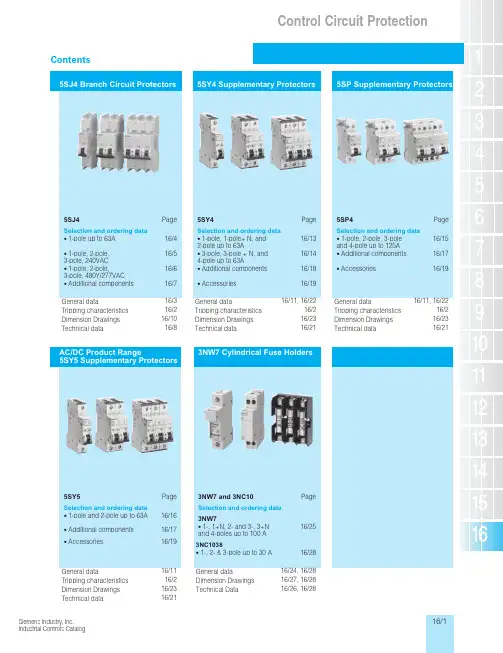
Control Circuit Protection Gener a l D a t aControl Circuit Protection 5SJ Branch Circuit ProtectionControl Circuit Protection 5SJ Branch Circuit ProtectionControl Circuit Protection General Dataand are mounted to the right of them.Control Circuit ProtectionGeneral Data5SJ4...-.HG405SJ4...-.HG425ST3 663-0HG 5ST3 663-1HG 5ST3 663-2HG 5ST3 664-0HG 5ST3 664-1HG 5ST3 664-2HG 5ST3 665-0HG 5ST3 665-1HG 5ST3 665-2HG5ST3 666-0HG 5SJ4...-.HG415ST3 666-1HG5ST3 666-2HGControl Circuit Protection5SY4 Supplementary ProtectionControl Circuit Protection 5SY4 Supplementary ProtectionControl Circuit Protection Supplementary Protection, AC/DC Product RangeControl Circuit Protection Supplementary Protection5Control Circuit Protection Supplementary Protection AccessoriesControl Circuit Protection Supplementary Protection, General DataControl Circuit ProtectionGeneral Data•Meets a wide variety of fuse sizes •Multi-pole configurations•Standard 35 mm (DIN) rail mounting •Housing material meets UL-94-V0, self-extinguishing•Meets UL 512 and CSA C22.2, No. 39 certifications•CE Mark•No tools required for insertion or removal of fuses •Finger safe design•With or without Blown Fuse Indicator •Draw design includes spare fuse holderDepending on the cylindrical* fuse size selected 3NW7 fuse holders are available in 1, 1 + N, 2, 3, 3 + N and 4 pole configu-rations. Fuse sizes include 13/32" x 1-1/2"(Class CC and Midget), 8 mm x 32 mm, 10 mm x 38 mm, 14 mm x 51 mm and 22 x 58 mm.Class CC fuse holders are UL Listed for branch circuit protection according to UL 512 and CSA C22.2, No. 39. They incorporate a rejection feature that only allows Class CC fuses to be used.Midget, 8 mm x 32 mm, 10 mm x 38 mm,14 mm x 51 mm, and 22 x 58 mm fuse holders are UL Recognized (refer to Technical Data for specific fuse holder certifications) as supplementary protectors according to UL 512 and CSA C22.2, No. 39. Supplementary protectors are designed to provide additional protection along with branch circuit protectiondevices.All fuse holders are equipped with either a fuse handle or draw mechanism for easy insertion and removal of cylindrical type fuses. During insertion and removal the fuses are isolated from the power/control circuit. Their compact size requires less space than typical open-type fuse holders and they mount directly onto standard 35 mm mounting rails.Fuse holders for 8 mm x 32 mm, 10 mm x 38 mm fuses in the 1 + N draw design occupy the same mounting space as 1pole designs. This unique design saves space when compared to the typical han-dle type fuse holder which requires two poles.1) Same Mechanical Design - Other Pole Types Not Shown2) LED is “ON” when fuse is blown (open)3) UL 508 busbar available; 5ST3701-0HG, 5ST3705-0HG, 5ST3710-0HG.See page 16/19.EControl Circuit Protection General DataControl Circuit ProtectionSupplementary Protection3NC1038 open fuse holders have been certified in accordance with UL512 and can be used with 13/32" x 1/1-2" (10 x 38 mm) fuses up to 600 V AC, 30 Amperes maximum.•Type M Supplementary Fuse Holder for use with 13/32" x 1-1/2" (10 x 38 mm) Fuses•Typical Supplementary Fuses: Bussmann KTK, FNQ, FNM, BAF and BAN. Includes MIDGET Class Fuses•Ampere Rating: 32A•Voltage Rating: 600 V•Withstand Rating: 10,000 RMS Symmetrical (or interrupting rating of the fuse used, whichever is lower)•Wire Range: 18 to 4 AWG• UL Recognized, UL 512, Fuse Holder•UL Flammability: 94VO•Holder Material:Thermoplastic•Surface Mounted。

真空断路器 3AH3 7.2KV-36KV(2)真空灭弧室图2/5给出了用于3AH3真空断路器中的真空灭弧室的基本结构的剖视图。
根据型号,真空灭弧室(30.)被固定在上支架(20.)。
电弧室(33.)安装在两个陶瓷绝缘子(32.)之间。
静触片(31.)被直接连接在柜上。
动触片(36.)被安装固定在导轨(35.)中的接线端子螺栓(36.1)上。
金属波纹管形成到灭弧室的真空密封连接。
图2/5真空灭弧室安装在3AH3真空断路器中的真空灭弧室被定型核准符合联邦德国的X 射线规则。
它们符合1987年1月8号(联邦法公报第144页)§8规定的X 射线规则的要求和附件Ⅲ第5部分规定的额定瞬间交流电压符合DIN VDE/IDE 标准。
补充说明基本型号的真空断路器包括:带有机械和电气反转的电气操作机械(储能电动机)(M1)合闸线圈(Y9)脱扣分路(Y1)64头带金属孔眼套筒的低压插塞式连接器(X0)辅助开关,6常开+6常闭(S1)“合闸线圈储能”信号的位置开关(S41,S42)断路器分闸信号,信号复位开关(S6,S7)操作次数计数器防止误合闸的闭锁每个3AH3真空断路器也可以装有下面一些设备:接线板(X0)扩展的辅助开关,12常开+12常闭(S1)脱扣分路3AX1101 (Y2)电流互感器操作脱扣3AX1102 (Y4,Y5)电流互感器操作脱扣3AX1104(0.1WS)(Y6)低电压脱扣3AX1103 (Y7)手动电气合闸机械闭锁除标准的脱扣分路外,3AH3真空断路器也可以最多安装两个3AX11型脱扣分路。
在一览表HG11中声明了容许的辅助设备组合和特定的型号。
安装在配电柜或手车上安装供应的3AH3真空断路器是敞开的,可以看到“和闸弹簧脱扣”指示。
在安装3AH3真空断路器之前,先移走运输设备(制动器和定位器)。
根据提供的图纸,面向松开的相间隔板安装。
在将3AH3真空断路器安装进柜中或手车上之前,检查它的额定铭牌数据(避免混乱),比较交货单指明的额定电压与本地可供的电源电压。
DC Motors1GG7, 1GH7, 1HS7 and 1HQ7sSupplement DA 12 × July 2001DC MotorsOrder No.:German:E20002-K4012-A101-A2English:E20002-K4012-A101-A2-7600DA 12DC MotorsDA 12 Supplement1GG7, 1GH7, 1HS7 and 1HQ7July 2001Order No.:German:E86060-K5112-E101-A1English:E86060-K5112-E101-A1-7600DC DrivesPreferred Series up to 500 kW Order No.:German:E20002-K4012-A111-A2English:E20002-K4012-A111-A2-7600DA 12.1SIMOREG Chassis ConvertersOrder No.:German:E20002-K4021-A101-A3English:E20002-K4021-A101-A3-7600DA 21Spare Parts for SIMOREG Chassis Converters Order No.:German:E20002-K4021-A900-A4English:E20002-K4021-A900-A4-7600DA 21 ESIMOREG Converter Cabinet Units Order No.:German:E20002-K4022-A101-A3English:E20002-K4022-A101-A3-7600DA 22Automation and DrivesOrder No.:German:E86060-D4001-A100-B5Eng l ish: E86060-D4001-A110-B4-7600CA 01InternetVisit the Automation and Drives Group in the Internet under the following address:http://www.siemens.de/automationCatalogs of the Automation and Drives Group (A&D)Automation & Drives Catalog Interactive catalogs on CD-ROM•Components for Automation & Drives CA 01•Electrical Installation Technology ET 01Analysis SystemsGas Analysis Equipment for the Process Industry PA 10 Process Analysis, Components for Sample Preparation PA 11 SIPAN Liquid Analysis PA 20Drive SystemsVariable-Speed DrivesDC Motors DA 12 DC Drives Preferred Series up to 500 kW DA 12.1 DC Drives Preferred Series 215 kW to 1500 kW DA 12.2 SIMOREG Chassis Converters DA 21 SIMOREG Converter Cabinet Units DA 22 SIMOVERT PM Modular Converter Systems DA 45 SIEMOSYN Motors DA 48 MICROMASTER 420/440 Inverters DA 51.2 COMBIMASTER 411/MICROMASTER 411DA 51.3 SIMOVERT A Current-Source DC Link Converters DA 62 SIMOVERT MV Medium-Voltage Drives DA 63 MICROMASTER, MIDIMASTER DA 64 Low-Voltage Motors for Variable-Speed Drives DA 65.3 SIMOVERT MASTERDRIVES Vector Control DA 65.10 SIMOVERT MASTERDRIVES Motion Control DA 65.11 SIMADYN D Control System DA 99 Automation Systems for Machine Tools SIMODRIVE NC 60•AC Main Spindle Motors 1FE1, 1PH2, 1PH3, 1PH4,1PH7•AC Servomotors 1FK6, 1FT5, 1FT6•AC Linear motors 1FN1, 1FN3•Converter System SIMODRIVE 611•Converter Systems SIMODRIVE POSMO A/CD/CA/SILow-Voltage Three-Phase-Motors•Project Manual M 10•Squirrel-Cage Motors, Totally Enclosed, Fan-Cooled M 11 Drive and Control Components for Hoisting Equipment HE 1 Automation Systems for Machine ToolsSINUMERIK & SIMODRIVE NC 60 Cables, Connectors and System Components NC Z Human Machine Interface Products/SystemsSIMATIC HMIST 80SIMATIC Industrial Automation SystemsSIMATIC PCS Process Control System ST 45 SIMATIC S5/PC/505 Automation Systems ST 50 Components for Totally Integrated Automation ST 70 Supplementary Components ST 71 SIMATIC PCS 7 Process Control System ST PCS 7 Electrical Installation TechnologyProtective Switching and Fuse SystemsBuilding Management Systems with instabus EIBI 2.1Program Overview Modular Devices I 2.11 STAB Wall-Mounting Distribution Boards I 2.31 SIKUS Floor-Mounting Distribution Boards I 2.328PU Busway System I 2.36Systems Engineering Catalog Power supplies SITOP power KT 10.1 System cables SIMATIC TOP connect KT 10.2 MOBY Identification Systems KT 21 Industrial Microcomputers SICOMP KT 51 Printers and Monitors for Automation and Drives KT 61 Cabinet Packaging System for SIMATIC PCS 7KT 71Industrial Communication and Field Devices IK PILow-Voltage Controls and DistributionLow-Voltage Controlgear, Switchgear and Systems NS K Communication-Capable SIRIUS NET Controlgear,Controlgear, SIGUARD Safety Systems,Control and Signalling Devices, Switchgear,Transformers and DC Power Supplies,Main- and EMERGENCY-STOP Switches,Control Switches, Terminal BlocksSIGNUM Metallic 3SB3Products and Systemsfor Low-Voltage Power DistributionNS PS SENTRON WL NS WLTELEPERM M Process Control SystemAS 235, AS 235H and AS 235K automation systems PLT 111AS 388/TM and AS 488/TM automation systems PLT 112OS 525 operating and monitoring system PLT 122 Operating and monitoring with WinCC/TM PLT 123CS 275 bus system PLT 130Process EngineeringField Instruments for Process AutomationMeasuring Instruments for Pressure,Differential Pressure, Flow, Level and Temperature,Positioners and Liquid MetersFI 01SITRANS LR FI 01 SIWAREX Weighing Systems KT 30 Process Recorders and Accessories MP 20 SIPART, Controllers and Software MP 31Vacuum Pumps/CompressorsOil-Free Vacuum Pumps, Compressors (Blowers),Radial Blowers, Liquid PumpsPVPumpsVacuum Pumps and Compressors, System ELMO-F Cat. Sheets PF Vacuum Pumps and Compressors, System ELMO-G Cat. Sheets PGSIPOS Electric ActuatorsElectric Rotary, Linear and Part-turn Actuators MP 35 Electric Rotary Actuators for Nuclear Plants MP 35.1/.2System SolutionsApplications, Products and Services for Industry SL 01 Automation Solutions in the Plastic Industry•with SIMATIC S7SL 10•with SIMATIC S5ST 58A&D/U3/En 18.04.01Siemens AGAutomation and Drives GroupLarge Drives DivisionP.O. Box 47 43, 90025 NurembergFederal Republic of Germanyhttp://www.siemens.de/automation/ldSiemens Aktiengesellschaft Order No. E86060-K5112-E101-A1-7600sDC Drives DC Motors 1GG7, 1GH7, 1HS7 and 1HQ7 Supplement DA 12 · July 2001DC Motors 1GG7, 1GH7, 1HS7, 1HQ7Supplement DA 12 July 2001IntroductionTechnical FeaturesSelection and Ordering Data Engineering Instructionss32145Dimension DrawingsAppendixAPlease note:The technical data is provided for general information only.When mounting, operating and servicing the equipment, the Instruction Manuals and the information provided on the products themselves must be observed.We reserve the right to revise technical data, selection and ordering data (Order Nos.), accessories and the availability.All of the dimensions in this Catalog are in mm.© Siemens AG 2001Siemens Supplement DA 12 · July 20011/111/2Applications1/4Recommendations for Drive Selection 1/5Overview of Motor Types and Rated Data 1/6DiagramsSiemens Supplement DA 12 · July 2001DC Motors1IntroductionSiemens DC drives distinguish themselves as follows:•Their excellent steady-state and dynamic control response •Their wide range with high control precision•The high efficiency of the complete drive system.The modular DC motors from Siemens are well-proven in combination with driveconverters as variable-speed drives in almost all sectors of industry.This secures competitivestrengths and efficiency for our customers – within Germany and internationally.For example •In mining•In rolling mills•In the printing industry •In the textile and man-made fiber industries •For cranes•In basic industrySIMOREG drive converters.Our DC drives are the optimum solution, no matter which functions have to be fulfilled in drive, power or process engineering.DC MotorsIntroduction1Siemens Supplement DA 12 · July 20011/3Siemens Supplement DA 12 · July 2001DC Motors1IntroductionDetermine the required product profile :Supply voltage DutyDegree of protection Speed range OutputType of construction 3-ph 400, 500 or 690 V ,50/60 Hz1 quadrant/4 quadrant IP ............ n =............rpm P = ............ kWIMPage 2/2 and 3/2 onwardsInstallation conditionsAmbient temperature 40 °C Site altitude1000 mAmbient temperature > 40 °C Site altitude > 1000 m Determining the factors for output and speed changePage 4/2Determine therated armature voltageSupply configuration Duty 3 AC 50/60 Hz 400 V 1Q 3 AC 50/60 Hz 400 V 4Q 3 AC 50/60 Hz 500 V 1Q 3 AC 50/60 Hz 500 V 4Q 3 AC 50/60 Hz 690 V 1Q 3 AC 50/60 Hz 690 V4QRated armature voltage 470 V DC 420 V DC 600 V DC 520 V DC 810 V DC 720 V DCDetermine the Motor Order No.Determine the motor Order No.in accordance with the"Selection and Ordering Data"Pages 3/2 to 3/35Adapt the speed if necessary n = n Nn < n NSpeed adapted via armature control U a = U an · n / n N P = P N · n / n Nn > n NSpeed adapted via field weakening U a = constant P = constantComplete the motor Order No.Options and short codes for special featuresPages 3/39 to 3/41Select the SIMOREG drive converter and the supply componentsFor Order No. of the drive converter and the supply components,see Catalogs DA 21 and DA 22These❝Recommendations for drive selection ❞guide you step-by-step through this CatalogSiemens Supplement DA 12 · July 20011/5DC Motors1Introduction1/6Siemens Supplement DA 12 · July 2001DC Motors1Introduction$1 . . 351%1 . . 352&1 . . 353(1 . . 354)1 . . 355*1 . . 401+1 . . 402,1 . . 403-1 . . 404.1 . . 405/1 . . 45101 . . 45211 . . 45321 . . 45431 . . 455Siemens Supplement DA 12 · July 20012/122/2Standard versions 2/3Mechanical designs 2/3StandardsSiemens Supplement DA 12 · July 2001DC Motors 1GG7, 1GH7, 1HS7, 1HQ72Technical FeaturesTechnical design formotors of Series1G . 7The internally cooled,separately ventilated DC motors 1G . 7 and 1H . 7are fully laminated and compensated. They represent the optimum solution for every drive application as a result of theirmodular design regarding terminal box and separately-driven fan mounting.Standard Type Description Design All IM B3Degree of protection1GG71GH71HS71HQ7IP 23IP 23IP 54IP 54Cooling type1GH71GG71HS71HQ7IC 17IC 06IC W37 A86IC A06 A66Terminal boxPosition Alignment Cable entry All All All RightCable entry from below UndrilledCoolingSep. ventilated Sep. ventilated Closed-circuit coolingClosed-circuit cooling 1GG71GH71HS71HQ7Separately driven fan, top, NDE ExternalAir-to-water heat exchanger, top Air-to-air heat exchanger, top StatorDesign FeaturesAll All RectangularNo housing, fully laminated Duct connection 1GH7On one side, NDE right Paint finish All RAL 7016BearingsAllRoller bearing with regreasing device Vibration severity grade All NShaft end All With keyway acc. to DIN 6885, Sheet 1Balancing All Half-key balancing Field control range All 1.15 x n N Excitation Type VoltageAll All External 310 VWinding type All With compensation winding Number of polesAll4-poleFor design variants and accessories, see Options, Pages 3/39 to 3/41.Siemens Supplement DA 12 · July 2001DC Motors 1GG7, 1GH7, 1HS7, 1HQ72Technical FeaturesPractically spark-freecommutation when fed from drive converters is achieved as a result of the optimum motor design, even in the overload range. This results in extremely long brush lifetimes.Even critical applications can be handled by selecting suitable brush materials.The noise levels of the motors are determined in accordance with DIN EN 21 680 and they lie far below the values permitted according to DIN EN 60 034-9. This is achieved as a result of the mechanical design and by optimizing the magnetic circuit and the separately-driven fan.Noise levels can be provided on request.The motor bearings are provided with regreasing devices.The locating bearing is at the non drive end.The motors comply with all of the relevant standards and specifications, see adjacent table.As a result of the fact that in many countries the national regulations have beencompletely harmonized with the international IEC 60 034-1 recommendation, there are no longer any differences with respect to cooling medium temperatures, insulation classes and maximum temperature rises.Brush materials, commutation Noise levelsBearingsStandards, specifications, requirements TitleDIN/ENIECGeneral specifications for rotating, electrical machinesDIN EN 60 034-1IEC 60 034-1,IEC 60 085Terminal designations and direction of rotation for electrical machines DIN VDE 0530, Part 8IEC 60 034-8Types of construction DIN EN 60 034-7IEC 60 034-7Built-in thermal protection –IEC 60 034-11Cooling types forrotating electrical machinesDIN EN 60 034-6IEC 60 034-6Degrees of protection of rotating electrical machines DIN EN 60 034-5IEC 60034-5Vibration severity ofrotating electrical machines DIN EN 60 034-14IEC 60 034-14Cylindrical shaft ends for electrical machines DIN 748-3IEC 60 072Noise limit values ofrotating electrical machinesDIN EN 60 034-9IEC 60 034-9DC Motors 1GG7, 1GH7, 1HS7, 1HQ7 Technical Features2Siemens Supplement DA 12 · July 2001Siemens Supplement DA 12 · July 20013/13Ordering DataDC Motors 1GG7, 1GH7, 1HS73/2•Rated supply voltage 3-ph. 400 V AC Rated armature voltage 420 V DC,4 quadrant operation3/5•Rated supply voltage 3-ph. 400 V AC Rated armature voltage 470 V DC,1 quadrant operation3/8•Rated supply voltage 3-ph. 500 V AC Rated armature voltage 520 V DC,4 quadrant operation3/11•Rated supply voltage 3-ph. 500 V AC Rated armature voltage 600 V DC,1 quadrant operation3/14•Rated supply voltage 3-ph. 690 V AC Rated armature voltage 720 V DC,4 quadrant operation3/17•Rated supply voltage 3-ph. 690 V AC Rated armature voltage 810 V DC,1 quadrant operation DC Motors 1HQ73/19•Rated supply voltage 3-ph. 400 V AC Rated armature voltage 420 V DC,4 quadrant operation3/22•Rated supply voltage 3-ph. 400 V AC Rated armature voltage 470 V DC,1 quadrant operation3/25•Rated supply voltage 3-ph. 500 V AC Rated armature voltage 520 V DC,4 quadrant operation3/28•Rated supply voltage 3-ph. 500 V AC Rated armature voltage 600 V DC,1 quadrant operation3/31•Rated supply voltage 3-ph. 690 V AC Rated armature voltage 720 V DC,4 quadrant operation3/34•Rated supply voltage 3-ph. 690 V AC Rated armature voltage 810 V DC,1 quadrant operation3/36Supplementary data for selection 3/39Options3Selection and Ordering DataOutputrangeRatedoutputRated speed Order No.Rated torque Max. fieldweakening speedRated current EfficiencyPNnNMnnFmaxINh kW kW rpm Nm rpm A% 197103 1 . . 7 455-5NA . . -1VV11827041259578204138 1 . . 7 454-5NA . . -1VV11411555059580206173 1 . . 7 453-5NA . . -1VV11137069058583208210 1 . . 7 452-5NA . . -1VV1946084058084210254 1 . . 7 451-5NA . . -1VV17895102058085226119 1 . . 7 455-5NB . . -1VV11813547665581230171 1 . . 7 405-5NA . . -1VV11285051064083232158 1 . . 7 454-5NB . . -1VV11402563065083235225 1 . . 7 404-5NA . . -1VV1997068064085236275 1 . . 7 355-5NA . . -1VV1820071064086236238 1 . . 7 452-5NB . . -1VV1947095064086236196 1 . . 7 453-5NB . . -1VV11150078565085238344 1 . . 7 354-5NA . . -1VV16610103063587238288 1 . . 7 451-5NB . . -1VV17890115064087240416 1 . . 7 353-5NA . . -1VV15510125063588240335 1 . . 7 402-5NA . . -1VV16850100064087240284 1 . . 7 403-5NA . . -1VV1810085064586242492 1 . . 7 352-5NA . . -1VV14700148063589242412 1 . . 7 401-5NA . . -1VV15600124064088244580 1 . . 7 351-5NA . . -1VV14000174063590258134 1 . . 7 455-5NC . . -1VV11840053573582262196 1 . . 7 405-5NB . . -1VV11277059071585264178 1 . . 7 454-5NC . . -1VV11416571073084266322 1 . . 7 451-5NC . . -1VV17865129071088266268 1 . . 7 452-5NC . . -1VV19515107071587266256 1 . . 7 404-5NB . . -1VV1993077071587266220 1 . . 7 453-5NC . . -1VV11149588072586268392 1 . . 7 354-5NB . . -1VV16530118071088268314 1 . . 7 355-5NB . . -1VV1815094572586270320 1 . . 7 403-5NB . . -1VV1806096071588272565 1 . . 7 352-5NB . . -1VV14590169071589272475 1 . . 7 353-5NB . . -1VV15470143071589272380 1 . . 7 402-5NB . . -1VV16850114071589274660 1 . . 7 351-5NB . . -1VV13960183071590274468 1 . . 7 401-5NB . . -1VV15600140071589290151 1 . . 7 455-5ND . . -1VV11834060581583298200 1 . . 7 454-5ND . . -1VV11416080082085300224 1 . . 7 405-5NC . . -1VV11279067081086302350 1 . . 7 355-5NC . . -1VV18240105080088304438 1 . . 7 354-5NC . . -1VV16630131080089304364 1 . . 7 451-5ND . . -1VV18000131081088304302 1 . . 7 452-5ND . . -1VV19645119081588304292 1 . . 7 404-5NC . . -1VV1995088080588304248 1 . . 7 453-5ND . . -1VV11166099082587 225250300Separate ventilation usingStand., radially-mounted, sep.-driven fan G GSeparately-mounted, sep.-driven fan G HMounted air-to-water heat exchanger H SExciting voltage180 V1200 V (Order No. + Short Code L5A)9310 V4360 V7Type of constructionIM B30IM B 35 (on request)Field weakeningThe order numbers for themotors are applicable for fieldweakening speeds nFto 1.15 ·nN. For higher field weakeningspeeds, additional short codesare necessary, i.e. "C05"for nF> 1.15 ·nNto 1.7 ·nNand "C06" for nF> 1.7 ·nN.The motors can be operated atrated output PNup to the fieldweakening speed nFmax.Forhigher speeds, the output mustbe reduced.DC Motors 1GG7, 1GH7, 1HS7Siemens Supplement DA 12 · July 20013Selection and Ordering DataSiemens Supplement DA 12 · July 2001DC Motors 1GG7, 1GH7, 1HS7Output range Rated output Rated speed Order No.Rated torque Max. fieldweakening speed Rated current Efficiency P N n N M n n Fmax I N h kWkW rpm Nm rpm A %306530 1 . . 7 353-5NC . . -1VV15510154080090308735 1 . . 7 351-5NC . . -1VV14000181080091308625 1 . . 7 352-5NC . . -1VV14710167080090308432 1 . . 7 402-5NC . . -1VV16800130080589310530 1 . . 7 401-5NC . . -1VV15600160080590310364 1 . . 7 403-5NC . . -1VV18130109081589338177 1 . . 7 455-5NE . . -1VV11824072092086340252 1 . . 7 405-5ND . . -1VV11289076090588344835 1 . . 7 351-5ND . . -1VV13940182089091344500 1 . . 7 354-5ND . . -1VV16570135090090345328 1 . . 7 404-5ND . . -1VV11005098090589345232 1 . . 7 454-5NE . . -1VV11414093092588346605 1 . . 7 353-5ND . . -1VV15460151090090346400 1 . . 7 355-5ND . . -1VV18260117091589348710 1 . . 7 352-5ND . . -1VV14680164090091348484 1 . . 7 402-5ND . . -1VV16850146090091348406 1 . . 7 403-5ND . . -1VV18190122090490350590 1 . . 7 401-5ND . . -1VV15650160090091350418 1 . . 7 451-5NE . . -1VV17995132091090350348 1 . . 7 452-5NE . . -1VV19635120092090350288 1 . . 7 453-5NE . . -1VV111605108092589375675 1 . . 7 401-5NE . . -1VV15300164096092382555 1 . . 7 402-5NE . . -1VV16850146098591382464 1 . . 7 403-5NE . . -1VV17860133099091382288 1 . . 7 405-5NE . . -1VV112670860101088384375 1 . . 7 404-5NE . . -1VV197801130101090394960 1 . . 7 351-5NE . . -1VV139201760101092395462 1 . . 7 355-5NE . . -1VV181701140103090396575 1 . . 7 354-5NE . . -1VV165801310102091398695 1 . . 7 353-5NE . . -1VV154701460102092400820 1 . . 7 352-5NE . . -1VV146601590102092408215 1 . . 7 455-5NF . . -1VV118125790109088415282 1 . . 7 454-5NF . . -1VV114005935109089420505 1 . . 7 451-5NF . . -1VV179601290108092420418 1 . . 7 452-5NF . . -1VV195751180108591420348 1 . . 7 453-5NF . . -1VV11152510501095904341060 1 . . 7 351-5NF . . -1VV139001780110093440640 1 . . 7 354-5NF . . -1VV165701320113092440510 1 . . 7 355-5NF . . -1VV182401150114091440326 1 . . 7 405-5NF . . -1VV112900960115090444770 1 . . 7 353-5NF . . -1VV155101470114092445910 1 . . 7 352-5NF . . -1VV146701600114092445424 1 . . 7 404-5NF . . -1VV11003011401150914487651 . . 7 401-5NF . . -1VV156001570114092325350400Separate ventilation usingStand., radially-mounted, sep.-driven fan G G Separately-mounted, sep.-driven fan G H Mounted air-to-water heat exchangerH SExciting voltage180 V1200 V (Order No. + Short Code L5A )9310 V 4360 V7Type of constructionIM B3IM B 35 (on request)Field weakeningThe order numbers for the motors are applicable for field weakening speeds n F to 1.15 · n N . For higher field weakening speeds, additional short codes are necessary, i.e. "C05" for n F > 1.15 · n N to 1.7 · n N and "C06" for n F > 1.7 · n N .The motors can be operated at rated output P N up to the field weakening speed n Fmax. For higher speeds, the output must be reduced.3OutputrangeRatedoutputRated speed Order No.Rated torque Max. fieldweakening speedRated current EfficiencyPNnNMnnFmaxINhkW kW rpm Nm rpm A% 450625 1 . . 7 402-5NF . . -1VV169001410115092450524 1 . . 7 403-5NF . . -1VV1820012801160914881210 1 . . 7 351-5NG . . -1VV138501*********492870 1 . . 7 401-5NG . . -1VV154001*********495375 1 . . 7 405-5NG . . -1VV112610*********498485 1 . . 7 404-5NG . . -1VV198101170128092500610 1 . . 7 451-5NG . . -1VV178001040127093500600 1 . . 7 403-5NG . . -1VV179701310127092500585 1 . . 7 355-5NG . . -1VV1816011501290925051030 1 . . 7 352-5NG . . -1VV146801*********505880 1 . . 7 353-5NG . . -1VV154701*********505735 1 . . 7 354-5NG . . -1VV165601320128093505715 1 . . 7 402-5NG . . -1VV167501430128093505510 1 . . 7 452-5NG . . -1VV194751150129092505264 1 . . 7 455-5NG . . -1VV118270755133090510424 1 . . 7 453-5NG . . -1VV1115151020131092510344 1 . . 7 454-5NG . . -1VV1141609001320915151370 1 . . 7 351-5NH . . -1VV135901*********5451170 1 . . 7 352-5NH . . -1VV144501650138094550665 1 . . 7 355-5NH . . -1VV179001170140093555995 1 . . 7 353-5NH . . -1VV153401490140093555975 1 . . 7 401-5NH . . -1VV154501550140094555830 1 . . 7 354-5NH . . -1VV164101340141093555420 1 . . 7 405-5NH . . -1VV1126209401420925651600 1 . . 7 351-5NJ . . -1VV133702100142094565800 1 . . 7 402-5NH . . -1VV167501390143093565545 1 . . 7 404-5NH . . -1VV199101120144092570672 1 . . 7 403-5NH . . -1VV1810012501440936051360 1 . . 7 352-5NJ . . -1VV142501880152094605765 1 . . 7 451-5NH . . -1VV175451270153093615640 1 . . 7 452-5NH . . -1VV192051150156093625965 1 . . 7 354-5NJ . . -1VV161701540158093625775 1 . . 7 355-5NJ . . -1VV177001340158093625530 1 . . 7 453-5NH . . -1VV1112601020159593625430 1 . . 7 454-5NH . . -1VV113870895160092625330 1 . . 7 455-5NH . . -1VV1180907501620916301190 1 . . 7 401-5NJ . . -1VV1505017801580946301160 1 . . 7 353-5NJ . . -1VV151901680168094655980 1 . . 7 402-5NJ . . -1VV164001580164094670822 1 . . 7 403-5NJ . . -1VV177801430169094670520 1 . . 7 405-5NJ . . -1VV1123001090170092675670 1 . . 7 404-5NJ . . -1VV196201270171093680880 1 . . 7 451-5NJ . . -1VV173951290170594685730 1 . . 7 452-5NJ . . -1VV189351170172594685610 1 . . 7 453-5NJ . . -1VV1107251060173094695382 1 . . 7 455-5NJ . . -1VV117370770178092705496 1 . . 7 454-5NJ . . -1VV113570905179093 450550600700Separate ventilation usingStand., radially-mounted, sep.-driven fan G GSeparately-mounted, sep.-driven fan G HMounted air-to-water heat exchanger H SExciting voltage180 V1200 V (Order No. + Short Code L5A)9310 V4360 V7Type of constructionField weakeningThe order numbers for themotors are applicable for fieldweakening speeds nFto 1.15 ·nN. For higher field weakeningspeeds, additional short codesare necessary, i.e. "C05"for nF> 1.15 ·nNto 1.7 ·nNand "C06" for nF> 1.7 ·nN.The motors can be operated atrated output PNup to the fieldweakening speed nFmax.Forhigher speeds, the output mustbe reduced.3Output range Rated output Rated speed Order No.Rated torque Max. fieldweakening speed Rated current Efficiency P N n N M n n Fmax I N h kWkW rpm Nm rpm A %226119 1 . . 7 455-5NA . . -1WV11813547659080232158 1 . . 7 454-5NA . . -1WV11402563058583236197 1 . . 7 453-5NA . . -1WV11144079058584238290 1 . . 7 451-5NA . . -1WV17865116057586238240 1 . . 7 452-5NA . . -1WV1951096058585260195 1 . . 7 405-5NA . . -1WV11273059063585260136 1 . . 7 455-5NB . . -1WV11826054566082265180 1 . . 7 454-5NB . . -1WV11406072065585266256 1 . . 7 404-5NA . . -1WV1993077064087268312 1 . . 7 355-5NA . . -1WV1820094064087268326 1 . . 7 451-5NB . . -1WV17850130063588268270 1 . . 7 452-5NB . . -1WV19480108064087268224 1 . . 7 453-5NB . . -1WV11147589565086270390 1 . . 7 354-5NA . . -1WV16610117063589270380 1 . . 7 402-5NA . . -1WV16800114063589270322 1 . . 7 403-5NA . . -1WV1803097064088272555 1 . . 7 352-5NA . . -1WV14680167063590272472 1 . . 7 353-5NA . . -1WV15500142063589272466 1 . . 7 401-5NA . . -1WV15600140063589274655 1 . . 7 351-5NA . . -1WV13990184063590294153 1 . . 7 455-5NC . . -1WV11835061073584300224 1 . . 7 405-5NB . . -1WV11279067072086300202 1 . . 7 454-5NC . . -1WV11418581073086302355 1 . . 7 355-5NB . . -1WV18120107072088302292 1 . . 7 404-5NB . . -1WV1988088071588302365 1 . . 7 451-5NC . . -1WV17900134071089302302 1 . . 7 452-5NC . . -1WV19520121071588302250 1 . . 7 453-5NC . . -1WV111535100072587304445 1 . . 7 354-5NB . . -1WV16520134071589306540 1 . . 7 353-5NB . . -1WV15420155071590306430 1 . . 7 402-5NB . . -1WV16800129071090306362 1 . . 7 403-5NB . . -1WV18070109071589308635 1 . . 7 352-5NB . . -1WV14630169071590308530 1 . . 7 401-5NB . . -1WV15550159071590310745 1 . . 7 351-5NB . . -1WV13970182072091330173 1 . . 7 455-5ND . . -1WV11824069081585338254 1 . . 7 405-5NC . . -1WV11271076080588338228 1 . . 7 454-5ND . . -1WV11409591082087342496 1 . . 7 354-5NC . . -1WV16590138079590342398 1 . . 7 355-5NC . . -1WV18210120080089344330 1 . . 7 404-5NC . . -1WV1995099080589344412 1 . . 7 451-5ND . . -1WV17995131081090344342 1 . . 7 452-5ND . . -1WV19635119081589345600 1 . . 7 353-5NC . . -1WV15490154080091345282 1 . . 7 453-5ND . . -1WV111685106082588346705 1 . . 7 352-5NC . . -1WV14690168080091348830 1 . . 7 351-5NC . . -1WV140001820800923484881 . . 7 402-5NC . . -1WV16800146080590250300Separate ventilation usingStand., radially-mounted, sep.-driven fan G G Separately-mounted, sep.-driven fan G H Mounted air-to-water heat exchangerH SExciting voltage180 V1200 V (Order No. + Short Code L5A )9310 V 4360 V7Type of constructionIM B3Field weakeningThe order numbers for the motors are applicable for field weakening speeds n F to 1.15 · n N . For higher field weakening speeds, additional short codes are necessary, i.e. "C05" for n F > 1.15 · n N to 1.7 · n N and "C06" for n F > 1.7 · n N .The motors can be operated at rated output P N up to the field weakening speed n Fmax. For higher speeds, the output must be reduced.3OutputrangeRatedoutputRated speed Order No.Rated torque Max. fieldweakening speedRated current EfficiencyPNnNMnnFmaxINhkW kW rpm Nm rpm A% 350600 1 . . 7 401-5NC . . -1WV15550160080591350412 1 . . 7 403-5NC . . -1WV18130124081590384202 1 . . 7 455-5NE . . -1WV11815080592087385370 1 . . 7 404-5ND . . -1WV19950111089590385285 1 . . 7 405-5ND . . -1WV11290086090589388940 1 . . 7 351-5ND . . -1WV13940181089092388565 1 . . 7 354-5ND . . -1WV16560136090091390680 1 . . 7 353-5ND . . -1WV15480151090091390264 1 . . 7 454-5NE . . -1WV11411095092089392805 1 . . 7 352-5ND . . -1WV14650164090092392452 1 . . 7 355-5ND . . -1WV18280117091590392545 1 . . 7 402-5ND . . -1WV16850145090091392460 1 . . 7 403-5ND . . -1WV18160133090291394665 1 . . 7 401-5ND . . -1WV15650160090092394472 1 . . 7 451-5NE . . -1WV17955132091091395392 1 . . 7 452-5NE . . -1WV19600120091591396326 1 . . 7 453-5NE . . -1WV111600108092590422760 1 . . 7 401-5NE . . -1WV15300164096092430625 1 . . 7 402-5NE . . -1WV16850146098592432524 1 . . 7 403-5NE . . -1WV17890132099091432424 1 . . 7 404-5NE . . -1WV197401170100091432326 1 . . 7 405-5NE . . -1WV112660*********4421080 1 . . 7 351-5NE . . -1WV139101*********446650 1 . . 7 354-5NE . . -1WV165501310102092446520 1 . . 7 355-5NE . . -1WV181901140103091448785 1 . . 7 353-5NE . . -1WV154501*********450920 1 . . 7 352-5NE . . -1WV146701*********464244 1 . . 7 455-5NF . . -1WV118160*********470318 1 . . 7 454-5NF . . -1WV114025*********472570 1 . . 7 451-5NF . . -1WV179351290108092474392 1 . . 7 453-5NF . . -1WV1115201050109591475472 1 . . 7 452-5NF . . -1WV1961011801090924861200 1 . . 7 351-5NF . . -1WV138701*********495575 1 . . 7 355-5NF . . -1WV182201140115092496720 1 . . 7 354-5NF . . -1WV165801320113092498870 1 . . 7 353-5NF . . -1WV154601*********498368 1 . . 7 405-5NF . . -1WV112920*********5001020 1 . . 7 352-5NF . . -1WV146801*********500478 1 . . 7 404-5NF . . -1WV199901150115091505860 1 . . 7 401-5NF . . -1WV156001*********505705 1 . . 7 402-5NF . . -1WV168501410115092510592 1 . . 7 403-5NF . . -1WV1824012701160925401360 1 . . 7 351-5NG . . -1WV137901*********545980 1 . . 7 401-5NG . . -1WV153001********* 350400500Separate ventilation usingStand., radially-mounted, sep.-driven fan G GSeparately mounted, sep.-driven fan G HMounted air-to-water heat exchanger H SExciting voltage180 V1200 V (Order No. + Short Code L5A)9310 V4360 V7Type of constructionField weakeningThe order numbers for themotors are applicable for fieldweakening speeds nFto 1.15 ·nN. For higher field weakeningspeeds, additional short codesare necessary, i.e. "C05"for nF> 1.15 ·nNto 1.7 ·nNand "C06" for nF> 1.7 ·nN.The motors can be operated atrated output PNup to the fieldweakening speed nFmax.Forhigher speeds, the output mustbe reduced.。
中间继电器接线图及工作原理欧阳光明(2021.03.07)中间继电器(intermediate relay):用于继电保护与自动控制系统中,以增加触点的数量及容量。
它用于在控制电路中传递中间信号。
中间继电器的结构和原理与交流接触器基本相同,与接触器的主要区别在于:接触器的主触头可以通过大电流,而中间继电器的触头只能通过小电流。
所以,它只能用于控制电路中。
它一般是没有主触点的,因为过载能力比较小。
所以它用的全部都是辅助触头,数量比较多。
新国标对中间继电器的定义是K,老国标是KA。
一般是直流电源供电。
少数使用交流供电。
中间继电器原理线圈通电,动铁芯在电磁力作用下动作吸合,带动动触点动作,使常闭触点分开,常开触点闭合;线圈断电,动铁芯在弹簧的作用下带动动触点复位,继电器的工作原理是当某一输入量(如电压、电流、温度、速度、压力等)达到预定数值时,使它动作,以改变控制电路的工作状态,从而实现既定的控制或保护的目的。
在此过程中,继电器主要起了传递信号的作用。
中间继电器组成部分中间继电器就是个继电器,它的原理和交流接触器一样,都是由固定铁芯、动铁芯、弹簧、中间继电器的特点1.整个继电器采用的是模块化结构,它的结构和交流接触器基本相同,只是电磁系统小些,触头组数较多。
继电器的体积小,重量轻,整机动作灵活、可靠,机械寿命为200万次,电气绝缘性能很好,其它的耐振性能、阻燃性能、温度特性、电气性能均达到或超过了标准要求,另外外观新颖,维修也简便2.常见的中间继电器也有主触头和辅助触头,主触头一般有四组,辅助触头有两组。
与接触器相比,它的主触头较小,承载能力低,主要用于传递控制信号。
3.中间继电器作用是用来传递信号或同时控制多个电路,也可直接用它来控制小容量电动机或其他电气执行元件动触点、静触点、线圈、接线端子和外壳组成。
中间继电器的作用一般的电路常分成主电路和控制电路两部分,继电器主要用于控制电路,接触器主要用于主电路;通过继电器可实现用一路控制信号控制另一路或几路信号的功能,完成启动、停止、联动等控制,主要控制对象是接触器;接触器的触头比较大,承载能力强,通过它来实现弱电到强电的控制,控制对象是电器。
开关与保护设备SIRIUS (国产)3RV6/3RV5断路器1/2开关与保护设备电动机保护断路器接触器和接触器组合中间继电器过载继电器软起动器开关与保护设备SIRIUS (国产)3RV6/3RV5断路器1/2介绍√ 有此功能或可使用此附件- 没有此功能或不可使用此附件1) 适用于三相对称负载。
2)使用塑料防护罩附件时为交流 500 V 。
3)对于电动机过载保护,必须使用合适的过载继电器。
开关与保护设备SIRIUS(国产)3RV6/3RV5断路器1/3通用数据操作条件3RV6/3RV5 断路器适用于任何一种气候,应用于封闭空间正常操作环境中(例如无尘埃,无腐蚀性气体或有害气体)。
安装在灰尘和潮湿场所时,需要装配合适的防护罩。
3RV6/3RV5 断路器可以从顶部或底部进线。
断路器允许的环境温度、最大分断能力、脱扣动作电流和其它条件,参考本章具体技术数据和脱扣特性曲线。
3RV6/3RV5 断路器可以在 IT 系统(IT 网络)中使用,但应考虑到在 IT 系统中不同的短路分断能力。
即便是相同额定功率的电动机,由于瞬时峰值电流,其工作电流、起动电流以及电流峰值也是各不相同的。
因此,选择表格中的电动机额定值只能代表指导数据,电动机的实际额定数据和起动数据对选择合适的断路器是非常重要的。
这一原则同样适用于变压器保护用断路器。
应用类别3RV6/3RV5 断路器可用于:•电动机保护•系统保护•起动器组合短路保护•变压器保护•作为主开关和急停开关• IT 系统(IT 网络)•直流回路•防爆应用(ATEX)3RV6/3RV5 断路器为紧凑型限流电动机起动保护断路器,可用于三相感应电动机(交流 400 V 时功率最大至 45 kW)和其他负载(额定电流最大至 100 A)的开合和保护。
规格注释3RV6/3RV5 断路器包括 4 种规格:•S00 规格— 45 mm 宽,最大额定电流 16 A,交流 400 V 时适用感应电动机最大 7.5 kW。
西门子电机样本6ES5,6ES7,6AV,6XV,6EP,6GK,6AG,6RA,6SE,6SL,6SY,6RY,6SN,6FC ,6FX,1PP,2CF,1FT,1FK,1PH,C98043,6DD,6DR,7MH,7ML。
C98043-A1603-L4接电缆-ALLEN BRADLEY SLC500/03,04 - PC (RS232/9 针接头)6XV1801-5DE30 M12-180/M12-180 电源连接电缆,用于ET200 电源,预装配电缆,带M12 连接器和M12 A 编码插座连接器,5 针,0.3m6XV1801-5DE50 M12-180/M12-180 电源连接电缆,用于ET200 电源,预装配电缆,带M12 连接器和M12 A 编码插座连接器,5 针,0.5m6XV1801-5DH10 M12-180/M12-180 电源连接电缆,用于ET200 电源,预装配电缆,带M12 连接器和M12 A 编码插座连接器,5 针,1.0m6XV1801-5DH15 M12-180/M12-180 电源连接电缆,用于ET200 电源,预装配电缆,带M12 连接器和M12 A 编码插座连接器,5 针,1.5m6XV1801-5DH20 M12-180/M12-180 电源连接电缆,用于ET200 电源,预装配电缆,带M12 连接器和M12 A 编码插座连接器,5 针,2.0m6XV1801-5DH30 M12-180/M12-180 电源连接电缆,用于ET200 电源,预装配电缆,带M12 连接器和M12 A 编码插座连接器,5 针,3.0m6XV1801-5DH50 M12-180/M12-180 电源连接电缆,用于ET200 电源,预装配电缆,带M12 连接器和M12 A 编码插座连接器,5 针,5.0m6XV1801-5DN10 M12-180/M12-180 电源连接电缆,用于ET200 电源,预装配电缆,带M12 连接器和M12 A 编码插座连接器,5 针,10.0m6XV1801-5DN15 M12-180/M12-180 电源连接电缆,用于ET200 电源,预装配电缆,带M12 连接器和M12 A 编码插座连接器,5 针,15.0m6XV1812-8A SIMATIC NET 电源电缆, 2 线制电源电缆, LITZ 导线, 2 x 0.75 平方毫米, 拖缆,最大长度: 2000m, 最小订购长度: 20m, 按米销售6XV1820-5AH10 SIMATIC NET, 光纤标准电缆,C98043-A1603-L46XV1821-0BN15 SIMATIC NET, PROFIBUS 塑料光纤,标准光缆, 带有4 个BFOC 连接器,L = 15m6XV1821-0BN20 SIMATIC NET, PROFIBUS 塑料光纤,标准光缆, 带有4 个BFOC 连接器,L = 20m6XV1821-0BN25 SIMATIC NET, PROFIBUS 塑料光纤,标准光缆, 带有4 个BFOC 连接器,L = 25m6XV1821-0BN30 SIMATIC NET, PROFIBUS 塑料光纤,标准光缆, 带有4 个BFOC 连接器,L = 30m6XV1821-0BN50 SIMATIC NET, PROFIBUS 塑料光纤,标准光缆, 带有4 个BFOC 连接器,L = 50m6XV1821-0BN65 SIMATIC NET, PROFIBUS 塑料光纤,标准光缆, 带有4 个BFOC 连接器,L = 65m6XV1821-0BN80 SIMATIC NET, PROFIBUS 塑料光纤,标准光缆, 带有4 个BFOC 连接器,L = 80m6XV1821-1BN75 SIMATIC NET, PROFIBUS PCF 光纤,带有4 个BFOC 连接器,L = 75m6XV1821-1BT10 SIMATIC NET, PROFIBUS PCF 光纤,带有4 个BFOC 连接器,L = 100m6XV1821-1BT15 SIMATIC NET, PROFIBUS PCF 光纤,带有4 个BFOC 连接器,L = 150m6XV1821-1BT20 SIMATIC NET, PROFIBUS PCF 光纤,带有4 个BFOC 连接器,L = 200m6XV1821-1BT25 SIMATIC NET, PROFIBUS PCF 光纤,带有4 个BFOC 连接器,L = 250m6XV1821-1BT30 SIMATIC NET, PROFIBUS PCF 光纤,带有4 个BFOC 连接器,L = 300mC98043-A1603-L4户内安装的玻璃光纤电缆, 按米销售, 最大长度: 2000m, 最小订购长度: 20 m6XV1820-7BH05 SIMATIC NET, 户内用纤维光缆, 无卤素, 抗踩踏, 阻燃, 用于户内安装的玻璃光纤电缆, 预装有4 个BFOC 接头, 长度0.5m6XV1820-7BH10 SIMATIC NET, 户内用纤维光缆, 无卤素, 抗踩踏, 阻燃, 用于户内安装的玻璃光纤电缆, 预装有4 个BFOC 接头, L = 1m6XV1820-7BH20 SIMATIC NET, 户内用纤维光缆, 无卤素, 抗踩踏, 阻燃, 用于户内安装的玻璃光纤电缆, 预装有4 个BFOC 接头, L = 2m6XV1820-7BH30 SIMATIC NET, 户内用纤维光缆, 无卤素, 抗踩踏, 阻燃, 用于户内安装的玻璃光纤电缆, 预装有4 个BFOC 接头, L = 3m6XV1820-7BH50 SIMATIC NET, 户内用纤维光缆, 无卤素, 抗踩踏, 阻燃, 用于户内安装的玻璃光纤电缆, 预装有4 个BFOC 接头, L = 5m6XV1820-7BN10 SIMATIC NET, 户内用纤维光缆, 无卤素, 抗踩踏, 阻燃, 用于户内安装的玻璃光纤电缆, 预装有4 个BFOC 接头, L = 10m6XV1820-7BN15 SIMATIC NET, 户内用纤维光缆, 无卤素, 抗踩踏, 阻燃, 用于户内安装的玻璃光纤电缆, 预装有4 个BFOC 接头, L = 15 m6XV1820-7BN20 SIMATIC NET, 户内用纤维光缆, 无卤素, 抗踩踏, 阻燃, 用于户内安装的玻璃光纤电缆, 预装有4 个BFOC 接头, L = 20 m6XV1820-7BN25 SIMATIC NET, 户内用纤维光缆, 无卤素, 抗踩踏, 阻燃, 用于户内安装的玻璃光纤电缆, 预装有4 个BFOC 接头, L = 25 m6XV1820-7BN50 SIMATIC NET, 户内用纤维光缆, 无卤素, 抗踩踏, 阻燃, 用于户内安装的玻璃光纤电缆, 预装有4 个BFOC 接头, L = 50 m6XV1820-7BN75 SIMATIC NET, 户内用纤维光缆, 无卤素, 抗踩踏, 阻燃, 用于户内安装的玻璃光纤电缆, 预装有4 个BFOC 接头, L = 75 m6XV1820-7BT10 SIMATIC NET, 户内用纤维光缆, 无卤素, 抗踩踏, 阻燃, 用于户内安装的玻璃光纤电缆, 预装有4 个BFOC 接头, L = 100 m6XV1821-0AH10 SIMATIC NET, PROFIBUS 塑C98043-A1603-L4。
8■Overview SIRIUS 3UG46 15 monitoring relaySolid-state line monitoring relays provide maximum protection for mobile machines and plants or for unstable networks. Net-work and voltage faults can be detected early and rectified be-fore far greater damage ensues.Depending on the version, the relays monitor phase sequence, phase failure with and without N conductor monitoring, phase asymetry, undervoltage or overvoltage.Phase asymetry is evaluated as the difference between the greatest and the smallest phase voltage relative to the greatest phase voltage. Undervoltage or overvoltage exists when at least one phase voltage deviates by 20 % from the set rated system voltage or the directly set limit values are overshot or undershot. The rms value of the voltage is measured.With the 3UG46 17 or 3UG46 18 relay, a wrong direction of rota-tion can also be corrected automatically.■Benefits•Can be used without auxiliary voltage in any network from 160 to 600 V AC worldwide thanks to wide voltage range •Variably adjustable to overvoltage, undervoltage or range monitoring•Freely configurable delay times and RESET response •Width 22.5 mm•Permanent display of ACTUAL value and network fault type on the digital versions•Automatic correction of the direction of rotation by distinguish-ing between power system faults and wrong phase sequence •All versions with removable terminals•All versions with screw terminals or alternatively with innova-tive spring-type terminals■ApplicationThe relays are used above all for mobile equipment,e.g. air conditioning compressors, refrigerating containers, building site compressors and cranes.■Technical specifications3UG45 11 monitoring relaysThe 3UG45 11 phase sequenced relay monitors the phase se-quence in a three-phase network. No adjustments are required for operation. The device has an internal power supply and works using the closed-circuit principle. If the phase sequence at the terminals L1-L2-L3 is correct, the output relay picks up af-ter the delay time has elapsed and the LED is lit. If the phase se-quence is wrong, the output relay remains in its rest position.Note:When one phase fails, connected loads (motor windings, lamps, transformers, coils, etc.) create a feedback voltage at the termi-nal of the failed phase due to the network coupling. Because the 3UG45 11 relays are not resistant to voltage feedback, such a phase failure is not detected. Should this be required, then the 3UG45 12 monitoring relay must be used.Correct phase sequenceWrong phase sequenceFunction ApplicationPhase sequence •Direction of rotation of the drive Phase failure•A fuse has tripped•Failure of the control supply voltage •Broken cablePhase asymmetry•Overheating of the motor due to asymmetrical voltage•Detection of asymmetrically loaded networksUndervoltage•Increased current on a motor with correspond-ing overheating•Unintentional resetting of a device•Network collapse, particularly with battery powerOvervoltage•Protection of a plant against destruction due to overvoltage8 3UG45 12 monitoring relaysThe 3UG45 12 line monitoring relay monitors three-phase net-works with regard to phase sequence, phase failure and phaseunbalance of 10 %. Thanks to a special measuring method, aphase failure is reliably detected in spite of the wide voltagerange from 160 to 690 V and feedback through the load of up to90 %. The device has an internal power supply and works usingthe closed-circuit principle. No adjustments are required. Whenthe mains voltage is switched on, the green LED is lit. If thephase sequence at the terminals L1-L2-L3 is correct, the outputrelay picks up. If the phase sequence is wrong, the red LEDflashes and the output relay remains in its rest position. If aphase fails, the red LED is permanently lit and the output relaydrops.Note:The red LED is a fault diagnostic indicator and does not show thecurrent relay status. The 3UG45 12 monitoring relay is suitablefor line frequencies of 50/60 Hz.Phase failureWrong phase sequence3UG45 13 monitoring relaysThe 3UG45 13 line monitoring relay monitors three-phase net-works with regard to phase sequence, phase failure, phaseasymetry and undervoltage of 20 %. The device has an internalpower supply and works using the closed-circuit principle. Thehysteresis is 5 %. The integrated response delay time is adjust-able from 0 to 20 s and responds to undervoltage. If the directionis incorrect, the device switches off immediately. Thanks to aspecial measuring method, a phase failure is reliably detected inspite of the wide voltage range from 160 to 690 V and feedbackthrough the load of up to 80%. When the mains voltage isswitched on, the green LED is lit. If the phase sequence at theterminals L1-L2-L3 is correct, the output relay picks up. If thephase sequence is wrong, the red LED flashes and the outputrelay remains in its rest position. If a phase fails, the red LED ispermanently lit and the output relay drops.Note:The red LED is a fault diagnostic indicator and does not show thecurrent relay status. The 3UG45 13 monitoring relay is suitablefor line frequencies of 50/60 Hz.Phase failure and undervoltageWrong phase sequence8/6383UG46 14 monitoring relaysThe 3UG46 14 line monitoring relay has a wide voltage rangeand an internal power supply. The device is equipped with a dis-play and is parameterized using three buttons. It monitors three-phase networks with regard to phase asymetry from 5 to 20%,phase failure, undervoltage and phase sequence. The hystere-sis is adjustable from 1 to 20 V. In addition the device has a re-sponse delay and ON-delay from 0 to 20 s in each case. The in-tegrated response delay time responds to phase asymetry andundervoltage. If the direction is incorrect, the device switches offimmediately. Thanks to a special measuring method, a phasefailure is reliably detected in spite of the wide voltage range from160 to 690 V and feedback through the load of up to 80%.The 3UG46 14 monitoring relay can be operated on the basis ofeither the open-circuit or closed-circuit principle and with man-ual or auto RESET.With the closed-circuit principle selected3UG46 15/ 3UG46 16 monitoring relaysThe 3UG46 15/3UG46 16 line monitoring relay has a wide volt-age range and an internal power supply. The device is equippedwith a display and is parameterized using three buttons. The3UG46 15 device monitors three-phase networks with regard tophase failure, undervoltage, overvoltage and phase sequence.The 3UG46 16 monitoring relay monitors the neutral conductoras well. The hysteresis is adjustable from 1 to 20 V. In additionthe device has two separately adjustable delay times for over-voltage and undervoltage from 0 to 20 s in each case. If the di-rection is incorrect, the device switches off immediately. Thanksto a special measuring method, a phase failure is reliably de-tected in spite of the wide voltage range from 160 to 690 V andfeedback through the load of up to 80%.The 3UG46 15/ 3UG46 16 monitoring relay can be operated onthe basis of either the open-circuit or closed-circuit principle andwith manual or auto RESET.With the closed-circuit principle selected8/648 3UG46 17/ 3UG46 18 monitoring relaysThe 3UG46 17/ 3UG46 18 line monitoring relay has an internalpower supply and can automatically correct a wrong direction ofrotation. Thanks to a special measuring method, a phase failureis reliably detected in spite of the wide voltage range from160 to 690 V AC and feedback through the load of up to 80%.The device is equipped with a display and is parameterized us-ing three buttons. The 3UG46 17 line monitoring relay monitorsthree-phase networks with regard to phase sequence, phasefailure, phase unbalance, undervoltage and overvoltage. The3UG46 18 monitoring relay monitors the neutral conductor aswell. The hysteresis is adjustable from 1 to 20 V. In addition thedevice has delay times from 0 to 20 s in each case for overvolt-age, undervoltage, phase failure and phase unbalance. The3UG46 17/ 3UG46 18 monitoring relay can be operated on thebasis of either the open-circuit or closed-circuit principle andwith manual or auto RESET. The one changeover contact is usedfor warning or disconnection in the event of power system faults(voltage, unbalance), the other responds only to a wrong phasesequence. In conjunction with a contactor reversing assembly itis thus possible to change the direction automatically.With the closed-circuit principle selectedCircuit diagramsType3UG45 11 ... 3UG45 13, 3UG46 14 ... 3UG46 18General dataRated insulation voltage U iPollution degree 3Overvoltage category III acc. to EN 60664-1V690Rated impulse withstand voltage kV6Control circuitLoad capacity of the output relay•Conventional thermal current I th A5Rated operational current I e at•AC-15/24 ... 400 V A3•DC-13/24 V A1•DC-13/125 V A0.2•DC-13/250 V A0.1Minimum contact load at 17 V DC mA5Electrical endurance AC-15Million oper-ating cycles0.1Mechanical endurance Million oper-ating cycles103UG45 11-.A,3UG45 12-.A3UG45 11-.B, 3UG45 12-.B,3UG45 13, 3UG46 14,3UG46 15, 3UG46 173UG46 16,3UG46 18Note:It is not necessary to protect themeasuring circuit for device pro-tection. The protective device forline protection depends on thecross-section used.8/658/66*You can order this quantity or a multiple thereof.8■Selection and ordering dataPU (UNIT, SET, M)= 1PS*= 1 unit PG = 101✓ Function available -- Function not available1)Absolute limit values.2)1 CO contact each and 1 tripping delay time each for U min and U max .3)1 CO contact each for power system fault and phase sequence correction.For accessories, see page 8/90.Hysteresis Over-ON-delay Trippingdelay Rated control Screw terminalsDTSpring-type 3UG45 11-2BP203UG45 11-1AP203UG46 15-1CR203UG46 16-1CR203UG45 12-2BR203UG46 17-1CR203UG46 18-1CR208■OverviewSIRIUS 3UG46 31 monitoring relayThe relays monitor single-phase AC voltages (rms value) andDC voltages against the set threshold value for overshoot andundershoot. The devices differ with regard to their power supply(internal or external).■Benefits•Versions with wide voltage supply range•Variably adjustable to overvoltage, undervoltage or rangemonitoring•Freely configurable delay times and RESET response•Width 22.5 mm•Display of ACTUAL value and status messages•All versions with removable terminals•All versions with screw terminals or alternatively with innova-tive spring-type terminals■Application•Protection of a plant against destruction due to overvoltage•Switch-on of a plant at a defined voltage and higher•Protection against overloaded control supply voltages,particularly with battery power•Threshold switch for analog signals from 0.1 to 10V■Technical specifications3UG46 33 monitoring relaysThe 3UG46 33 voltage monitoring relay has an internal powersupply and performs overshoot, undershoot or range monitoringof the voltage depending on how it is parameterized. The deviceis equipped with a display and is parameterized using threebuttons.The operating and measuring range extends from 17 to275V AC/DC. The threshold values for overshoot or undershootcan be freely configured within this range. If one of these thresh-old values is reached, the output relay responds according tothe set principle of operation as soon as the tripping delay timehas elapsed. This delay time U Del can be set from 0.1 to 20s likethe ON-delay time on Del.The hysteresis is adjustable from 0.1 to 150V. The device can beoperated on the basis of either the open-circuit or closed-circuitprinciple and with manual or auto RESET. One output change-over contact is available as signaling contact.With the closed-circuit principle selectedOvervoltageUndervoltageRange monitoring8/6783UG46 31/ 3UG46 32 monitoring relaysThe 3UG46 31/3UG46 32 voltage monitoring relay is suppliedwith an auxiliary voltage of 24 V AC/DC or 24 to 240V AC/DCand performs overshoot, undershoot or range monitoring of thevoltage depending on how it is parameterized. The device isequipped with a display and is parameterized using threebuttons.The measuring range extends from 0.1 to 60 V or 10 to600V AC/DC. The threshold values for overshoot or undershootcan be freely configured within this range. If one of these thresh-old values is reached, the output relay responds according tothe set principle of operation as soon as the delay time haselapsed. This delay time U Del can be set from 0.1 to 20 s.The hysteresis can be set from 0.1 to 30 V or 0.1 to 300 V. Thedevice can be operated on the basis of either the open-circuit orclosed-circuit principle and with manual or auto RESET. One out-put changeover contact is available as signaling contact.With the closed-circuit principle selectedOvervoltageUndervoltageRange monitoringCircuit diagrams3UG46 313UG46 323UG46 33 General dataRated insulation voltage U iPollution degree 3Overvoltage category III acc. to EN 60664-1V690Rated impulse withstand voltage U imp kV6Measuring circuitPermissible measuring range single-phase AC/DC voltage V0.1 ... 6810 ... 65017 (275)Setting range single-phase voltage V0.1 ... 6010 ... 60017 (275)Measuring frequency Hz40 (500)Control circuitLoad capacity of the output relay•Conventional thermal current I th A5Rated operational current I e at•AC-15/24 ... 400 V A3•DC-13/24 V A1•DC-13/125 V A0.2•DC-13/250 V A0.1Minimum contact load at 17 V DC mA53UG46 31-.AA30,3UG46 32-.AA303UG46 31-.AW30,3UG46 32-.AW303UG46 33Note:It is not necessary to protect themeasuring circuit for deviceprotection. The protective devicefor line protection depends on thecross-section used.8/688/69*You can order this quantity or a multiple thereof.8■Selection and ordering data•Digitally adjustable, with illuminated LC display •Auto or manual RESET•Open or closed-circuit principle •1 CO contactPU (UNIT, SET, M)= 1PS*= 1 unit PG = 101Absolute limit values.For accessories, see page 8/90.Measuring rangeHysteresis3UG46 31-1AA303UG46 33-2AL30。