海大-EDA实验1参考答案
- 格式:docx
- 大小:14.54 KB
- 文档页数:12
红外多路遥控系统单片机红外发射红外接收本文介绍了红外多路遥控系统。
红外多路遥控系统可实现16路的红外开关控制。
以码分制多通道红外遥控为设计的基本思路。
通过键盘及代码生成电路、编码、脉冲调制振荡和红外发射构成红外发射电路。
通过红外接收,解码以及由单片机控制的医码控制电路组成红外接收电路。
1.前言1.1序言随着电子技术的飞速发展,尤其是跨入2000年后,红外技术得到了迅猛发展。
红外遥控已渗透到国民经济的各行各业和人们日常生活的方方面面,在工业自动化、生产控制过程、采集和处理、通信、红外制导、激光武器、电子对抗、环境监测、红外育种安全防范、家用电器控制及日常生活各个方面都得到了广泛的应用。
1.2国内外研究概况目前国内外都在进行红外的研究开发,已取得了相当不错的成绩。
红外技术的研究开发是自动化控制的主要方向。
它的研究针对国民经济的各行各业和人们日常生活的方方面面,在工业自动化、生产控制过程、采集和处理、通信、红外制导、激光武器、电子对抗、环境监测、红外育种安全防范、家用电器控制及日常生活各个方面都在进行红外研究开发和控制。
1.3主要工作概述针对国内外的发展情况,可见红外遥控系统是我国未来智能化发展方向。
本课题要设计的红外多路遥控系统,主要红外发射和红外接收这两部分,本设计依托市面上常见的红外发射和红外接收元器件,使设计具有传输距离一般、硬件简单、安装方便、价格便宜的优点。
本文所介绍的红外多路遥控系统,是采用码分制多通道红外遥控系统装置。
早期的码分制的脉冲指令编码多采用分离元器件及小规模数字集成电路,编码、译码电路弄得很复杂,可靠性也差。
但随着大规模数字集成技术的发展和日趋成熟,各种大规模专用集成编、译码集成器件的层出不穷,使外围元器件很少,电路简单,功能完善。
2.系统总体方案设计2.1方案比较方案一:采用频分制多通道红外遥控发射和接收系统。
频分制的频率编码一般采用频道编码开关,通过改变振荡电路的参数来改变振荡电路的振荡参数和频率。
eda课程设计题目答案一、教学目标本课程的教学目标是使学生掌握eda的基本概念、原理和应用方法,培养学生分析问题和解决问题的能力,提高学生的创新意识和实践能力。
具体来说,知识目标包括:了解eda的基本概念、原理和流程;掌握常见的eda工具和软件的使用方法;了解eda在电子设计中的应用领域。
技能目标包括:能够运用eda工具进行基本的电路设计和仿真;能够根据设计需求选择合适的eda工具和软件;能够对设计结果进行分析和评估。
情感态度价值观目标包括:培养学生对eda技术的兴趣和热情;培养学生勇于探索、创新和合作的精神;培养学生关注社会、关注科技发展的意识。
二、教学内容本课程的教学内容主要包括eda的基本概念、原理和应用方法。
具体安排如下:第1章:eda概述,介绍eda的定义、发展历程和应用领域;第2章:eda工具和软件,介绍常见的eda工具和软件的使用方法;第3章:电路设计,介绍电路设计的基本原理和方法;第4章:仿真与验证,介绍仿真与验证的基本原理和方法;第5章:eda应用案例,介绍eda在实际项目中的应用案例。
三、教学方法为了实现本课程的教学目标,我们将采用多种教学方法,包括讲授法、讨论法、案例分析法和实验法等。
具体安排如下:第1章:采用讲授法,介绍eda的基本概念和原理;第2章:采用讨论法,引导学生探讨eda工具和软件的使用方法;第3章:采用案例分析法,分析实际电路设计案例;第4章:采用实验法,让学生动手进行电路设计和仿真;第5章:采用讲授法和讨论法,总结本课程的主要内容和知识点。
四、教学资源为了支持本课程的教学内容和教学方法的实施,我们将准备以下教学资源:教材:《eda技术与应用》;参考书:《电子设计自动化原理与应用》;多媒体资料:教学PPT、视频教程等;实验设备:计算机、eda工具软件、电路实验板等。
以上教学资源将有助于丰富学生的学习体验,提高学生的学习效果。
五、教学评估本课程的教学评估将采用多元化的评估方式,以全面、客观、公正地评价学生的学习成果。
1.功能仿真和时序仿真有何不同?为什么?答:EDA 中功能仿真是纯理论的仿真,功能仿真不考虑信号传送过程中的延迟。
仿真结果可以和我们的真值表对应起来。
而时序仿真则要考虑信号传送过程中的延迟,有可能出现竞争冒险等。
时序仿真比较接近实际。
由图(2)(3)中可知时序仿真中的波形有一小段时间比功能仿真中的波形多了一个BCD码--13。
因为功能仿真只是考虑元件的理想功能,而时序仿真考虑到实际元器件的信号延时、输入/输出时间的延时、触发器的建立/保持时间、寄存器的性能等等1,什么是同步清零和异步清零?同步清零就是把清零信号和时钟信号与或者与非处理后输入到清零端,异步清零的清零信号直接输入到清零端。
同步清零可以保证状态在时钟的有效期内不会改变。
就是说,同步清零要与时钟同步触发,而异步清零就不关心时钟上升沿是否到来。
2,BCD计数器和一般二进制计数器有何差别?用4位二进制数来表示1位十进制数中的0~9这10个数码,简称BCD码。
称BCD码或二-十进制代码,亦称二进码十进数。
是一种二进制的数字编码形式,用二进制编码的十进制代码。
由于十进制数共有0、1、2、……、9十个数码,因此,至少需要4位二进制码来表示1位十进制数。
4位二进制码共有2^4=16种码组,在这16种代码中,可以任选10种来表示10个十进制数码,共有N=16!/(16-10)!约等于2.9乘以10的10次方种方案。
二进制计数器是数字系统中用得较多的基本逻辑器件。
它不仅能记录输入时钟脉冲的个数,还可以实现分频、定时、产生节拍脉冲和脉冲序列等。
例如,计算机中的时序发生器、分频器、指令计数器等都要使用计数器。
计数器的种类很多。
按时钟脉冲输入方式的不同,可分为同步计数器和异步计数器;按进位体制的不同,可分为二进制计数器和非二进制计数器;按计数过程中数字增减趋势的不同,可分为加计数器、减计数器和可逆计数器3.键盘为什么要防抖动?如何防抖动?主要目的是为了提高按键输入可靠性,由于机械触点的弹性振动,按键在按下时不会马上稳定地接通而在弹起时也不能一下子完全地断开,因而在按键闭合和断开的瞬间均会出现一连串的抖动,这称为按键的抖动干扰。
EDA设计(I)实验报告摘要EDA技术是指以计算机为工作平台,利用EDA仿真软件从概念、算法、协议等开始设计电子系统,将电子产品从电路设计、性能分析到IC版图或PCB版图的设计等大量工作都通过计算机完成。
EDA技术的出现,极大地提高了电路设计的效率和可操作性,减轻了设计者的劳动强度。
目前EDA的概念已渗透到机械、电子、通信、航空航天、化工、矿产、生物、医学、军事等各个领域。
本次试验利用Multisim12.0软件进行仿真,结合大二上学期所学模拟电子线路知识,分别完成了单级放大电路设计、差动放大电路设计、负反馈放大电路设计及阶梯波发生器设计等四个实验的设计,仿真及误差分析,进一步巩固了模拟电子线路知识。
关键词EDA技术Multisim12.0 模拟电子线路仿真分析目录实验一单级放大电路设计 (1)一、实验要求 (1)二、实验步骤 (1)三、数据分析与实验思考 (10)四、实验小结 (11)实验二差动放大电路设计 (12)一、实验要求 (12)二、实验步骤 (12)三、实验思考与改进 (23)实验三负反馈放大电路的设计 (24)一、实验要求 (24)二、实验步骤 (24)三、实验总结 (32)设计四阶梯波发生器设计 (33)一、实验要求 (33)二、实验步骤 (33)三、回答问题 (41)四、改进电路 (42)_______________________________________________________________________________________________________________________________________________________实验一单级放大电路设计一、实验要求1、设计一个分压偏置的单管电压放大电路,要求信号源频率20kHz,峰值5mV ,负载电阻1.8kΩ,电压增益大于50。
2、调节电路静态工作点,观察电路出现饱和失真和截止失真的输出信号波形,并测试对应的静态工作点值。
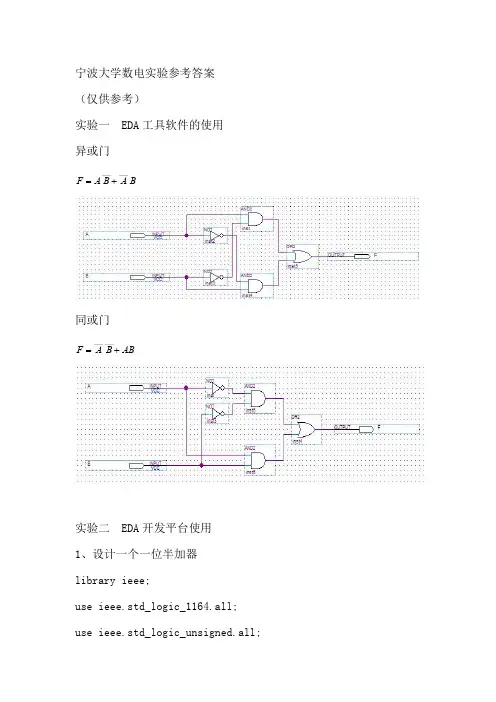
宁波大学数电实验参考答案(仅供参考)实验一EDA 工具软件的使用异或门B A B A F ______+=同或门AB B A F +=______实验二EDA 开发平台使用1、设计一个一位半加器library ieee;use ieee.std_logic_1164.all;use ieee.std_logic_unsigned.all;entity banjia isport(a,b:in std_logic;s,c:out std_logic);end banjia;architecture behav of banjia is begins<=a xor b;c<=a and b;end behav;2、二进制全加器library ieee;use ieee.std_logic_1164.all;use ieee.std_logic_unsigned.all;entity fadder isport(a:in std_logic;b:in std_logic;c:in std_logic;s:out std_logic;d:out std_logic);end fadder;architecture behav of fadder isbegins<=a xor b xor c;d<=(a and b)or(a and c)or(b and c);end behav;实验五MSI组合电路的HDL设计1、3—8译码器library ieee;use ieee.std_logic_1164.all;use ieee.std_logic_unsigned.all;entity decoder38isport(x:in std_logic_vector(2downto0);y:out std_logic_vector(7downto0) );end decoder38;architecture behav of decoder38isbeginprocess(x)begincase x iswhen"000"=>y<="00000001"; when"001"=>y<="00000010"; when"010"=>y<="00000100"; when"011"=>y<="00001000"; when"100"=>y<="00010000"; when"101"=>y<="00100000"; when"110"=>y<="01000000"; when"111"=>y<="10000000";when others=>null;end case;end process;end behav;2、显示译码器library ieee;use ieee.std_logic_1164.all;use ieee.std_logic_unsigned.all;entity xianshi isport(a:in std_logic_vector(3downto0);b:out std_logic_vector(6downto0) );end xianshi;architecture behav of xianshi isbeginprocess(a)begincase a iswhen"0000"=>b<="0111111";when"0001"=>b<="0000110";when"0010"=>b<="1011011";when"0011"=>b<="1001111";when"0100"=>b<="1100110"; when"0101"=>b<="1101101"; when"0110"=>b<="1111101"; when"0111"=>b<="0000111"; when"1000"=>b<="1111111"; when"1001"=>b<="1101111"; when"1010"=>b<="1110111"; when"1011"=>b<="1111100"; when"1100"=>b<="0111001"; when"1101"=>b<="1011110"; when"1110"=>b<="1111001"; when"1111"=>b<="1110001";when others=>null;end case;end process;end behav;3、数据选择器library ieee;use ieee.std_logic_1164.all;use ieee.std_logic_unsigned.all;entity select41isport(x:in std_logic_vector(1downto0);a:in std_logic;b:in std_logic;c:in std_logic;d:in std_logic;y:out std_logic);end select41;architecture behav of select41isbeginprocess(x)begincase x iswhen"00"=>y<=a;when"01"=>y<=b;when"10"=>y<=c;when"11"=>y<=d;when others=>null;end case;end process;end behav;实验六用MSI设计组合逻辑电路1、输血血型验证2、单“1”检测器实验七集成触发器及使用1、用触发器设计四位异步计数器2、用触发器设计四位移位寄存器实验八时序电路的HDL设计1、模可变计数器library ieee;use ieee.std_logic_1164.all;use ieee.std_logic_unsigned.all;entity adder isport(clk:in std_logic;E:in std_logic;--E='1'则使能G:in std_logic;--G='1'为加,'0'为减M:in std_logic_vector(1downto0);--模选择y:out std_logic_vector(3downto0)--结果);end adder;architecture behav of adder issignal q:std_logic_vector(3downto0);beginprocess(E,G,clk)beginif E='0'thenq<=(others=>'0');elsif clk'event and clk='1'thenif G='1'thenif M="00"thenif q<"0001"thenq<=q+1;else q<=(others=>'0');end if;elsif M="01"thenif q<"0111"thenq<=q+1;else q<=(others=>'0');end if;elsif M="10"thenif q<"1001"thenq<=q+1;else q<=(others=>'0');end if;elsif M="11"thenq<=q+1;end if;elsif G='0'thenif M="00"thenif q>"1110"thenq<=q-1;elsif q="0000"thenq<="1111";else q<="1111";end if;elsif M="01"thenif q>"1000"thenq<=q-1;elsif q="0000"thenq<="1111";else q<="1111";end if;elsif M="10"thenif q>"0110"thenq<=q-1;elsif q="0000"thenq<="1111";else q<="1111";end if;else q<=q-1;end if;end if;end if;end process;y<=q;end behav;2、移位寄存器library ieee;use ieee.std_logic_1164.all;use ieee.std_logic_unsigned.all;entity shiftreg isport(clk:in std_logic;clr:in std_logic;load:in std_logic;fx:in std_logic;--fx='1'则左移,'0'右移M:in std_logic_vector(3downto0);y:out std_logic_vector(3downto0) );end shiftreg;architecture behav of shiftreg issignal q:std_logic_vector(3downto0);beginprocess(clk,clr,load)beginif clr='1'thenq<=(others=>'0');elsif clk'event and clk='1'thenif load='1'thenq<=M;elsif fx='1'thenq(3downto1)<=q(2downto0);q(0)<='0';elsif fx='0'thenq(2downto0)<=q(3downto1);q(3)<='0';end if;end if;end process;y<=q;end behav;实验十综合时序电路设计1、序列发生器library ieee;use ieee.std_logic_1164.all;use ieee.std_logic_unsigned.all;entity fangfa1isport(clk:in std_logic;y:out std_logic_vector(7downto0)--结果);end fangfa1;architecture behav of fangfa1issignal q:std_logic_vector(2downto0);beginprocess(clk)beginif clk'event and clk='1'thenq<=q+1;end if;end process;begincase q iswhen"000"=>y<="00000001";when"001"=>y<="00000010";when"010"=>y<="00000100";when"011"=>y<="00001000";when"100"=>y<="00010000";when"101"=>y<="00100000";when"110"=>y<="01000000";when"111"=>y<="10000000";end case;end process;end beha或2、序列检测器use ieee.std_logic_1164.all;use ieee.std_logic_unsigned.all;entity jiance2isport(clk:in std_logic;din:in std_logic;--串行输入数据clr:in std_logic;--复位信号result:out std_logic--检测结果);end jiance2;architecture behav of jiance2issignal d:std_logic_vector(3downto0);signal y:std_logic_vector(3downto0);signal c:std_logic;begind<="1101";process(clr,clk,din)--序列移位存储beginif clr='1'or c='1'theny<="0000";else if clk'event and clk='1'theny<=y(2downto0)&din;else null;end if;end if;end process;process(clk,y)--比较序列beginif clk'event and clk='0'then--同步时钟,去除毛刺if y=d thenresult<='1';c<='1';else result<='0';c<='0';end if;else null;end if;end process;end behav;实验十一多功能数字中的设计library ieee;use ieee.std_logic_1164.all;use ieee.std_logic_unsigned.all;entity fen isport(clk:in std_logic;load:in std_logic;sw_set:in std_logic_vector(2downto0);gw_set:in std_logic_vector(3downto0);Qa:out std_logic_vector(2downto0);co:out std_logic;Qb:out std_logic_vector(3downto0));end;architecture a of fen issignal tema:std_logic_vector(2downto0);signal temb:std_logic_vector(3downto0);signal sw_setreg:std_logic_vector(2downto0);signal gw_setreg:std_logic_vector(3downto0);beginprocess(clk,load)beginif load='1'then tema<=sw_set;temb<=gw_set;co<='0';elsif(clk'event and clk='1')thenif tema="101"then--若时间达59时,则清零if temb>="1001"thentema<="000";temb<="0000";co<='1';else temb<=temb+"0001";co<='0';end if;elsif temb>="1001"thentema<=tema+"001";temb<="0000";co<='0';else temb<=temb+"0001";co<='0';end if;end if;Qa<=tema;Qb<=temb;end process;end a;ibrary ieee;use ieee.std_logic_1164.all;use ieee.std_logic_unsigned.all;entity hours isport(clk:in std_logic;load:in std_logic;sw_set:in std_logic_vector(1downto0);gw_set:in std_logic_vector(3downto0);Qa:out std_logic_vector(1downto0);Qb:out std_logic_vector(3downto0));end;architecture a of hours issignal tema:std_logic_vector(1downto0); signal temb:std_logic_vector(3downto0); signal sw_setreg:std_logic_vector(1downto0); signal gw_setreg:std_logic_vector(3downto0);beginprocess(clk,load)beginif load='1'then tema<=sw_set;temb<=gw_set;elsif(clk'event and clk='1')thenif tema="10"then--若时间达23时,则清零if temb>="0011"thentema<="00";temb<="0000";else temb<=temb+"01";end if;elsif temb>="1001"thentema<=tema+"01";temb<="0000";else temb<=temb+"0001";end if;end if;Qa<=tema;Qb<=temb;end process;end a;library ieee;use ieee.std_logic_1164.all;use ieee.std_logic_unsigned.all;entity miao isport(clk,load:in std_logic;sw_set:in std_logic_vector(2downto0);gw_set:in std_logic_vector(3downto0);Qa:out std_logic_vector(2downto0);co:out std_logic;Qb:out std_logic_vector(3downto0));end;architecture a of miao issignal tema:std_logic_vector(2downto0); signal temb:std_logic_vector(3downto0); signal sw_setreg:std_logic_vector(2downto0); signal gw_setreg:std_logic_vector(3downto0); beginprocess(clk,load)beginif load='1'then tema<=(others=>'0');temb<=(others=>'0');elsif(clk'event and clk='1')thenif tema="101"then--若时间达59,则清零if temb>="1001"thentema<="000";temb<="0000";co<='1';else temb<=temb+"0001";co<='0';end if;elsif temb>="1001"thentema<=tema+"01";temb<="0000";co<='0';else temb<=temb+"0001";co<='0';end if;end if;Qa<=tema;Qb<=temb;end process;end a;实验十二交通信号灯的设计library ieee;use ieee.std_logic_1164.all;use ieee.std_logic_unsigned.all;entity traffic isport(clk1k:in std_logic;-------时钟信号(1khz)rst:in std_logic;-------紧急控制信号etime:out std_logic_vector(3downto0);sr,sg,sy:out std_logic;------南北方向红黄绿灯信号er,eg,ey:out std_logic------东西方向红黄绿灯信号);end traffic;architecture behav of traffic istype states is(sta0,sta1,sta2,sta3,sta4,sta5,sta6,sta7,sta8,sta9,sta10,sta11,sta12,sta13,sta1 4,sta15,sta16,sta17,sta18,sta19,sta20,sta21);signal current_state,next_state:states:=sta0;signal temp1,temp2,temp3:std_logic_vector(7downto0);signal temp4,temp5:std_logic_vector(9downto0);signal flag1,flag2,flag3,flag4:std_logic;--分别用于指示绿灯亮、绿灯闪烁、黄灯闪烁、分频signal etimereg:std_logic_vector(3downto0);signal end1,end2,end3:std_logic;signal clk:std_logic;--分频后得到的1hz时钟beginprocess(clk1k,rst)beginif rst='1'thencurrent_state<=sta0;elsif clk1k'event and clk1k='1'thencurrent_state<=next_state;end if;end process;process(current_state)begincase current_state is---------------sta0为初始状态-----------------------when sta0=>er<='1';eg<='0';ey<='0';sr<='1';sg<='0';sy<='0';flag1<='0';flag2<='0';flag3<='0';flag4<='0';etime<="1111";--stiem<="00000000";next_state<=sta1;---------------sta1为状态1:东西路口的绿灯亮,南北路口的红灯亮,持续10秒-----------------------when sta1=>er<='0';eg<='1';ey<='0';sr<='1';sg<='0';sy<='0';flag4<='1';etime<=etimereg;--stime<=stimereg;flag1<='1';if end1='1'thennext_state<=sta2;else next_state<=sta1;end if;---------------sta2-sta6为状态2:东西路口的绿灯闪烁,南北路口的红灯亮-----------------------when sta2=>er<='0';eg<='0';--绿灯灭ey<='0';sr<='1';sg<='0';sy<='0';flag2<='1';flag1<='0';flag4<='1';etime<=etimereg;--stime<=stimereg;if end2='1'thennext_state<=sta3;else next_state<=sta2;end if;when sta3=>er<='0';eg<='0';ey<='0';sr<='1';sg<='0';sy<='0';flag2<='0';flag4<='1';etime<=etimereg;--stime<=stimereg;next_state<=sta4; when sta4=>er<='0';eg<='1';--绿灯亮ey<='0';sr<='1';sg<='0';sy<='0';flag2<='1';flag4<='1';etime<=etimereg;--stime<=stimereg;if end2='1'thennext_state<=sta5;else next_state<=sta4;end if;when sta5=>er<='0';eg<='1';ey<='0';sr<='1';sg<='0';sy<='0';flag2<='0';flag4<='1';etime<=etimereg;--stime<=stimereg;next_state<=sta6;when sta6=>er<='0';eg<='0';--绿灯灭ey<='0';sr<='1';sg<='0';sy<='0';flag2<='1';flag4<='1';etime<=etimereg;--stime<=stimereg;if end2='1'thennext_state<=sta7;else next_state<=sta6;end if;---------------sta7-sta9为状态3:东西路口的黄灯闪烁,南北路口的红灯亮-----------------------when sta7=>er<='0';eg<='0';ey<='1';--黄灯亮sr<='1';sg<='0';sy<='0';flag2<='0';flag3<='1';flag4<='1';etime<=etimereg;--stime<=stimereg;if end3='1'thennext_state<=sta8;else next_state<=sta7;end if;when sta8=>er<='0';eg<='0';ey<='1';sr<='1';sg<='0';sy<='0';flag3<='0';flag4<='1';etime<=etimereg;--stime<=stimereg;next_state<=sta9;when sta9=>er<='0';eg<='0';ey<='0';--黄灯灭sr<='1';sg<='0';sy<='0';flag3<='1';flag4<='1';etime<=etimereg;--stime<=stimereg;if end3='1'thennext_state<=sta10;else next_state<=sta9;end if;when sta10=>er<='0';eg<='0';ey<='0';--过渡状态sr<='1';sg<='0';sy<='0';flag3<='0';flag4<='0';etime<=etimereg;--stime<=stimereg;next_state<=sta11;when sta11=>er<='1';eg<='0';ey<='0';sr<='0';sg<='1';sy<='0';flag1<='0';flag2<='0';flag3<='0';flag4<='0';etime<="1111";--stiem<="00000000";next_state<=sta12;---------------东西路口红灯亮,同时南北路口的绿灯亮,南北方向开始通车----------------------when sta12=>er<='1';eg<='0';ey<='0';sr<='0';sg<='1';sy<='0';flag4<='1';etime<=etimereg;--stime<=stimereg;flag1<='1';if end1='1'thennext_state<=sta13;else next_state<=sta12;end if;---------------sta2-sta6为状态2:南北路口的绿灯闪烁,东西路口的红灯亮-----------------------when sta13=>er<='1';eg<='0';--绿灯灭ey<='0';sr<='0';sg<='0';sy<='0';flag2<='1';flag1<='0';flag4<='1';etime<=etimereg;--stime<=stimereg;if end2='1'thennext_state<=sta14;else next_state<=sta13;end if;when sta14=>er<='1';eg<='0';ey<='0';sr<='0';sg<='0';sy<='0';flag2<='0';flag4<='1';etime<=etimereg;--stime<=stimereg;next_state<=sta15;when sta15=>er<='1';eg<='0';--绿灯亮ey<='0';sr<='0';sg<='1';sy<='0';flag2<='1';flag4<='1';etime<=etimereg;--stime<=stimereg;if end2='1'thennext_state<=sta16;else next_state<=sta15;end if;when sta16=>er<='1';eg<='0';ey<='0';sr<='0';sg<='1';sy<='0';flag2<='0';flag4<='1';etime<=etimereg;--stime<=stimereg;next_state<=sta17;when sta17=>er<='1';eg<='0';--绿灯灭ey<='0';sr<='0';sg<='0';sy<='0';flag2<='1';flag4<='1';etime<=etimereg;--stime<=stimereg;if end2='1'thennext_state<=sta18;else next_state<=sta17;end if;---------------sta7-sta9为状态3:东西路口的黄灯闪烁,南北路口的红灯亮-----------------------when sta18=>er<='1';eg<='0';ey<='0';--黄灯亮sr<='0';sg<='0';sy<='1';flag2<='0';flag3<='1';flag4<='1';etime<=etimereg;--stime<=stimereg;if end3='1'thennext_state<=sta19;else next_state<=sta18;end if;when sta19=>er<='1';eg<='0';ey<='0';sr<='0';sg<='0';sy<='1';flag3<='0';flag4<='1';etime<=etimereg;--stime<=stimereg;next_state<=sta20;when sta20=>er<='1';eg<='0';ey<='0';--黄灯灭sr<='0';sg<='0';sy<='0';flag3<='1';flag4<='1';etime<=etimereg;--stime<=stimereg;if end3='1'thennext_state<=sta21;else next_state<=sta20;end if;when sta21=>er<='1';eg<='0';ey<='0';--sr<='0';sg<='0';sy<='0';flag3<='0';flag4<='1';etime<=etimereg;--stime<=stimereg;next_state<=sta0; when others=>next_state<=sta0;end case;end process;process(flag1,clk)beginif flag1='0'thentemp1<="00000000";end1<='0';elsif clk'event and clk='0'thenif temp1>="00001001"thenend1<='1';else temp1<=temp1+"00000001";end1<='0';end if;end if;end process;process(flag2,clk)beginif flag2='0'thenend2<='0';elsif clk'event and clk='0'thenend2<='1';end if;end process;process(flag3,clk)beginif flag3='0'thenend3<='0';elsif clk'event and clk='0'then end3<='1';end if;end process;process(flag4,clk)beginif flag4='0'thenetimereg<="1111";elsif clk'event and clk='1'then etimereg<=etimereg-1; end if;end process;process(clk1k)beginif clk1k'event and clk1k='1'thenif temp4>="1111101000"thenclk<='1';temp4<=(others=>'0');else temp4<=temp4+"0000000001";clk<='0';end if;end if;end process;end behav;。
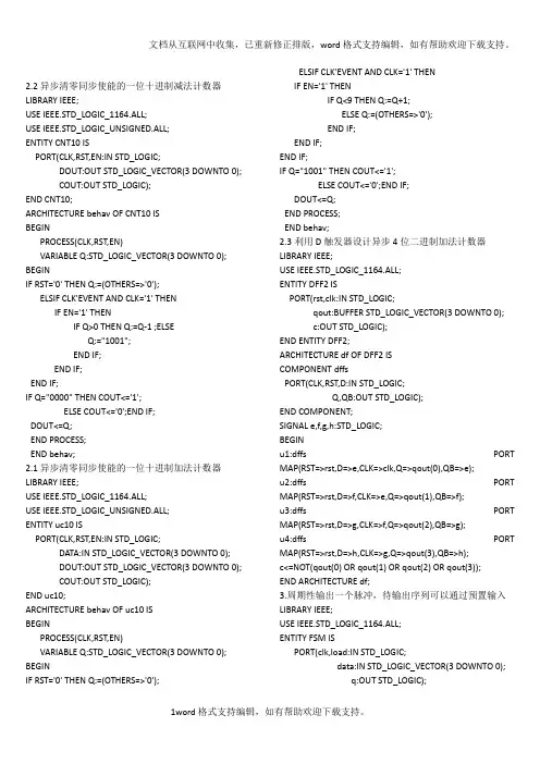
2.2异步清零同步使能的一位十进制减法计数器LIBRARY IEEE;USE IEEE.STD_LOGIC_1164.ALL;USE IEEE.STD_LOGIC_UNSIGNED.ALL;ENTITY CNT10 ISPORT(CLK,RST,EN:IN STD_LOGIC;DOUT:OUT STD_LOGIC_VECTOR(3 DOWNTO 0);COUT:OUT STD_LOGIC);END CNT10;ARCHITECTURE behav OF CNT10 ISBEGINPROCESS(CLK,RST,EN)VARIABLE Q:STD_LOGIC_VECTOR(3 DOWNTO 0); BEGINIF RST='0' THEN Q:=(OTHERS=>'0');ELSIF CLK'EVENT AND CLK='1' THENIF EN='1' THENIF Q>0 THEN Q:=Q-1 ;ELSEQ:="1001";END IF;END IF;END IF;IF Q="0000" THEN COUT<='1';ELSE COUT<='0';END IF;DOUT<=Q;END PROCESS;END behav;2.1异步清零同步使能的一位十进制加法计数器LIBRARY IEEE;USE IEEE.STD_LOGIC_1164.ALL;USE IEEE.STD_LOGIC_UNSIGNED.ALL;ENTITY uc10 ISPORT(CLK,RST,EN:IN STD_LOGIC;DATA:IN STD_LOGIC_VECTOR(3 DOWNTO 0);DOUT:OUT STD_LOGIC_VECTOR(3 DOWNTO 0);COUT:OUT STD_LOGIC);END uc10;ARCHITECTURE behav OF uc10 ISBEGINPROCESS(CLK,RST,EN)VARIABLE Q:STD_LOGIC_VECTOR(3 DOWNTO 0); BEGINIF RST='0' THEN Q:=(OTHERS=>'0');ELSIF CLK'EVENT AND CLK='1' THENIF EN='1' THENIF Q<9 THEN Q:=Q+1;ELSE Q:=(OTHERS=>'0');END IF;END IF;END IF;IF Q="1001" THEN COUT<='1';ELSE COUT<='0';END IF;DOUT<=Q;END PROCESS;END behav;2.3利用D触发器设计异步4位二进制加法计数器LIBRARY IEEE;USE IEEE.STD_LOGIC_1164.ALL;ENTITY DFF2 ISPORT(rst,clk:IN STD_LOGIC;qout:BUFFER STD_LOGIC_VECTOR(3 DOWNTO 0);c:OUT STD_LOGIC);END ENTITY DFF2;ARCHITECTURE df OF DFF2 ISCOMPONENT dffsPORT(CLK,RST,D:IN STD_LOGIC;Q,QB:OUT STD_LOGIC);END COMPONENT;SIGNAL e,f,g,h:STD_LOGIC;BEGINu1:dffs PORT MAP(RST=>rst,D=>e,CLK=>clk,Q=>qout(0),QB=>e);u2:dffs PORT MAP(RST=>rst,D=>f,CLK=>e,Q=>qout(1),QB=>f);u3:dffs PORT MAP(RST=>rst,D=>g,CLK=>f,Q=>qout(2),QB=>g);u4:dffs PORT MAP(RST=>rst,D=>h,CLK=>g,Q=>qout(3),QB=>h);c<=NOT(qout(0) OR qout(1) OR qout(2) OR qout(3));END ARCHITECTURE df;3.周期性输出一个脉冲,待输出序列可以通过预置输入LIBRARY IEEE;USE IEEE.STD_LOGIC_1164.ALL;ENTITY FSM ISPORT(clk,load:IN STD_LOGIC;data:IN STD_LOGIC_VECTOR(3 DOWNTO 0);q:OUT STD_LOGIC);END FSM;ARCHITECTURE bhv OF FSM ISTYPE STATES IS(s0,s1,s2,s3);SIGNAL c_st,next_state:STATES;SIGNAL a:STD_LOGIC_VECTOR(3 DOWNTO 0);BEGINREG:PROCESS(load,clk) BEGINIF load='1' THEN a<=data; end IF;IF CLK='1' AND CLK'EVENT THEN c_st<=next_state;END IF; END PROCESS REG;COM:PROCESS(c_st) BEGINCASE c_st ISWHEN s0=>q<=a(3);next_state<=s1;WHEN s1=>q<=a(2);next_state<=s2;WHEN s2=>q<=a(1);next_state<=s3;WHEN s3=>q<=a(0);next_state<=s0;WHEN OTHERS=>next_state<=s0;END CASE;END PROCESS COM;END bhv;4.巴克码识别LIBRARY IEEE;USE IEEE.STD_LOGIC_1164.ALL;ENTITY SCHK ISPORT(DIN,CLK,RST:IN STD_LOGIC;SOUT:OUT STD_LOGIC);END SCHK;ARCHITECTURE BHV OF SCHK ISTYPE STATES IS(s0,s1,s2,s3,s4,s5,s6,s7);SIGNAL ST,NST:STATES:=s0;BEGINCOM:PROCESS(ST,DIN) BEGINCASE ST IS--1110010WHEN s0=> IF DIN='1' THEN NST<=s1;ELSE NST<=s0;END IF;WHEN s1=> IF DIN='1' THEN NST<=s2;ELSE NST<=s0;END IF;WHEN s2=> IF DIN='1' THEN NST<=s3;ELSE NST<=s0;END IF;WHEN s3=> IF DIN='0' THEN NST<=s4;ELSE NST<=s3;END IF;WHEN s4=> IF DIN='0' THEN NST<=s5;ELSE NST<=s1;END IF;WHEN s5=> IF DIN='1' THEN NST<=s6;ELSE NST<=s0;END IF;WHEN s6=> IF DIN='0' THEN NST<=s7;ELSE NST<=s2;END IF;WHEN s7=> IF DIN='0' THEN NST<=s0;ELSE NST<=s1;END IF;WHEN OTHERS =>NST<=s0;END CASE;END PROCESS;REG: PROCESS (CLK,RST) BEGINIF RST='1' THEN ST<=s0;ELSIF CLK'EVENT AND CLK='1' THEN ST<=NST;END IF; END PROCESS REG;SOUT<='1' WHEN ST=s7 ELSE '0';END BHV;5.数控分频器LIBRARY IEEE;USE IEEE.STD_LOGIC_1164.ALL;USE IEEE.STD_LOGIC_UNSIGNED.ALL;ENTITY MHZ ISPORT(CLK:IN STD_LOGIC;OUTP:OUT STD_LOGIC);END MHZ;ARCHITECTURE BHV OF MHZ ISSIGNAL CLKT: STD_LOGIC;SIGNAL OUTM,OUTM_TMP:STD_LOGIC;SIGNAL COUNTM:INTEGER RANGE 47 DOWNTO 0; SIGNAL L:INTEGER RANGE 243 DOWNTO 0;SIGNAL TONE: INTEGER RANGE 243 DOWNTO 0; BEGINPROCESS(CLK)VARIABLE Q:STD_LOGIC_VECTOR(15 DOWNTO 0); BEGINIF CLK'EVENT AND CLK='1' THENIF Q=31999 THEN Q:=(OTHERS=>'0');CLKT<='1';ELSE Q:=Q+1;CLKT<='0';END IF;END IF;END PROCESS;PROCESS(CLKT)BEGINIF CLKT'EVENT AND CLKT='1' THENIF COUNTM=47 THEN COUNTM<=0;ELSE COUNTM<=COUNTM+1;END IF;END IF;END PROCESS;PROCESS(COUNTM)BEGINCASE COUNTM ISWHEN 0 => TONE<=163;WHEN 1 => TONE<=163;。
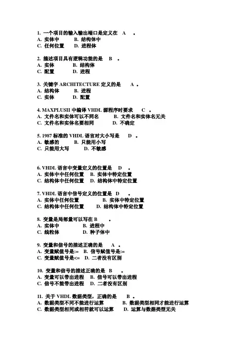
1. 一个项目的输入输出端口是定义在 A 。
A. 实体中B. 结构体中C. 任何位置D. 进程体2. 描述项目具有逻辑功能的是 B 。
A. 实体B. 结构体C. 配置D. 进程3. 关键字ARCHITECTURE定义的是 A 。
A. 结构体B. 进程C. 实体D. 配置4. MAXPLUSII中编译VHDL源程序时要求 C 。
A. 文件名和实体可以不同名B. 文件名和实体名无关C. 文件名和实体名要相同D. 不确定5. 1987标准的VHDL语言对大小写是 D 。
A. 敏感的B. 只能用小写C. 只能用大写D. 不敏感6. VHDL语言中变量定义的位置是 D 。
A. 实体中中任何位置B. 实体中特定位置C. 结构体中任何位置D. 结构体中特定位置7. VHDL语言中信号定义的位置是 D 。
A. 实体中任何位置B. 实体中特定位置C. 结构体中任何位置D. 结构体中特定位置8. 变量是局部量可以写在 B 。
A. 实体中B. 进程中C. 线粒体D. 种子体中9. 变量和信号的描述正确的是 A 。
A. 变量赋值号是:=B. 信号赋值号是:=C. 变量赋值号是<=D. 二者没有区别10. 变量和信号的描述正确的是 B 。
A. 变量可以带出进程B. 信号可以带出进程C. 信号不能带出进程D. 二者没有区别11. 关于VHDL数据类型,正确的是 B 。
A. 数据类型不同不能进行运算B. 数据类型相同才能进行运算C. 数据类型相同或相符就可以运算D. 运算与数据类型无关12. 下面数据中属于实数的是 B 。
A. 4.2B. 3C. …1‟D. “11011”13. 下面数据中属于位矢量的是 D 。
A. 4.2B. 3C. …1‟D. “11011”14. 关于VHDL数据类型,正确的是 B 。
A. 用户不能定义子类型B. 用户可以定义子类型C. 用户可以定义任何类型的数据D. 前面三个答案都是错误的15. 可以不必声明而直接引用的数据类型是 C 。

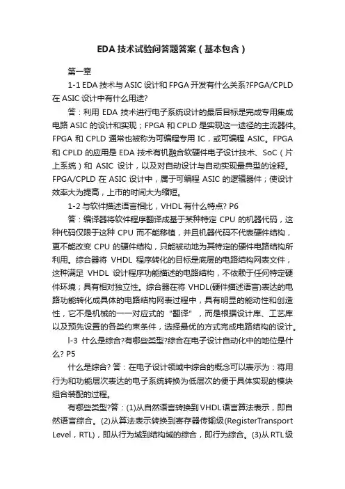
EDA技术试验问答题答案(基本包含)第一章1-1 EDA技术与ASIC设计和FPGA开发有什么关系?FPGA/CPLD 在ASIC设计中有什么用途?答:利用EDA技术进行电子系统设计的最后目标是完成专用集成电路ASIC的设计和实现;FPGA和CPLD是实现这一途径的主流器件。
FPGA和CPLD通常也被称为可编程专用IC,或可编程ASIC。
FPGA 和CPLD的应用是EDA技术有机融合软硬件电子设计技术、SoC(片上系统)和ASIC设计,以及对自动设计与自动实现最典型的诠释。
FPGA/CPLD在ASIC设计中,属于可编程ASIC的逻辑器件;使设计效率大为提高,上市的时间大为缩短。
1-2与软件描述语言相比,VHDL有什么特点? P6答:编译器将软件程序翻译成基于某种特定CPU的机器代码,这种代码仅限于这种CPU而不能移植,并且机器代码不代表硬件结构,更不能改变CPU的硬件结构,只能被动地为其特定的硬件电路结构所利用。
综合器将VHDL程序转化的目标是底层的电路结构网表文件,这种满足VHDL设计程序功能描述的电路结构,不依赖于任何特定硬件环境;具有相对独立性。
综合器在将VHDL(硬件描述语言)表达的电路功能转化成具体的电路结构网表过程中,具有明显的能动性和创造性,它不是机械的一一对应式的“翻译”,而是根据设计库、工艺库以及预先设置的各类约束条件,选择最优的方式完成电路结构的设计。
l-3什么是综合?有哪些类型?综合在电子设计自动化中的地位是什么? P5什么是综合? 答:在电子设计领域中综合的概念可以表示为:将用行为和功能层次表达的电子系统转换为低层次的便于具体实现的模块组合装配的过程。
有哪些类型?答:(1)从自然语言转换到VHDL语言算法表示,即自然语言综合。
(2)从算法表示转换到寄存器传输级(RegisterTransport Level,RTL),即从行为域到结构域的综合,即行为综合。
(3)从RTL级表示转换到逻辑门(包括触发器)的表示,即逻辑综合。
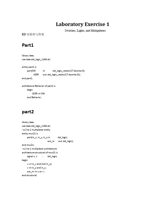
Laboratory Exercise 1Switches, Lights, and Multiplexers ED实验参与答案Part1library ieee;use ieee.std_logic_1164.all;entity part1 isport(SW:in std_logic_vector(17 downto 0);LEDR:out std_logic_vector(17 downto 0));end part1;architecture Behavior of part1 isbeginLEDR <= SW;end Behavior;part2library ieee;use ieee.std_logic_1164.all;--a 2 to 1 multiplexer entityentity mux21 isport(in_x, in_y, in_s:in std_logic;out_m:out std_logic);end mux21;--a 2 to 1 multiplexer architecturearchitecture structural of mux21 issignal u, v:std_logic;beginu <= in_x and (not in_s);v <= in_y and in_s ;out_m <= u or v ;end structural;--a eight-bit wide 2 to 1 multiplexerlibrary ieee;use ieee.std_logic_1164.all;--eight-bit wide 2 to 1 multiplexer entityentity mux21_8bit isport(SW: in std_logic_vector (17 downto 0);--SW: in std_logic_vector (15 downto 8);--SW: in std_logic_vector (17 downto 17);LEDR: out std_logic_vector (7 downto 0));end mux21_8bit;--eight-bit wide 2 to 1 multiplexera rchitecturearchitecture Structural of mux21_8bit iscomponent mux21port(in_x, in_y, in_s:in std_logic;out_m:out std_logic);end component;beginU1:mux21port map (in_x=>SW(0), in_y=>SW(8), in_s=>SW(17), out_m=>LEDR(0));U2:mux21port map (in_x=>SW(1), in_y=>SW(9), in_s=>SW(17), out_m=>LEDR(1));U3:mux21port map (in_x=>SW(2), in_y=>SW(10), in_s=>SW(17), out_m=>LEDR(2));U4:mux21port map (in_x=>SW(3), in_y=>SW(11), in_s=>SW(17), out_m=>LEDR(3));U5:mux21port map (in_x=>SW(4), in_y=>SW(12), in_s=>SW(17), out_m=>LEDR(4));U6:mux21port map (in_x=>SW(5), in_y=>SW(13), in_s=>SW(17), out_m=>LEDR(5));U7:mux21port map (in_x=>SW(6), in_y=>SW(14), in_s=>SW(17), out_m=>LEDR(6));U8:mux21port map (in_x=>SW(7), in_y=>SW(15), in_s=>SW(17), out_m=>LEDR(7));end Structural;part3library ieee;use ieee.std_logic_1164.all;--a 2 to 1 multiplexer entityentity mux21 isport(in_x, in_y, in_s:in std_logic;out_m:out std_logic);end mux21;--a 2 to 1 multiplexer architecturearchitecture structural of mux21 issignal signal_u, signal_v:std_logic;beginsignal_u <= in_x and (not in_s);signal_v <= in_y and in_s ;out_m <= signal_u or signal_v ;end structural;library ieee;use ieee.std_logic_1164.all;--a 5 to 1 multiplexer entityentity mux51 isport(in5_u, in5_v, in5_w, in5_x, in5_y, in5_s1, in5_s2, in5_s0:in std_logic;out5_m:out std_logic);end mux51;--a 5 to 1 multiplexer architecturearchitecture Structural of mux51 iscomponent mux21port (in_x, in_y, in_s:in std_logic;out_m:out std_logic);end component;signal signal_a, signal_b, signal_c:std_logic;beginU1:mux21port map (in_x=>in5_u, in_y=>in5_v, in_s=>in5_s0, out_m=>signal_a);U2:mux21port map (in_x=>in5_w, in_y=>in5_x, in_s=>in5_s0, out_m=>signal_b);U3:mux21port map (in_x=>signal_a, in_y=>signal_b, in_s=>in5_s1, out_m=>signal_c);U4:mux21port map (in_x=>signal_c, in_y=>in5_y, in_s=>in5_s2, out_m=>out5_m);end Structural;library ieee;use ieee.std_logic_1164.all;--a 3bit 5 to 1 multiplexer entityentity mux51_3bit isport(SW: in std_logic_vector (17 downto 0);LEDR: out std_logic_vector (17 downto 0);LEDG: out std_logic_vector (2 downto 0));end mux51_3bit;--a 3bit 5 to 1 multiplexer architecturearchitecture structural of mux51_3bit iscomponent mux51port(in5_u, in5_v, in5_w, in5_x, in5_y, in5_s1, in5_s2, in5_s0:in std_logic;out5_m:out std_logic);end component;beginLEDR <= sw;U1:mux51 port map (in5_u=>SW(0), in5_v=>SW(3), in5_w=>SW(6), in5_x=>SW(9), in5_y=>SW(12),in5_s0=>SW(15), in5_s1=>SW(16), in5_s2=>SW(17), out5_m=>LEDG(0));U2:mux51 port map (in5_u=>SW(1), in5_v=>SW(4), in5_w=>SW(7), in5_x=>SW(10), in5_y=>SW(13),in5_s0=>SW(15), in5_s1=>SW(16), in5_s2=>SW(17), out5_m=>LEDG(1));U3:mux51 port map (in5_u=>SW(2), in5_v=>SW(5), in5_w=>SW(8), in5_x=>SW(11), in5_y=>SW(14),in5_s0=>SW(15), in5_s1=>SW(16), in5_s2=>SW(17), out5_m=>LEDG(2));end structural;part4library ieee;use ieee.std_logic_1164.all;--a 7-segment decoder entityentity decoder isport(decoder_in_3:in std_logic_vector(2 downto 0);HEX0:out std_logic_vector(0 to 6));end decoder;-- a 7-segment decorder architecturearchitecture behavioral of decoder isbeginprocess(decoder_in_3)begincase decoder_in_3 iswhen "000"=> HEX0<= "0001001";when "001"=> HEX0 <= "0000110";when "010"=> HEX0 <= "1000110";when "011"=> HEX0 <= "1000000";when others => Hex0 <= "1111111";end case;end process;end behavioral;part5library ieee;use ieee.std_logic_1164.all;entity part5 isport(SW: in std_logic_vector(17 downto 0);HEX0,HEX1,HEX2,HEX3,HEX4: out std_logic_vector(6 downto 0));end part5;architecture Behavior of part5 iscomponent mux51_seg7port(Mux51_seg7_in: in std_logic_vector(17 downto 0);Seg: out std_logic_vector(6 downto 0));end component;beginU0:mux51_seg7port map(Mux51_seg7_in=>SW,Seg=>HEX0);U1:mux51_seg7port map(Mux51_seg7_in(17 downto 15)=>SW(17 downto 15), Mux51_seg7_in(14 downto 12)=>SW(11 downto 9),Mux51_seg7_in(11 downto 9)=>SW(8 downto 6), Mux51_seg7_in(8 downto 6)=>SW(5 downto 3),Mux51_seg7_in(5 downto 3)=>SW(2 downto 0), Mux51_seg7_in(2 downto 0)=>SW(14 downto 12),Seg=>HEX1);U2:mux51_seg7port map(Mux51_seg7_in(17 downto 15)=>SW(17 downto 15), Mux51_seg7_in(14 downto 12)=>SW(8 downto 6),Mux51_seg7_in(11 downto 9)=>SW(5 downto 3), Mux51_seg7_in(8 downto 6)=>SW(2 downto 0),Mux51_seg7_in(5 downto 3)=>SW(14 downto 12), Mux51_seg7_in(2 downto 0)=>SW(11 downto 9),Seg=>HEX2);U3:mux51_seg7port map(Mux51_seg7_in(17 downto 15)=>SW(17 downto 15), Mux51_seg7_in(14 downto 12)=>SW(5 downto 3),Mux51_seg7_in(11 downto 9)=>SW(2 downto 0), Mux51_seg7_in(8 downto 6)=>SW(14 downto 12),Mux51_seg7_in(5 downto 3)=>SW(11 downto 9), Mux51_seg7_in(2 downto 0)=>SW(8 downto 6),Seg=>HEX3);U4:mux51_seg7port map(Mux51_seg7_in(17 downto 15)=>SW(17 downto 15), Mux51_seg7_in(14 downto 12)=>SW(2 downto 0),Mux51_seg7_in(11 downto 9)=>SW(14 downto 12), Mux51_seg7_in(8 downto 6)=>SW(11 downto 9),Mux51_seg7_in(5 downto 3)=>SW(8 downto 6), Mux51_seg7_in(2 downto 0)=>SW(5 downto 3),Seg=>HEX4);end Behavior;----------------------------------------------------------------------------------------------------------A circuit that can select and display one of five characters-----------------------------------------------------------------------------------------------------------------------library ieee;use ieee.std_logic_1164.all;entity mux51_seg7 isport(Mux51_seg7_in: in std_logic_vector(17 downto 0);Seg: out std_logic_vector(6 downto 0));end mux51_seg7;architecture Behavior of mux51_seg7 iscomponent mux51_3bitport(S, U, V, W, X, Y: in std_logic_vector(2 downto 0);M: out std_logic_vector(2 downto 0));end component;component char_7segport(C: in std_logic_vector(2 downto 0);Display: out std_logic_vector(6 downto 0));end component;signal M : std_logic_vector(2 downto 0);beginM0: mux51_3bit port map(Mux51_seg7_in(17 downto 15), Mux51_seg7_in(14 downto 12),Mux51_seg7_in(11 downto 9),Mux51_seg7_in(8 downto 6),Mux51_seg7_in(5 downto 3),Mux51_seg7_in(2 downto 0),M);H0: char_7seg port map(M, Seg);end Behavior;-----------------------------------------------------------------------------------------------------------------------------a 3bit mux51----------------------------------------------------------------------------------------------------------------------------------------------------library ieee;use ieee.std_logic_1164.all;--a 2 to 1 multiplexer entityentity mux21 isport(in_x, in_y, in_s:in std_logic;out_m:out std_logic);end mux21;--a 2 to 1 multiplexer architecturearchitecture structural of mux21 issignal signal_u, signal_v:std_logic;beginsignal_u <= in_x and (not in_s);signal_v <= in_y and in_s ;out_m <= signal_u or signal_v ;end structural;library ieee;use ieee.std_logic_1164.all;--a 5 to 1 multiplexer entityentity mux51 isport(in5_u, in5_v, in5_w, in5_x, in5_y, in5_s1, in5_s2, in5_s0:in std_logic;out5_m:out std_logic);end mux51;--a 5 to 1 multiplexer architecturearchitecture Structural of mux51 iscomponent mux21port (in_x, in_y, in_s:in std_logic;out_m:out std_logic);end component;signal signal_a, signal_b, signal_c:std_logic;beginU1:mux21port map (in_x=>in5_u, in_y=>in5_v, in_s=>in5_s0, out_m=>signal_a);U2:mux21port map (in_x=>in5_w, in_y=>in5_x, in_s=>in5_s0, out_m=>signal_b);U3:mux21port map (in_x=>signal_a, in_y=>signal_b, in_s=>in5_s1, out_m=>signal_c);U4:mux21port map (in_x=>signal_c, in_y=>in5_y, in_s=>in5_s2, out_m=>out5_m);end Structural;-----------------------------------------------------------------------------------------------------------------------------a 3bit 5 to 1 multiplexer---------------------------------------------------------------------------------------------------------------------------------------library ieee;use ieee.std_logic_1164.all;--a 3bit 5 to 1 multiplexer entityentity mux51_3bit isport(S, U, V, W, X, Y: in std_logic_vector (2 downto 0);M: out std_logic_vector (2 downto 0));end mux51_3bit;--a 3bit 5 to 1 multiplexer architecturearchitecture structural of mux51_3bit iscomponent mux51port(in5_u, in5_v, in5_w, in5_x, in5_y, in5_s1, in5_s2, in5_s0:in std_logic;out5_m:out std_logic);end component;beginU1:mux51 port map (in5_u=>U(0), in5_v=>V(0), in5_w=>W(0), in5_x=>X(0), in5_y=>Y(0),in5_s0=>S(0), in5_s1=>S(1), in5_s2=>S(2), out5_m=>M(0));U2:mux51 port map (in5_u=>U(1), in5_v=>V(1), in5_w=>W(1), in5_x=>X(1), in5_y=>Y(1),in5_s0=>S(0), in5_s1=>S(1), in5_s2=>S(2), out5_m=>M(1));U3:mux51 port map (in5_u=>U(2), in5_v=>V(2), in5_w=>W(2), in5_x=>X(2), in5_y=>Y(2),in5_s0=>S(0), in5_s1=>S(1), in5_s2=>S(2), out5_m=>M(2));end structural;-----------------------------------------------------------------------------------------------------------------------------a 7-segment decoder---------------------------------------------------------------------------------------------------------------------------------------------library ieee;use ieee.std_logic_1164.all;--a 7-segment decoder entityentity char_7seg isport(C:in std_logic_vector(2 downto 0);Display:out std_logic_vector(6 downto 0));end char_7seg;-- a 7-segment decorder architecturearchitecture behavioral of char_7seg isbeginprocess(C)begincase C iswhen "000"=> Display <= "0001001";when "001"=> Display <= "0000110";when "010"=> Display <= "1000111";when "011"=> Display <= "1000000";when others => Display <= "1111111";end case;end process;end behavioral;part6--------------------------------------------------------------------------------------------------------------Rotating the word HELLO on eight displays.----------------------------------SW(17~15): select--SW(14~12): H--SW(11~9):E--SW(8~6):L--SW(5~3):O--SW(2~0):none---------------------------------------------------------------------------------------------library ieee;use ieee.std_logic_1164.all;entity part6 isport(SW: in std_logic_vector(17 downto 0);HEX0,HEX1,HEX2,HEX3,HEX4,HEX5,HEX6,HEX7: out std_logic_vector(6 downto 0)); end part6;architecture Behavior of part6 iscomponent mux81_seg7port(S, D0, D1, D2, D3, D4, D5, D6, D7: in std_logic_vector(2 downto 0);Seg: out std_logic_vector(6 downto 0));end component;beginU0:mux81_seg7port map(S=>SW(17 downto 15),D0=>SW(2 downto 0),D1=>SW(2 downto 0),D2=>SW(2 downto 0),D3=>SW(14 downto 12),D4=>SW(11 downto 9),D5=>SW(8 downto 6),D6=>SW(8 downto 6),D7=>SW(5 downto 3),Seg=>HEX0);U1:mux81_seg7port map(S=>SW(17 downto 15),D0=>SW(2 downto 0),D1=>SW(2 downto 0),D2=>SW(14 downto 12),D3=>SW(11 downto 9),D4=>SW(8 downto 6),D5=>SW(8 downto 6),D6=>SW(5 downto 3),D7=>SW(2 downto 0),Seg=>HEX1);U2:mux81_seg7port map(S=>SW(17 downto 15),D0=>SW(2 downto 0),D1=>SW(14 downto 12),D2=>SW(11 downto 9),D3=>SW(8 downto 6),D4=>SW(8 downto 6),D5=>SW(5 downto 3),D6=>SW(2 downto 0),D7=>SW(2 downto 0),Seg=>HEX2);U3:mux81_seg7port map(S=>SW(17 downto 15),D0=>SW(14 downto 12),D1=>SW(11downto 9),D2=>SW(8 downto 6),D3=>SW(8 downto 6),D4=>SW(5 downto 3),D5=>SW(2 downto 0),D6=>SW(2 downto 0),D7=>SW(2 downto 0),Seg=>HEX3);U4:mux81_seg7port map(S=>SW(17 downto 15),D0=>SW(11 downto 9),D1=>SW(8 downto 6),D2=>SW(8 downto 6),D3=>SW(5 downto 3),D4=>SW(2 downto 0),D5=>SW(2 downto 0),D6=>SW(2 downto 0),D7=>SW(14 downto 12),Seg=>HEX4);U5:mux81_seg7port map(S=>SW(17 downto 15),D0=>SW(8 downto 6),D1=>SW(8 downto 6),D2=>SW(5 downto 3),D3=>SW(2 downto 0),D4=>SW(2 downto 0),D5=>SW(2 downto 0),D6=>SW(14 downto 12),D7=>SW(11 downto 9),Seg=>HEX5);U6:mux81_seg7port map(S=>SW(17 downto 15),D0=>SW(8 downto 6),D1=>SW(5 downto 3),D2=>SW(2 downto 0),D3=>SW(2 downto 0),D4=>SW(2 downto 0),D5=>SW(14 downto 12),D6=>SW(11 downto 9),D7=>SW(8 downto 6),Seg=>HEX6);U7:mux81_seg7port map(S=>SW(17 downto 15),D0=>SW(5 downto 3),D1=>SW(2 downto 0),D2=>SW(2 downto 0),D3=>SW(2 downto 0),D4=>SW(14 downto 12),D5=>SW(11 downto 9),D6=>SW(8 downto 6),D7=>SW(8 downto 6),Seg=>HEX7);end Behavior;----------------------------------------------------------------------------------------------------------A circuit that can select and display one of eight characters----------------------------------------------------------------------------------------------------------------------library ieee;use ieee.std_logic_1164.all;--eht mux81_seg7 entityentity mux81_seg7 isport(S, D0, D1, D2, D3, D4, D5, D6, D7: in std_logic_vector(2 downto 0);Seg: out std_logic_vector(6 downto 0));end mux81_seg7;--the mux81_seg7 architecturearchitecture Behavior of mux81_seg7 iscomponent mux81_3bitport(S, D0, D1, D2, D3, D4, D5, D6, D7: in std_logic_vector(2 downto 0);M: out std_logic_vector(2 downto 0));end component;component char_7segport(C: in std_logic_vector(2 downto 0);Display: out std_logic_vector(6 downto 0));end component;signal M1 : std_logic_vector(2 downto 0);beginM0: mux81_3bit port map(S, D0, D1, D2, D3, D4, D5, D6, D7,M1);H0: char_7seg port map(M1, Seg);end Behavior;-----------------------------------------------------------------------------------------------------------------------------a 3bit mux81----------------------------------------------------------------------------------------------------------------------------------------------------library ieee;use ieee.std_logic_1164.all;--a 3bit multiplexer 8 to 1 entityentity mux81_3bit isport(S, D0, D1, D2, D3, D4, D5, D6, D7: in std_logic_vector(2 downto 0);M: out std_logic_vector(2 downto 0)); end mux81_3bit;--a 3bit multiplexer 8 to 1 architecturearchitecture behavioral of mux81_3bit isbeginwith S selectM <= D0when "000",D1 when "001",D2 when "010",D3 when "011",D4 when "100",D5 when "101",D6 when "110",D7 when "111","ZZZ"when others;end behavioral;-----------------------------------------------------------------------------------------------------------------------------a 7-segment decoder---------------------------------------------------------------------------------------------------------------------------------------------library ieee;use ieee.std_logic_1164.all;--a 7-segment decoder entityentity char_7seg isport(C:in std_logic_vector(2 downto 0);Display:out std_logic_vector(6 downto 0));end char_7seg;-- a 7-segment decorder architecturearchitecture behavioral of char_7seg isbeginprocess(C)begincase C iswhen "000"=> Display <= "0001001";when "001"=> Display <= "0000110";when "010"=> Display <= "1000111";when "011"=> Display <= "1000000";when others => Display <= "1111111";end case;end process;end behavioral;。
eda习题与答案
EDA习题与答案
探索性数据分析(EDA)是数据科学中的一项重要技能,通过对数据进行可视化和统计分析,可以帮助我们更好地理解数据的特征和规律。
在实际应用中,我们经常会遇到各种EDA习题,下面就让我们一起来看看一些常见的EDA习题及其答案。
1. 习题:对一组学生的考试成绩进行EDA,包括成绩的分布、平均分、及格率等统计指标。
答案:首先,我们可以绘制成绩的直方图,以了解成绩的分布情况。
然后计算平均分和及格率,可以通过描述性统计方法来实现。
最后,我们还可以使用箱线图来展示成绩的离散程度和异常值情况。
2. 习题:分析一组房屋价格数据,探索价格的变化趋势和影响因素。
答案:首先,我们可以绘制价格随时间变化的折线图,以了解价格的趋势。
然后可以使用相关系数分析价格与其他因素(如面积、地段、装修等)的关系。
最后,可以利用散点图和回归分析来探讨价格与各种因素之间的关联性。
3. 习题:分析一组销售数据,探索销售额的季节性变化和产品销售额的贡献比例。
答案:首先,可以使用折线图或柱状图来展示销售额随时间的变化情况,以了解销售额的季节性变化。
然后,可以计算各个产品在总销售额中的贡献比例,以了解产品销售情况的分布。
通过以上习题及其答案的分析,我们可以看到EDA在实际应用中的重要性和灵活性。
通过对数据进行可视化和统计分析,我们可以更好地理解数据的特征和
规律,为后续的数据建模和决策提供有力支持。
因此,掌握好EDA技能对于数据科学从业者来说至关重要。
EDA课后题答案第⼀章1.什么叫EDA技术?及狭义定义(书P1)Electronic Design Automation--电⼦设计⾃动化。
EDA的⼴义定义范围包括:半导体⼯艺设计⾃动化、可编程器件设计⾃动化、电⼦系统设计⾃动化、印刷电路板设计⾃动化、仿真与测试、故障诊断⾃动化、形式验证⾃动化统称EDA⼯程。
2.EDA发展历程:CAD- CAE -EDA3 .EDA技术的主要内容实现载体(硬件基础):⼤规模可编程逻辑器件(PLD_Programmable Logic Device)描述⽅式:硬件描述语⾔(HDL_Hard descripation Lauguage,VHDL,Verilog HDL等)设计⼯具:开发软件、开发系统硬件验证:实验开发系统FPGA 在结构上主要分为三个部分,即可编程逻辑单元,可编程输⼊/输出单元和可编程连线三个部分。
CPLD在结构上主要包括三个部分,即可编程逻辑宏单元,可编程输⼊/输出单元和可编程内部连线。
4.硬件描述语⾔(HDL_Hardware Description Language)VHDL:IEEE标准硬件描述语⾔,在电⼦⼯程领域,已成为事实上的通⽤硬件描述语⾔。
系统级抽象描述能⼒较强。
Verilog:⽀持的EDA⼯具较多,适⽤于RTL级和门电路级的描述,其综合过程较VHDL 稍简单,门级开关电路描述能级较强,但其在⾼级描述⽅⾯不如VHDL。
ABEL:⼀种⽀持各种不同输⼊⽅式的HDL,系统级抽象描述能⼒差,适应于门级电路描述。
5. 仿真⼯具功能仿真(也叫前仿真、系统级仿真、⾏为仿真)验证系统的功能。
时序仿真(也叫后仿真、电路级仿真):验证系统的时序特性、系统性能。
6. EDA的⼯程设计流程(P8)第⼆章1.在系统可编程技术(ISP)定义ISP(In_System Programmability/Programming)是指对器件、电路板、整个电⼦系统进⾏逻辑重构和修改功能的能⼒。
第一章1- 1 EDA技术与ASIC设计与FPGA开发有什么关系?答:利用EDA技术进行电子系统设计得最后目标就是完成专用集成电路ASIC得设计与实现;FPGA与CPLD就是实现这一途径得主流器件。
FPGA与CPLD通常也被称为可编程专用IC,或可编程ASIC o FPGA与CPLD得应用就是EDA技术有机融合软硬件电子设计技术、SoC(片上系统)与ASIC设计,以及对自动设计与自动实现最典型得诠释。
1- 2与软件描述语言相比,VHDL有什么特点? P6答:编译器将软件程序翻译成基于某种特定CPU得机器代码,这种代码仅限于这种CPU而不能移植,并且机器代码不代表硬件结构,更不能改变CPU得硬件结构,只能被动地为其特定得硬件电路结构所利用。
综合器将VHDL程序转化得目标就是底层得电路结构网表文件,这种满足VHDL设计程序功能描述得电路结构,不依赖于任何特定硬件环境;具有相对独立性。
综合器在将VHDL(硬件描述语言)表达得电路功能转化成具体得电路结构网表过程中,具有明显得能动性与创造性,它不就是机械得一一对应式得“翻译”,而就是根据设计库、工艺库以及预先设置得各类约束条件,选择最优得方式完成电路结构得设计。
1- 3什么就是综合?有哪些类型?综合在电子设计自动化中得地位就是什么?什么就是综合?答:在电子设计领域中综合得概念可以表示为:将用行为与功能层次表达得电子系统转换为低层次得便于具体实现得模块组合装配得过程。
有哪些类型?答:(1)从自然语言转换到VHDL语言算法表示,即自然语言综合。
(2)从算法表示转换到寄存器传输级(RegisterTransport Level,RTL),即从行为域到结构域得综合,即行为综合。
(3)从RTL级表示转换到逻辑门(包括触发器)得表示,即逻辑综合。
(4)从逻辑门表示转换到版图表示(ASIC设计),或转换到FPGA得配置网表文件,可称为版图综合或结构综合。
综合在电子设计自动化中得地位就是什么?答:就是核心地位(见图1- 3)。
EDA精品课程试卷答案1《EDA技术》模拟试卷⼀参考答案:⼀、填空题(17空,每空2分,共34分)1、ASIC直译为___专⽤集成电路__________________________________2、EDA即_____电⼦设计⾃动化______________________________________。
3、CPLD和FPGA统称为_____⾼密度可编程逻辑器件______________4、MAX7000系列是Altera公司⽬前销量最⼤的产品,属于⾼性能/⾼密度的_CPLD___5、FLEX10K系列是Altera公司推出的主流产品,属于⾼密度,⾼速度的_FPGA____6、可编程逻辑器件的设计过程可以分为四个步骤_设计输⼊__,_设计实现____,_设计校验__,_下载编程_________7、⽬前应⽤最⼴泛的HDL(硬件描述语⾔)有___VHDL__,__Verilog-HDL_______8、MAX+plus提供了_CPLD/FPGA__的设计,仿真和烧写的环境,是⽬前使⽤极为⼴泛的EDA开发⼯具之⼀.9、构成⼀个完整的VHDL语⾔程序的五个基本结构是_实体__,_结构体__,_库____,_程序包__,__配置_。
⼆、选择题(21空,每空2分,共42分)1、LIBRARY ___A____;USE IEEE.STD_LOGIC_1164.ALL;A. IEEEB. STDC.WORK2、ENTITY counter ISPORT( Clk : IN STD_LOGIC;Q : BUFFER STD_LOGIC_VECTOR(2 DOWNTO 0));END ___B___________;A. counter23B. counterC. work3、ENTITY counter ISPORT( Clk : IN STD_LOGIC;Q : BUFFER STD_LOGIC_VECTOR(2 DOWNTO 0));…………….ARCHITECTURE a OF __B______ IS4、ARCHITECTURE a OF mux4 ISBEGIN…………………END ___A___;A.. aB. bC. c5、LIBRARY IEEE;USE IEEE.______A_____.ALL;A. STD_LOGIC_1164B. IEEE_LOGIC_1164C. WORK_LOGIC_11646、下列是⼀个四选⼀的数据选择器的实体,S,A,B,C,D是输⼊端,Y是输出端ENTITY multi_4v IS PORT(S :__A____ STD_LOGIC_VECTOR (1 DOWNTO 0);A,B,C,D :___A___ STD_LOGIC;Y :__B_____ STD_LOGIC);END multi_4v;A. IN B . OUT C. BUFFER7、下⾯是⼀个计数器的实体,clk是输⼊端,q是输出端ENTITY countclr ISPORT(clk :__A_____ STD_LOGIC;q :____C_____ STD_LOGIC_VECTOR(7 DOWNTO 0)); END countclr;ARCHITECTURE one OF countclr ISBEGIN………………A. INB. OUTC. BUFFER8、ARCHITECTURE one OF multi_4v IS_B_______……..END one;9、PROCESS(clk)V ARIABLE qtmp: STD_LOGIC_VECTOR(7 DOWNTO 0); ___C______IF clk'event AND clk='1' THEN……………….END PROCESS;A. INB. ENDC. BEGIN10、CASE D ISWHEN 0__A____ S___C____"0000001"; --0A. =>B. >=C. <=11、IF clr='0' THEN qtmp:="00000000";ELSE qtmp:=qtmp+1;____B____;A. END PROCESSB. END IFC. BEGIN12、IF j='0' AND k='0' THEN NULL;__C_____ j='0' AND k='1' THENqtmp<='0';A. ELSEIFB. ELSE IFC. ELSIF13、PROCESS(clk)V ARIABLE qtmp: STD_LOGIC_VECTOR(7 DOWNTO 0); BEGINIF clk'event AND clk='1' THENIF clr='0' THEN qtmp__C___"00000000";A. =>14、PROCESS(clk)___B______ qtmp: STD_LOGIC_VECTOR(7 DOWNTO 0);BEGINIF clk'event AND clk='1' THENIF clr='0' THEN qtmp<="00000000";A. V ARIABLEB.SIGNALC. BEGIN15、下⾯是循环移位寄存器的部分程序dout(4 DOWNTO 1)<=dout(3 DOWNTO 0);__C_____<=dout(4);A. dout(1)B. dout(3)C. dout(0)16、进程(process)语句是___B_____A. 顺序语句B. 并⾏语句C. 其它17、IF语句是__A__A. 顺序语句B. 并⾏语句C. 其它三、画出下列程序的原理图,并说明其功能。
EDA实验习题,本文属个人所写,仅供参考:--实验一(四选一):library ieee;use ieee.std_logic_1164.all;use ieee.std_logic_unsigned.all;entity mux41a isport(a,b,c,d,s0,s1:in std_logic;y:out std_logic);end entity mux41a;architecture four_ch_one of mux41a issignal ss_ctrl: std_logic_vector(1 downto 0);beginss_ctrl<=s1 & s0;process(a,b,c,d,ss_ctrl)begincase ss_ctrl iswhen "00"=> y<=a;when "01"=> y<=b;when "10"=> y<=c;when "11"=> y<=d;when others=>NULL;end case;end process;end architecture four_ch_one;--实验二(边沿、电平触发):Library ieee;use ieee.std_logic_1164.all; entity dff0 isport( CLK:in std_logic;D:in std_logic;Q1,Q2:out std_logic);end dff0;architecture bhv of dff0 issignal QQ:std_logic;beginPRO1:process(CLK) --upbeginif CLK'event and CLK='1'then QQ<=D;end if;end process;Q1<=QQ;PRO2:process(CLK,D) --high p beginif CLK='1'then Q2<=D;end if;end process;end bhv;--实验三(二位十进制数递减):library ieee;use ieee.std_logic_1164.all;use ieee.std_logic_unsigned.all;entity CNT10M isport(CLK,RST,EN:in std_logic;CQ:out std_logic_vector(3 downto 0); --个位递减输出BOUT:out std_logic_vector(3 downto 0)); --十位递减输出end CNT10M;architecture behav of CNT10M isbeginprocess(CLK,RST,EN)variable ge,shi:std_logic_vector(3 downto 0);beginif RST='1' then ge:=(others=>'0'); shi:=(others=>'0');elsif CLK'event and CLK='1' thenif EN='1' thenif ge>0 then ge:=ge-1;else ge:="1001";end if;if ge=9 then shi:=shi-1;else shi:=shi;end if;if shi<10 and shi>=0 then shi:=shi;else shi:="1001";end if;end if;end if;CQ<=ge;BOUT<=shi;end process;end behav;--实验四(5/9占空比分频器):library ieee;use ieee.std_logic_1164.all;use ieee.std_logic_unsigned.all;entity DIV_9 isport(CLK,RST,EN:in std_logic;DIV9:out std_logic);end DIV_9;architecture one of DIV_9 issignal FULL:std_logic;beginprocess(CLK)variable CNT9:std_logic_vector(3 downto 0);beginif RST='0' then CNT9:=(others=>'0');elsif CLK'event and CLK='1' thenif EN='1' thenif CNT9<8 then CNT9:=CNT9+1;else CNT9:=(others=>'0');end if;if CNT9>3 then FULL<='1';else FULL<='0';end if;end if;end if;DIV9<=FULL;end process;end one;--实验五(层次法8位全减器)--1,一位半减器AND2instNOT inst2XORinst7VCCmin_edINPUT VCCminINPUT oputOUTPUT h_braOUTPUT--2,一位全减器min_ed minh_bra oputh_minusinstmin_ed minh_bra oputh_minus inst1OR2inst6VCC min_ed INPUT VCCminINPUT VCCl_braINPUT h_braOUTPUT oputOUTPUT--3,8位全减器VCClow_braINPUT VCC min[0]INPUT VCC min_d[0]INPUT VCCmin[1]INPUT VCC min_d[1]INPUT VCCmin[2]INPUT VCC min_d[2]INPUT VCCmin[3]INPUT VCC min_d[3]INPUT VCCmin[4]INPUT VCC min_d[4]INPUT VCCmin[5]INPUT VCC min_d[5]INPUT VCCmin[6]INPUT VCC min_d[6]INPUT VCCmin[7]INPUT VCC min_d[7]INPUT oput[7]OUTPUToput[6]OUTPUT oput[5]OUTPUT oput[4]OUTPUT oput[3]OUTPUT oput[2]OUTPUT oput[1]OUTPUT oput[0]OUTPUT hign_bra OUTPUT m in_ed m in l_brah_bra oputf_m inusinstm in_ed m in l_brah_bra oputf_m inusinst1m in_ed m in l_brah_bra oputf_m inusinst2m in_ed m in l_brah_bra oputf_m inusinst3m in_ed m in l_brah_bra oputf_m inusinst4m in_ed m in l_brah_bra oputf_m inusinst5m in_ed m in l_brah_bra oputf_m inusinst6m in_ed m in l_brah_bra oputf_m inusinst7--实验六--1,内容一结果--2,内容二结果①③④实验习题:When others=>NULL 在case语句中的含义是:当case后面的变量或信号出现的当前情况,在以上when语句后面没有列举出来,这时被赋值的变量或者语句赋为NULL,即不作任何操作。
EDA电子课程实验报告专业:班级:姓名:学号:实验一四人表决器一实验目的1、熟悉Quartus II软件的使用。
2、熟悉EDA-IV实验箱。
3、熟悉EDA开发的基本流程。
二硬件需求1、RC-EDA-IV型实验箱一台;2、RC-EDA-IV型实验箱配套USB-Blaster下载器一个;3、PC机一台。
三实验原理所谓表决器就是对于一个行为,由多个人投票,如果同意的票数过半,就认为此行为可行;否则如果否决的票数过半,则认为此行为无效。
四人表决器顾名思义就是由四个人来投票,当同意的票数大于或者等于3人时,则认为同意;反之,当否决的票数大于或者等于2人时,则认为不同意。
实验中用4个拨挡开关来表示4个人,当对应的拨挡开关输入为‘1’时,表示此人同意;否则若拨挡开关输入为‘0’时,则表示此人反对。
表决的结果用一个LED表示,若表决的结果为同意,则LED被点亮;否则,如果表决的结果为反对,则LED不会被点亮。
四实验内容VHDL程序:library ieee;use ieee.std_logic_1164.all;use ieee.std_logic_arith.all;use ieee.std_logic_unsigned.all;--------------------------------------------------------------------entity EXP3 isport(k1,K2,K3,K4 : in std_logic;ledag : out std_logic_vector(3downto 0);m_Result : out std_logic);end EXP3;--------------------------------------------------------------------architecture behave of EXP3 issignal K_Num : std_logic_vector(2 downto 0); signal K1_Num,K2_Num: std_logic_vector(2 downto 0); signal K3_Num,K4_Num: std_logic_vector(2 downto 0);beginprocess(K1,K2,K3,K4)beginK1_Num<='0'&'0'&K1;K2_Num<='0'&'0'&K2;K3_Num<='0'&'0'&K3;K4_Num<='0'&'0'&K4;end process;process(K1_Num,K2_Num,K3_Num,K4_Num,)beginK_Num<=K1_Num+K2_Num+K3_Num+K4_Num;end process;process(K_Num) beginif(K_Num>2) thenm_Result<='1';elsem_Result<='0';end if;end process;end behave;实验电路实验二格雷码转换一实验目的1、了解格雷码变换的原理。
Laboratory Exercise 1Switches, Lights, and Multiplexers ED实验参与答案Part1library ieee;use ieee.std_logic_1164.all;entity part1 isport(SW:in std_logic_vector(17 downto 0);LEDR:out std_logic_vector(17 downto 0));end part1;architecture Behavior of part1 isbeginLEDR <= SW;end Behavior;part2library ieee;use ieee.std_logic_1164.all;--a 2 to 1 multiplexer entityentity mux21 isport(in_x, in_y, in_s:in std_logic;out_m:out std_logic);end mux21;--a 2 to 1 multiplexer architecturearchitecture structural of mux21 issignal u, v:std_logic;beginu <= in_x and (not in_s);v <= in_y and in_s ;out_m <= u or v ;end structural;--a eight-bit wide 2 to 1 multiplexerlibrary ieee;use ieee.std_logic_1164.all;--eight-bit wide 2 to 1 multiplexer entityentity mux21_8bit isport(SW: in std_logic_vector (17 downto 0);--SW: in std_logic_vector (15 downto 8);--SW: in std_logic_vector (17 downto 17);LEDR: out std_logic_vector (7 downto 0));end mux21_8bit;--eight-bit wide 2 to 1 multiplexera rchitecturearchitecture Structural of mux21_8bit iscomponent mux21port(in_x, in_y, in_s:in std_logic;out_m:out std_logic);end component;beginU1:mux21port map (in_x=>SW(0), in_y=>SW(8), in_s=>SW(17), out_m=>LEDR(0));U2:mux21port map (in_x=>SW(1), in_y=>SW(9), in_s=>SW(17), out_m=>LEDR(1));U3:mux21port map (in_x=>SW(2), in_y=>SW(10), in_s=>SW(17), out_m=>LEDR(2));U4:mux21port map (in_x=>SW(3), in_y=>SW(11), in_s=>SW(17), out_m=>LEDR(3));U5:mux21port map (in_x=>SW(4), in_y=>SW(12), in_s=>SW(17), out_m=>LEDR(4));U6:mux21port map (in_x=>SW(5), in_y=>SW(13), in_s=>SW(17), out_m=>LEDR(5));U7:mux21port map (in_x=>SW(6), in_y=>SW(14), in_s=>SW(17), out_m=>LEDR(6));U8:mux21port map (in_x=>SW(7), in_y=>SW(15), in_s=>SW(17), out_m=>LEDR(7));end Structural;part3library ieee;use ieee.std_logic_1164.all;--a 2 to 1 multiplexer entityentity mux21 isport(in_x, in_y, in_s:in std_logic;out_m:out std_logic);end mux21;--a 2 to 1 multiplexer architecturearchitecture structural of mux21 issignal signal_u, signal_v:std_logic;beginsignal_u <= in_x and (not in_s);signal_v <= in_y and in_s ;out_m <= signal_u or signal_v ;end structural;library ieee;use ieee.std_logic_1164.all;--a 5 to 1 multiplexer entityentity mux51 isport(in5_u, in5_v, in5_w, in5_x, in5_y, in5_s1, in5_s2, in5_s0:in std_logic;out5_m:out std_logic);end mux51;--a 5 to 1 multiplexer architecturearchitecture Structural of mux51 iscomponent mux21port (in_x, in_y, in_s:in std_logic;out_m:out std_logic);end component;signal signal_a, signal_b, signal_c:std_logic;beginU1:mux21port map (in_x=>in5_u, in_y=>in5_v, in_s=>in5_s0, out_m=>signal_a);U2:mux21port map (in_x=>in5_w, in_y=>in5_x, in_s=>in5_s0, out_m=>signal_b);U3:mux21port map (in_x=>signal_a, in_y=>signal_b, in_s=>in5_s1, out_m=>signal_c);U4:mux21port map (in_x=>signal_c, in_y=>in5_y, in_s=>in5_s2, out_m=>out5_m);end Structural;library ieee;use ieee.std_logic_1164.all;--a 3bit 5 to 1 multiplexer entityentity mux51_3bit isport(SW: in std_logic_vector (17 downto 0);LEDR: out std_logic_vector (17 downto 0);LEDG: out std_logic_vector (2 downto 0));end mux51_3bit;--a 3bit 5 to 1 multiplexer architecturearchitecture structural of mux51_3bit iscomponent mux51port(in5_u, in5_v, in5_w, in5_x, in5_y, in5_s1, in5_s2, in5_s0:in std_logic;out5_m:out std_logic);end component;beginLEDR <= sw;U1:mux51 port map (in5_u=>SW(0), in5_v=>SW(3), in5_w=>SW(6), in5_x=>SW(9), in5_y=>SW(12),in5_s0=>SW(15), in5_s1=>SW(16), in5_s2=>SW(17), out5_m=>LEDG(0));U2:mux51 port map (in5_u=>SW(1), in5_v=>SW(4), in5_w=>SW(7), in5_x=>SW(10), in5_y=>SW(13),in5_s0=>SW(15), in5_s1=>SW(16), in5_s2=>SW(17), out5_m=>LEDG(1));U3:mux51 port map (in5_u=>SW(2), in5_v=>SW(5), in5_w=>SW(8), in5_x=>SW(11), in5_y=>SW(14),in5_s0=>SW(15), in5_s1=>SW(16), in5_s2=>SW(17), out5_m=>LEDG(2));end structural;part4library ieee;use ieee.std_logic_1164.all;--a 7-segment decoder entityentity decoder isport(decoder_in_3:in std_logic_vector(2 downto 0);HEX0:out std_logic_vector(0 to 6));end decoder;-- a 7-segment decorder architecturearchitecture behavioral of decoder isbeginprocess(decoder_in_3)begincase decoder_in_3 iswhen "000"=> HEX0<= "0001001";when "001"=> HEX0 <= "0000110";when "010"=> HEX0 <= "1000110";when "011"=> HEX0 <= "1000000";when others => Hex0 <= "1111111";end case;end process;end behavioral;part5library ieee;use ieee.std_logic_1164.all;entity part5 isport(SW: in std_logic_vector(17 downto 0);HEX0,HEX1,HEX2,HEX3,HEX4: out std_logic_vector(6 downto 0));end part5;architecture Behavior of part5 iscomponent mux51_seg7port(Mux51_seg7_in: in std_logic_vector(17 downto 0);Seg: out std_logic_vector(6 downto 0));end component;beginU0:mux51_seg7port map(Mux51_seg7_in=>SW,Seg=>HEX0);U1:mux51_seg7port map(Mux51_seg7_in(17 downto 15)=>SW(17 downto 15), Mux51_seg7_in(14 downto 12)=>SW(11 downto 9),Mux51_seg7_in(11 downto 9)=>SW(8 downto 6), Mux51_seg7_in(8 downto 6)=>SW(5 downto 3),Mux51_seg7_in(5 downto 3)=>SW(2 downto 0), Mux51_seg7_in(2 downto 0)=>SW(14 downto 12),Seg=>HEX1);U2:mux51_seg7port map(Mux51_seg7_in(17 downto 15)=>SW(17 downto 15), Mux51_seg7_in(14 downto 12)=>SW(8 downto 6),Mux51_seg7_in(11 downto 9)=>SW(5 downto 3), Mux51_seg7_in(8 downto 6)=>SW(2 downto 0),Mux51_seg7_in(5 downto 3)=>SW(14 downto 12), Mux51_seg7_in(2 downto 0)=>SW(11 downto 9),Seg=>HEX2);U3:mux51_seg7port map(Mux51_seg7_in(17 downto 15)=>SW(17 downto 15), Mux51_seg7_in(14 downto 12)=>SW(5 downto 3),Mux51_seg7_in(11 downto 9)=>SW(2 downto 0), Mux51_seg7_in(8 downto 6)=>SW(14 downto 12),Mux51_seg7_in(5 downto 3)=>SW(11 downto 9), Mux51_seg7_in(2 downto 0)=>SW(8 downto 6),Seg=>HEX3);U4:mux51_seg7port map(Mux51_seg7_in(17 downto 15)=>SW(17 downto 15), Mux51_seg7_in(14 downto 12)=>SW(2 downto 0),Mux51_seg7_in(11 downto 9)=>SW(14 downto 12), Mux51_seg7_in(8 downto 6)=>SW(11 downto 9),Mux51_seg7_in(5 downto 3)=>SW(8 downto 6), Mux51_seg7_in(2 downto 0)=>SW(5 downto 3),Seg=>HEX4);end Behavior;----------------------------------------------------------------------------------------------------------A circuit that can select and display one of five characters-----------------------------------------------------------------------------------------------------------------------library ieee;use ieee.std_logic_1164.all;entity mux51_seg7 isport(Mux51_seg7_in: in std_logic_vector(17 downto 0);Seg: out std_logic_vector(6 downto 0));end mux51_seg7;architecture Behavior of mux51_seg7 iscomponent mux51_3bitport(S, U, V, W, X, Y: in std_logic_vector(2 downto 0);M: out std_logic_vector(2 downto 0));end component;component char_7segport(C: in std_logic_vector(2 downto 0);Display: out std_logic_vector(6 downto 0));end component;signal M : std_logic_vector(2 downto 0);beginM0: mux51_3bit port map(Mux51_seg7_in(17 downto 15), Mux51_seg7_in(14 downto 12),Mux51_seg7_in(11 downto 9),Mux51_seg7_in(8 downto 6),Mux51_seg7_in(5 downto 3),Mux51_seg7_in(2 downto 0),M);H0: char_7seg port map(M, Seg);end Behavior;-----------------------------------------------------------------------------------------------------------------------------a 3bit mux51----------------------------------------------------------------------------------------------------------------------------------------------------library ieee;use ieee.std_logic_1164.all;--a 2 to 1 multiplexer entityentity mux21 isport(in_x, in_y, in_s:in std_logic;out_m:out std_logic);end mux21;--a 2 to 1 multiplexer architecturearchitecture structural of mux21 issignal signal_u, signal_v:std_logic;beginsignal_u <= in_x and (not in_s);signal_v <= in_y and in_s ;out_m <= signal_u or signal_v ;end structural;library ieee;use ieee.std_logic_1164.all;--a 5 to 1 multiplexer entityentity mux51 isport(in5_u, in5_v, in5_w, in5_x, in5_y, in5_s1, in5_s2, in5_s0:in std_logic;out5_m:out std_logic);end mux51;--a 5 to 1 multiplexer architecturearchitecture Structural of mux51 iscomponent mux21port (in_x, in_y, in_s:in std_logic;out_m:out std_logic);end component;signal signal_a, signal_b, signal_c:std_logic;beginU1:mux21port map (in_x=>in5_u, in_y=>in5_v, in_s=>in5_s0, out_m=>signal_a);U2:mux21port map (in_x=>in5_w, in_y=>in5_x, in_s=>in5_s0, out_m=>signal_b);U3:mux21port map (in_x=>signal_a, in_y=>signal_b, in_s=>in5_s1, out_m=>signal_c);U4:mux21port map (in_x=>signal_c, in_y=>in5_y, in_s=>in5_s2, out_m=>out5_m);end Structural;-----------------------------------------------------------------------------------------------------------------------------a 3bit 5 to 1 multiplexer---------------------------------------------------------------------------------------------------------------------------------------library ieee;use ieee.std_logic_1164.all;--a 3bit 5 to 1 multiplexer entityentity mux51_3bit isport(S, U, V, W, X, Y: in std_logic_vector (2 downto 0);M: out std_logic_vector (2 downto 0));end mux51_3bit;--a 3bit 5 to 1 multiplexer architecturearchitecture structural of mux51_3bit iscomponent mux51port(in5_u, in5_v, in5_w, in5_x, in5_y, in5_s1, in5_s2, in5_s0:in std_logic;out5_m:out std_logic);end component;beginU1:mux51 port map (in5_u=>U(0), in5_v=>V(0), in5_w=>W(0), in5_x=>X(0), in5_y=>Y(0),in5_s0=>S(0), in5_s1=>S(1), in5_s2=>S(2), out5_m=>M(0));U2:mux51 port map (in5_u=>U(1), in5_v=>V(1), in5_w=>W(1), in5_x=>X(1), in5_y=>Y(1),in5_s0=>S(0), in5_s1=>S(1), in5_s2=>S(2), out5_m=>M(1));U3:mux51 port map (in5_u=>U(2), in5_v=>V(2), in5_w=>W(2), in5_x=>X(2), in5_y=>Y(2),in5_s0=>S(0), in5_s1=>S(1), in5_s2=>S(2), out5_m=>M(2));end structural;-----------------------------------------------------------------------------------------------------------------------------a 7-segment decoder---------------------------------------------------------------------------------------------------------------------------------------------library ieee;use ieee.std_logic_1164.all;--a 7-segment decoder entityentity char_7seg isport(C:in std_logic_vector(2 downto 0);Display:out std_logic_vector(6 downto 0));end char_7seg;-- a 7-segment decorder architecturearchitecture behavioral of char_7seg isbeginprocess(C)begincase C iswhen "000"=> Display <= "0001001";when "001"=> Display <= "0000110";when "010"=> Display <= "1000111";when "011"=> Display <= "1000000";when others => Display <= "1111111";end case;end process;end behavioral;part6--------------------------------------------------------------------------------------------------------------Rotating the word HELLO on eight displays.----------------------------------SW(17~15): select--SW(14~12): H--SW(11~9):E--SW(8~6):L--SW(5~3):O--SW(2~0):none---------------------------------------------------------------------------------------------library ieee;use ieee.std_logic_1164.all;entity part6 isport(SW: in std_logic_vector(17 downto 0);HEX0,HEX1,HEX2,HEX3,HEX4,HEX5,HEX6,HEX7: out std_logic_vector(6 downto 0)); end part6;architecture Behavior of part6 iscomponent mux81_seg7port(S, D0, D1, D2, D3, D4, D5, D6, D7: in std_logic_vector(2 downto 0);Seg: out std_logic_vector(6 downto 0));end component;beginU0:mux81_seg7port map(S=>SW(17 downto 15),D0=>SW(2 downto 0),D1=>SW(2 downto 0),D2=>SW(2 downto 0),D3=>SW(14 downto 12),D4=>SW(11 downto 9),D5=>SW(8 downto 6),D6=>SW(8 downto 6),D7=>SW(5 downto 3),Seg=>HEX0);U1:mux81_seg7port map(S=>SW(17 downto 15),D0=>SW(2 downto 0),D1=>SW(2 downto 0),D2=>SW(14 downto 12),D3=>SW(11 downto 9),D4=>SW(8 downto 6),D5=>SW(8 downto 6),D6=>SW(5 downto 3),D7=>SW(2 downto 0),Seg=>HEX1);U2:mux81_seg7port map(S=>SW(17 downto 15),D0=>SW(2 downto 0),D1=>SW(14 downto 12),D2=>SW(11 downto 9),D3=>SW(8 downto 6),D4=>SW(8 downto 6),D5=>SW(5 downto 3),D6=>SW(2 downto 0),D7=>SW(2 downto 0),Seg=>HEX2);U3:mux81_seg7port map(S=>SW(17 downto 15),D0=>SW(14 downto 12),D1=>SW(11downto 9),D2=>SW(8 downto 6),D3=>SW(8 downto 6),D4=>SW(5 downto 3),D5=>SW(2 downto 0),D6=>SW(2 downto 0),D7=>SW(2 downto 0),Seg=>HEX3);U4:mux81_seg7port map(S=>SW(17 downto 15),D0=>SW(11 downto 9),D1=>SW(8 downto 6),D2=>SW(8 downto 6),D3=>SW(5 downto 3),D4=>SW(2 downto 0),D5=>SW(2 downto 0),D6=>SW(2 downto 0),D7=>SW(14 downto 12),Seg=>HEX4);U5:mux81_seg7port map(S=>SW(17 downto 15),D0=>SW(8 downto 6),D1=>SW(8 downto 6),D2=>SW(5 downto 3),D3=>SW(2 downto 0),D4=>SW(2 downto 0),D5=>SW(2 downto 0),D6=>SW(14 downto 12),D7=>SW(11 downto 9),Seg=>HEX5);U6:mux81_seg7port map(S=>SW(17 downto 15),D0=>SW(8 downto 6),D1=>SW(5 downto 3),D2=>SW(2 downto 0),D3=>SW(2 downto 0),D4=>SW(2 downto 0),D5=>SW(14 downto 12),D6=>SW(11 downto 9),D7=>SW(8 downto 6),Seg=>HEX6);U7:mux81_seg7port map(S=>SW(17 downto 15),D0=>SW(5 downto 3),D1=>SW(2 downto 0),D2=>SW(2 downto 0),D3=>SW(2 downto 0),D4=>SW(14 downto 12),D5=>SW(11 downto 9),D6=>SW(8 downto 6),D7=>SW(8 downto 6),Seg=>HEX7);end Behavior;----------------------------------------------------------------------------------------------------------A circuit that can select and display one of eight characters----------------------------------------------------------------------------------------------------------------------library ieee;use ieee.std_logic_1164.all;--eht mux81_seg7 entityentity mux81_seg7 isport(S, D0, D1, D2, D3, D4, D5, D6, D7: in std_logic_vector(2 downto 0);Seg: out std_logic_vector(6 downto 0));end mux81_seg7;--the mux81_seg7 architecturearchitecture Behavior of mux81_seg7 iscomponent mux81_3bitport(S, D0, D1, D2, D3, D4, D5, D6, D7: in std_logic_vector(2 downto 0);M: out std_logic_vector(2 downto 0));end component;component char_7segport(C: in std_logic_vector(2 downto 0);Display: out std_logic_vector(6 downto 0));end component;signal M1 : std_logic_vector(2 downto 0);beginM0: mux81_3bit port map(S, D0, D1, D2, D3, D4, D5, D6, D7,M1);H0: char_7seg port map(M1, Seg);end Behavior;-----------------------------------------------------------------------------------------------------------------------------a 3bit mux81----------------------------------------------------------------------------------------------------------------------------------------------------library ieee;use ieee.std_logic_1164.all;--a 3bit multiplexer 8 to 1 entityentity mux81_3bit isport(S, D0, D1, D2, D3, D4, D5, D6, D7: in std_logic_vector(2 downto 0);M: out std_logic_vector(2 downto 0)); end mux81_3bit;--a 3bit multiplexer 8 to 1 architecturearchitecture behavioral of mux81_3bit isbeginwith S selectM <= D0when "000",D1 when "001",D2 when "010",D3 when "011",D4 when "100",D5 when "101",D6 when "110",D7 when "111","ZZZ"when others;end behavioral;-----------------------------------------------------------------------------------------------------------------------------a 7-segment decoder---------------------------------------------------------------------------------------------------------------------------------------------library ieee;use ieee.std_logic_1164.all;--a 7-segment decoder entityentity char_7seg isport(C:in std_logic_vector(2 downto 0);Display:out std_logic_vector(6 downto 0));end char_7seg;-- a 7-segment decorder architecturearchitecture behavioral of char_7seg isbeginprocess(C)begincase C iswhen "000"=> Display <= "0001001";when "001"=> Display <= "0000110";when "010"=> Display <= "1000111";when "011"=> Display <= "1000000";when others => Display <= "1111111";end case;end process;end behavioral;。