电机驱动板及说明
- 格式:docx
- 大小:445.75 KB
- 文档页数:2
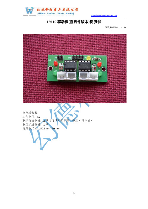

SDS-B048-015-2023型无刷电机驱动板使用说明书1概述SDS-B048-015-2023型无刷电机驱动板(以下简称驱动板)用于单轴转台三相无刷力矩电机直驱控制。
机械安装要求无刷电机和旋变机械上联轴安装,驱动板上集成1路双通道旋变解码功能。
2技术指标额定电压:48V连续堵转电流:≤15A峰值堵转电流:≤30A2.1驱动板2.1.1技术要求环境适应性要求:-40℃~70℃,相对湿度:~90%RH;2.1.2设计指标电源输入:直流48V母线电流:提供母线电压和电流采集功能;输出电流:额定15A,峰值30A;旋变接口:1路双通道旋变接口,励磁频率2000Hz,变压比为0.5;增量式编码器接口:1路通用增量式编码器接口,+5V、GND、A±、B±、Z±、U±、V ±、W±(预留);电机接口:1路三相无刷电机(U、V、W);通讯接口:1路RS422/隔离,波特率不小于2Mbps;通讯接口:1路CAN/隔离,波特率不小于1Mbps;调试接口:2路RS485接口;电机制动器控制接口:1路(驱动能力不小于1A,预留);外部制动电阻接口:1路(驱动能力不小于15A,预留);包络尺寸:长135mm宽85mm高40mm。
驱动板分为功率板和信号板组成,两块板子通过板间连接器板对板对插,组合完成后,功率板在下方,信号板在上方。
功率板最下方有功率器件需要贴在金属上散热。
3电气交联关系3.1连接器接口3.1.1电源接口J3电路板上插座型号为:J30J-02P020S000W,2P 大电流电连接器接点号接点定义信号内容信号方向备注2/B +48V +48V 电源输入输入电源输入1/A+48V_G电源地公共3.1.2抱闸和制动接口J1电路板上插座型号为:J30J-04P040S000W,4P 大电流电连接器接点号接点定义信号内容信号方向备注1/A ZDDZ+制动电阻正端输出制动电阻2/B ZDDZ-制动电阻负端公共3/C ZDQ+抱闸器正端输出电机抱闸器4/DZDQ-抱闸器负端公共3.1.3通讯接口J9电路板上插座型号为:J30J-21TJW-J 接点号接点定义信号内容信号方向备注2RS422R+RS422接收信号+输入RS422通讯控制接口SCIA 1RS422R-RS422接收信号-输入13RS422T+RS422发送信号+输出12RS422T-RS422发送信号-输出3RS422G RS422信号地公共141CANH CAN 通讯信号+双向CAN 通讯控制接口CANA/隔离151CANL CAN 通讯信号-双向4GANG CAN 通讯信号地公共171RS485A 1RS485通讯信号+/A 双向RS485通讯接口SCIC/非隔离161RS485B 1RS485通讯信号-/B 双向5DGND RS485通讯信号地公共RS485通讯信号地192RS485A 2RS485通讯信号+/A 双向RS485通讯接口SCIB/非隔离182RS485B 2RS485通讯信号-/B 双向72CANH CAN 通讯信号+双向CAN 通讯控制接口CANB/预留62CANL CAN 通讯信号-双向9DGND 信号地公共升级跳线8BOOT 升级跳线输入10、20+12V +12V 控制板电源正端输入/输出控制板调试电源(内部预留)11、21+12V_G+12V 控制板电源地公共3.1.4电机接口J2板上插座型号为:J30J-03P030S000W,3P大电流电连接器。

M542H(低成本 4.5A,80V)256细分步进驱动器使用手册Version1.0版权所有不得翻印【使用前请仔细阅读本手册,以免损坏驱动器】宁波纳川自动化科技有限公司M542H步进电机驱动器使用说明在使用本品前,请仔细阅读本使用说明书请妥善保管本说明书,以备日后参考本册外观图片仅供参考,请以实物为准安全注意事项本产品为直流电源供电,请确认电源正负极正确后上电。
请勿带电插拔连接线缆。
此产品非密封,请勿在内部混入镙丝、金属屑等导电性异物或可燃性异物,储存和使用时请注意防潮防湿。
驱动器为功率设备,尽量保持工作环境的散热通风。
在连上步进电机,调节好电流后使其连续工作半小时后观察步进电机是否在额定温度后方可进行后续使用,如果电机温度过高请联系制造商。
一、产品简介1.1 产品特点⏹平均电流控制,两相正弦电流驱动输出⏹供电电压可达80VDC⏹输出电流峰值可达4.5A(均值3.2A)⏹静止时电流自动减半⏹可驱动4,6,8线两相、四相步进电机⏹高速光耦隔离信号输入,脉冲响应频率最高可达300KHZ⏹抗高频干扰能力强⏹输出电流1.5A~4.5A。
⏹输出电流设定方便⏹小巧精美外形尺寸(118*75.5*33mm);⏹细分精度2,4,8,16, 32, 64, 128, 256, 5, 10, 25, 50, 100, 125, 250 细分;⏹有过压、欠压、过流、相间短路保护功能1.2 应用领域适合各种中小型自动化设备和仪器,例如:雕刻机、打标机、切割机、激光照排、绘图仪、数控机床、拿放装置等。
在用户期望低成本、小噪声、高速度的设备中效果特佳。
二、电气、机械和环境指标2.1 电气指标说明 M542H最小值 典型值 最大值 单位 输出电流 1.5 - 4.5(均值3A) A 输入电源电压 18 50~80 120(含纹波)VDC 逻辑输入电流 7 10 16 mA 步进脉冲频率 0 - 300 KHZ 绝缘电阻500M Ω2.2 使用环境及参数冷却方式自然冷却使用环境场合 尽量避免粉尘、油雾及腐蚀性气体环境温度0℃-+50℃ 最高工作温度70℃湿度 40-90% RH9 (不能结露和有水珠)震动 5.9m/S2 Max 保存温度 -20℃-125℃ 重量约280克2.3 机械安装图 单位:毫米※:推荐采用侧面安装,散热效果更佳三、驱动器接口及接线介绍:3.1:弱电接线信号接口描述3.2:强电接口描述3.3输入接口描述M542H 内置高速光电耦合器,允许接收长线控制器,集电极开路和PNP 输出电路的信号。
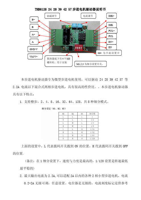
THB6128 24 28 39 42 57步进电机驱动器说明书本步进电机驱动器专为微型步进电机使用,可以驱动24 28 39 42 57等2.2A 电流以下混合式两相步进电机,具有很高的性价比。
本步进电机驱动器具有以下特点:1. 支持整步,2、4、8、16、32、64、128、共8种细分模式。
上面的设置中,L 代表拨码开关拨到ON 的位置,H 代表拨码开关拨到OFF 的位置.(备注:在1细分设置下,速度与力度是最高的,1/128设置是转速最低最平稳的)2. 最大输出电流为2.2A,可以适配2A 以内的各种2相小型步进电机,电流0.2-2A 无级可调,任意设置。
电位器是无级的,电流刻度标记是供参考用的。
如果你的电机是0.5A的调到0.4A与0.6A刻度的中间即可。
3.输入工作电压为DC9-32V.配有电源指示灯。
4.输入电路有防电源接反设计,更安全。
5.有自动半流开/关功能,工作方式更多样。
为开关M4设置。
6.有衰减模式控制功能。
在匹配不同型号的步进电机时,可以控制在不同的工作方式,使电机工作的更稳定,噪声,震动控制到最小。
为靠近LED 指示灯位置的电位器设置。
匹配电机时,调该电位器,使电机的震动与噪声最小即可。
7.行业标准的输入输出接口,兼容性强,可以支持共阴或共阳接法。
8.配有大型散热器,与安装固定柱,螺丝,使用更方便。
注意事项:1.驱动器匹配的电源容量最少都要有2A以上。
否则工作不稳定。
2.电机线不得AB相线交叉接,否则烧驱动器。
3.配PLC使用时,要加串2K左右限流电阻,否则烧驱动器。
附录:步进电机驱动使用注意事项1.关于电机驱动器电源的选用:每个驱动器的工作电源必须大于驱动器的最大驱动电流安数以上的容量。
平时工作作电流一般不是很大。
但电机在换向与启动时,一般电流会提升3-4倍左右或以上,视电机负载而定。
在选用电源时,要选用大容量的,浪涌冲击能力好的电源。
尽量选用开关电源供电。
在要求稳定性高的场合,不建议使用没有稳压功能的工频变压器整流滤波后的电源供电,因为这样会给步进电机的正常工作带来很多不稳定因素。

DRV8825 Stepper Motor Driver Carrier, High CurrentDRV8824/DRV8825 stepper motor drivercarrier with dimensions.OverviewThis product is a carrier board or breakout board for TI’s DRV8825 stepper motor driver; we therefore recommend careful reading of the DRV8825 datasheet (1MB pdf) before using this product. This stepper motor driver lets you control one bipolar stepper motor at up to 2.2 A output current per coil (see the Power Dissipation Considerations section below for more information). Here are some of the driver’s key features:Simple step and direction control interfaceSix different step resolutions: full-step, half-step, 1/4-step, 1/8-step, 1/16-step, and1/32-stepAdjustable current control lets you set the maximum current output with a potentiometer, which lets you use voltages above your stepper motor’s rated voltage to achieve higher step ratesIntelligent chopping control that automatically selects the correct current decaymode (fast decay or slow decay)45 V maximum supply voltageBuilt-in regulator (no external logic voltage supply needed)Can interface directly with 3.3 V and 5 V systemsOver-temperature thermal shutdown, over-current shutdown, and under-voltage lockoutShort-to-ground and shorted-load protection4-layer, 2 oz copper PCB for improved heat dissipationExposed solderable ground pad below the driver IC on the bottom of the PCBModule size, pinout, and interface match those of our A4988 stepper motor driver carriers in most respects (see the bottom of this page for more information)We also carry a DRV8824 stepper motor driver carrier that can serve as a direct substitute for the DRV8825 carrier when using lower-current stepper motors. The DRV8824 can only deliver up to 0.75 A per coil without a heat sink (1.2 A max with proper cooling), but it has larger current-sense resistors that allow for better microstepping performance than the DRV8825 carrier at low currents. The only way to tell our DRV8824 carrier apart from the DRV8825 carrier is by the markings on thedriver IC; if you have a mix of the two, you might consider marking them (there is a blank square on the bottom silkscreen you can use for this). For lower-voltage applications, consider our pin-compatible DRV8834 carrier, which works with motor supply voltages as low as 2.5 V.This product ships with all surface-mount components—including the DRV8825 driver IC—installed as shown in the product picture.Some unipolar stepper motors (e.g. those with six or eight leads) can be controlled bythis driver as bipolar stepper motors. For more information, please see the frequentlyasked questions. Unipolar motors with five leads cannot be used with this driver.Included hardwareThe DRV8825 stepper motor driver carrier ships with one 1×16-pin breakaway 0.1" male header. The headers can be soldered in for use with solderless breadboards or 0.1" female connectors. You can also solder your motor leads and other connections directly to the board.Caution: Installing the header pins so that the silkscreen side is up and the componentsare down can limit the range of motion of the trimpot used to set the current limit. If youplan on installing the header pins in this orientation, please set the current limit beforesoldering in the pins.Using the driverMinimal wiring diagram for connecting a microcontroller to a DRV8824/DRV8825 stepper motor drivercarrier (full-step mode).Power connectionsThe driver requires a motor supply voltage of 8.2 – 45 V to be connected across VMOT and GND. This supply should have appropriate decoupling capacitors close to the board, and it should be capable of delivering the expected stepper motor current.Warning: This carrier board uses low-ESR ceramic capacitors, which makes itsusceptible to destructive LC voltage spikes, especially when using power leads longerthan a few inches. Under the right conditions, these spikes can exceed the 45 Vmaximum voltage rating for the DRV8825 and permanently damage the board, evenwhen the motor supply voltage is as low as 12 V. One way to protect the driver from such spikes is to put a large (at least 47 µF) electrolytic capacitor across motor power (VMOT) and ground somewhere close to the board.Motor connectionsFour, six, and eight-wire stepper motors can be driven by the DRV8825 if they are properly connected; a FAQ answer explains the proper wirings in detail.Warning: Connecting or disconnecting a stepper motor while the driver is powered candestroy the driver. (More generally, rewiring anything while it is powered is asking fortrouble.)Step (and microstep) sizeStepper motors typically have a step size specification (e.g. 1.8° or 200 steps per revolution), which applies to full steps. A microstepping driver such as the DRV8825 allows higher resolutions by allowing intermediate step locations, which are achieved by energizing the coils with intermediate current levels. For instance, driving a motor in quarter-step mode will give the 200-step-per-revolution motor 800 microsteps per revolution by using four different current levels.The resolution (step size) selector inputs (MODE0, MODE1, and MODE2) enable selection from the six step resolutions according to the table below. All three selector inputs have internal 100kΩpull-down resistors, so leaving these three microstep selection pins disconnected results in full-step mode. For the microstep modes to function correctly, the current limit must be set low enough (see below) so that current limiting gets engaged. Otherwise, the intermediate current levels will not be correctly maintained, and the motor will skip microsteps.MODE0MODE1MODE2Microstep ResolutionLow Low Low Full stepHigh Low Low Half stepLow High Low1/4 stepHigh High Low1/8 stepLow Low High1/16 stepHigh Low High1/32 stepLow High High1/32 stepHigh High High1/32 stepControl inputsEach pulse to the STEP input corresponds to one microstep of the stepper motor in the direction selected by the DIR pin. These inputs are both pulled low by default through internal 100kΩ pull-down resistors. If you just want rotation in a single direction, you can leave DIR disconnected.The chip has three different inputs for controlling its power states: R ESET, SLEEP, and ENBL. For details about these power states, see the datasheet. Please note that the driver pulls the SLEEP pin low through an internal 1MΩ pull-down resistor, and it pulls the RESET and ENBL pins low through internal 100kΩ pull-down resistors. These default RESET and SLEEP states are ones that prevent the driver from operating; both of these pins must be high to enable the driver (they can be connected directly to a logic “high” voltage between 2.2 and 5.25 V, or they can be dynamically controlled via connections to digital outputs of an MCU). The default state of the ENBL pin is to enable the driver, so this pin can be left disconnected.Schematic of nSLEEP and nFAULT pins onDRV8824/DRV8825/DRV8834 carriers.The DRV8825 also features a FAULT output that drives low whenever the H-bridge FETs are disabled as the result of over-current protection or thermal shutdown. The carrier board connects this pin to the SLEEP pin through a 10k resistor that acts as a F AULT pull-up whenever SLEEP is externally held high, so no external pull-up is necessary on the FAULT pin. Note that the carrier includes a 1.5k protection resistor in series with the FAULT pin that makes it is safe to connect this pin directly to a logic voltage supply, as might happen if you use this board in a system designed for the pin-compatible A4988 carrier. In such a system, the 10k resistor between SLEEP and FAULT would then act as a pull-up for SLEEP, making the DRV8825 carrier more of a direct replacement for the A4988 in such systems (the A4988 has an internal pull-up on its SLEEP pin). To keep faults from pulling down the SLEEP pin, any external pull-up resistor you add to the S LEEP pin input should not exceed 4.7k.Current limitingTo achieve high step rates, the motor supply is typically much higher than would be permissible without active current limiting. For instance, a typical stepper motor might have a maximum current rating of 1 A with a 5Ω coil resistance, which would indicate a maximum motor supply of 5 V. Using such a motor with 12 V would allow higher step rates, but the current must actively be limited to under 1 A to prevent damage to the motor.The DRV8825 supports such active current limiting, and the trimmer potentiometer on the board can be used to set the current limit. You will typically want to set the driver’s current limit to be at or below the current rating of your stepper motor. One way to set the current limit is to put the driver into full-step mode and to measure the current running through a single motor coil without clocking the STEP input. The measured current will be 0.7 times the current limit (since both coils are always on and limited to approximately 70% of the current limit setting in full-step mode). Another way to set the current limit is to measure the voltage on the “ref” pin and to calculate the resulting current limit (the current sense resistors are 0.100Ω). The ref pin voltage is accessible on a via that is circled on the bottom silkscreen of the circuit board. The current limit relates to the reference voltage as follows:Current Limit = VREF × 2So, for example, if you have a stepper motor rated for 1 A, you can set the current limit to 1 A by setting the reference voltage to 0.5 V.Note: The coil current can be very different from the power supply current, so youshould not use the current measured at the power supply to set the current limit. Theappropriate place to put your current meter is in series with one of your stepper motorcoils.Power dissipation considerationsThe DRV8825 driver IC has a maximum current rating of 2.5 A per coil, but the current sense resistors further limit the maximum current to 2.2 A, and the actual current you can deliver depends on how well you can keep the IC cool. The carrier’s printed circuit board is designed to draw heat out of the IC, but to supply more than approximately 1.5 A per coil, a heat sink or other cooling method is required.This product can get hot enough to burn you long before the chip overheats. Take carewhen handling this product and other components connected to it.Please note that measuring the current draw at the power supply will generally not provide an accurate measure of the coil current. Since the input voltage to the driver can be significantly higher than the coil voltage, the measured current on the power supply can be quite a bit lower than the coil current (the driver and coil basically act like a switching step-down power supply). Also, if the supply voltage is very high compared to what the motor needs to achieve the set current, the duty cycle will be very low, which also leads to significant differences between average and RMS currents. Additionally, please note that the coil current is a function of the set current limit, but it does not necessarily equal the current limit setting. The actual current through each coil changes with each microstep. See the DRV8825 datasheet for more information.Schematic diagramSchematic diagram for the DRV8824/DRV8825 stepper motor driver carrier.The current sense resistors (R2 and R3) on the DRV8825 carrier are 0.100 Ω. This schematic is also available as a downloadable pdf (196k pdf).Key differences between the DRV8825 and A4988The DRV8825 carrier was designed to be as similar to our A4988 stepper motor driver carriers as possible, and it can be used as a drop in replacement for the A4988 carrier in many applications because it shares the same size, pinout, and general control interface. There are a few differences between the two modules that should be noted, however:DRV8825 stepper motor drivercarrier.A4988 stepper motor drivercarrier, Black EditionThe pin used to supply logic voltage to the A4988 is used as the DRV8825’s FAULT output, since the DRV8825 does not require a logic supply (and the A4988 does not have a fault output). Note that it is safe to connect the FAULT pin directly to a logic supply (there is a 1.5k resistor between the IC output and the pin to protect it), so the DRV8825 module can be used in systems designed for the A4988 that route logic power to this pin.The SLEEP pin on the DRV8825 is not pulled up by default like it is on the A4988, but the carrier board does connect it to the FAULT pin through a 10k resistor. Therefore, systems intended for the A4988 that route logic power to the FAULT pin will effectively have a 10k pull-up on the SLEEP pin. (This 10k resistor is not present on the initial(md20a) version of the DRV8825 carrier.)The current limit potentiometer is in a different location.The relationship between the current limit setting and the reference pin voltage is different.The DRV8825 offers 1/32-step microstepping; the A4988 only goes down to 1/16-step.The mode selection pin inputs corresponding to 1/16-step on the A4988 result in 1/32-step microstepping on the DRV8825. For all other microstepping resolutions, the step selection table is the same for both the DRV8825 and the A4988.The timing requirements for minimum pulse durations on the STEP pin are different for the two drivers. With the DRV8825, the high and low STEP pulses must each be at least 1.9 us; they can be as short as 1 us when using the A4988.The DRV8825 has a higher maximum supply voltage than the A4988 (45 V vs 35 V), which means the DRV8825 can be used more safely at higher voltages and is less susceptible to damage from LC voltage spikes.The DRV8825 can deliver more current than the A4988 without any additional cooling (based on our full-step tests: 1.5 A per coil for the DRV8825 vs 1.2 A per coil for theA4988 Black Edition and 1 A per coil for the original A4988 carrier).The DRV8825 uses a different naming convention for the stepper motor outputs, but they are functionally the same as the corresponding pins on the A4988 carrier, so the same connections to both drivers result in the same stepper motor behavior. On both boards, the first part of the label identifies the coil (so you have coils “A” and “B” on the DRV8825 and coils “1” and “2” on the A4988).For those with color-sensitive applications, note that the DRV8825 carrier is purple. In summary, the DRV8825 carrier is similar enough to our A4988 carriers that the minimum connection diagram for the A4988 is a valid alternate way to connect the DRV8825 to a microcontroller as well:Alternative minimal wiring diagram for connecting a microcontroller to a DRV8824/DRV8825 steppermotor driver carrier (full-step mode).Documentation on producer website.。

前言本款产品适合驱动持续工作电流在10A以下、额定电压范围在12V~40V之间的任何一款三相直流无刷霍尔电机。
具有免维护、长寿命、低速下总能保持最大转矩等优势。
本产品广泛应用于针织设备、医疗设备、食品机械、电动工具、园林机械、智能家居等电气自动化控制领域。
本手册阐述了该驱动器的的功能、安装、调试、维护、运行等方面的内容。
使用产品前,请认真阅读本手册并熟知本产品的安全注意事项。
在使用本款产品时,若有疑问,请仔细查阅产品说明书或致电我公司售后服务部,我们将竭诚为您服务。
安全注意事项警示标志:危险:表示该操作错误可能危及人身安全!注意:表示该操作错误可能导致设备损坏!注意事项:安装:防止灰尘、腐蚀性气体、导电物体、液体及易燃物侵入,并保持良好的散热条件。
接线:请由专业人员仔细阅读完使用说明之后进行接线作业;接线必须在电源断开的状态下进行,防止电击。
通电前:接通电源前检查并保证接线的准确无误;请确认输入电源与驱动器的额定工作电压及极性是否一致;通电中:驱动器接通电源后,请勿直接接触输出端子,有的端子上有高电压,非常危险;请确保在驱动器指示灯熄灭后再对驱动器的接线端子进行插拔;请勿对驱动器随意进行耐高压与绝缘性能试验;请勿将电磁接触器、电磁开关接到输出回路。
目录前言 (1)安全注意事项 (2)目录 (3)一.概述 (5)1.型号说明 (5)2.功能参数 (5)3.功能特点 (6)二.端口说明 (7)1.接口定义 (7)2.接线示意图 (8)3.安装尺寸 (9)三.功能与使用 (10)1.出厂说明 (10)2.操作步骤说明 (10)2.1外置电位器调速 (11)2.2外部电压调速 (11)2.3外部PWM信号调速 (11)2.4CAN总线控制 (11)3.功能端子说明 (12)3.1F/R端子:正反转功能 (12)3.2EN端子:使能功能 (12)3.3BRK端子:刹车抱死功能 (12)3.4SV端子:外部调速端子 (13)3.5PG端子:电机转速信号输出 (13)3.6ALM端子:报警输出 (13)3.7PWR/ALM:指示灯 (14)一.概述本款驱动器适用于对直流无刷有霍尔电机进行转速控制,其最大的优点是在低速时总能控制电机保持最大转矩。
原版操作手册的译本© 2020 Festo SE & Co. KG 保留一切权利1适用文件有关产品的所有文件 è/sp 产品的用户文件使用手册EMCA-EC-DIO-…设备及功能说明书;装配、安装、调试和诊断使用手册EMCA-EC-C-HP-…设备配置文件 FHPP (Festo Handling and Positioning Profile)的说明FCT 插件帮助EMCAFesto Configuration Tool (FCT) 的在线帮助,用于调试和参数设置专项文件EMCA-EC_UL-…根据 Underwriters Laboratories Inc. (UL) 认证在美国和加拿大使用本产品的要求Tab. 12安全–务必注意遵守产品相关文件和其它所用部件文件中的安全和警告注意事项。
–进行装配和安装工作之前,关闭供电电压并采取保护措施,防止其意外重新启动。
在彻底完成装配和安装工作之后,才能重新接通电源。
–禁止在带电情况下插拔插头。
–遵守有关静电敏感部件的操作规程。
–只有当正确安装驱动器并完成全部参数配置之后,才能启用控制器。
–不允许对本设备进行维修。
若损坏,则更换设备。
–除了外壳盖上的 4 颗螺钉,不得松开其他螺钉。
触碰炙热表面有烫伤危险。
接触壳体可能导致烫伤。
由此可能造成人员惊慌,并作出失控反应。
这还可能造成其他损失。
•避免意外触碰壳体。
•告知操作人员和维护人员可能存在的危险。
•进行维修工作之前:使驱动器冷却到 40 °C 以下。
快速旋转的电机轴具有较高的扭矩。
接触电机轴,可能会造成烫伤和擦伤。
•确保不会接触到旋转的电机轴和其上安装的部件。
产生气体,存在火灾危险。
清洁剂与驱动器的高温表面发生接触,可能会产生气体并着火。
•进行清洁工作之前,使驱动器冷却到室温。
2.1按规定使用按照规定,本产品用于驱动和控制机电驱动器。
本产品设计用于安装在机器中。
仅允许在以下情况下使用:–在技术性能完好的状态下–在未作擅自修改的初始状态下;仅允许使用产品随附文件中的扩展–在本产品技术参数规定的极限值内–在工业领域内除工业环境外,例如在商业和住宅混合区等,必须采取措施防止无线电干扰。
DP801车驱动板使用说明一、简介:DP801车驱动板(以下简称:驱动板),是针对使用DP801单片机学习机,基于微型直流电机控制的小车或机器人实验所开发的。
驱动板通过I/O口接收DP801单片机学习板的控制命令,并根据命令控制电机的运行状态。
驱动板通过电机驱动电路可控制两路各2个直流电机,每路的2个电机最大总驱动电流可达2A。
二、驱动板介绍:驱动板外观图驱动板有4个端子,分别与DP801、传感器电路板连接,并对外提供电源输出口,各端子功能在下面介绍。
驱动板右下角是电源输入端和电源开关;电阻R8、R9、R6、R7可以用来调整电机的速度(仅介绍,不推荐自己调整)1、端子JDP801:与DP801单片机学习机通过一条16P灰排线连接,给DP801提供电源,接收来自学习板的控制命令并进行相应动作,同时将JH1和JH2的红外传感器电路板信号转接给DP801输入0,3,1,5;注意:连接时灰排线的红边,一定要端子的上端(DP801和驱动板都是如此)。
2、传感器端子JH1和JH2:与红外传感器电路板上的两个端子的连接。
端子的左边两位是电源,左负右正,给红外传感器电路板提供电源。
端子的右边两位是信号输入端,分别连接红外传感器电路板的4个红外探头信号输出,并通过JDP801端子转接到DP801的输入0、输入3、输入1、输入5(从左向右),DP801可以根据4路信号进行编程,控制车实现循迹等功能;3、电源端子PWR左边的端子PWR提供4路电源的输出,可以给其他传感器等提供电源。
极性左负右正,电压+5V。
4、电源输入与开关右下角是电源输入端,可以插配套的充电器给电池充电。
插入充电器就可以给电池充电,不需要打开电源开关。
充电器上的指示灯由红色变成绿色,或充电10小时以上可以充满电池的电量。
电源开关拨到“ON”,接通电源。
驱动板的指示灯应该点亮,与驱动板连接的DP801也应该开始通电。
5、对电机的速度微调本项功能不推荐大家来操作,只建议有充分电路知识和调试经验的技术人员进行调整。
LN298电机驱动模块使用说明雁凌电子在使用本产品前,请仔细阅读本使用说明书,这样您在使用中遇到问题时,也许可以通过本说明书就能解决;请妥善保管本说明书,以备日后参考;本册外观图片仅供参考,请以实物为准。
一模块使用前注意事项模块使用前注意事项1、本产品为直流电源供电,请确认电源正负极正确后上电;2、请勿带电插拔连接线缆;3、此产品非密封,请勿在内部混入镙丝、金属屑等导电性异物;4、储存和使用时请注意防潮防湿;5、第一次上电时观察绿色电源指示灯(L5)是否点亮,如果不亮,请立即断电检查电源是否接反。
板上有个5V插针P3,它要配合跳线器P2一起使用,使用时分两种情况:(在第3页有详细介绍)A、如果需要通过电机驱动板插针P3给单片机等系统板供5V电时,将P2跳冒短接即可;B、如果单片机等系统板有自己的5V电源时,此时需要将单片机5V电源接入P3同时一定要把P2跳冒去掉,否则可能会烧坏驱动板板载稳压芯片78M05。
6、驱动器为功率设备,请保持工作环境的散热通风;在连上电机后使其连续工作一段时间后观察电机和驱动芯片的温升正常后方可进行后续使用主要功能特点模块主要功能特点二模块关键芯片:L298N双H桥直流/步进电机驱动芯片L298N芯片工作电压:DC 4.5~5.5V。
电机驱动电源电压DC5--35V。
电源输入正常时有LED灯指示。
最大输出电流2A(瞬间峰值电流3A),最大输出功率25W。
输出正常时电机运转有LED灯指示。
具有二极管续流保护。
可单独控制2台直流电机或1台两相4线(或6线)步进电机。
可以采用并联接法控制一台高达3A的直流电机。
可实现电机正反转。
直流电机转速可通过PWM方式实现调速。
模块尺寸:4.4cm*5.0cm硬件接口说明模块硬件接口说明三模块P3:电机驱动电源输入接口范围DC5V—35V。
V+接正,GND接地,注意不要接反电源极性。
P1:驱动器和控制端的接口控制直流电机时IN1、IN2和ENA为一组,它们控制的电机A接在A+和A-,如果电机A不调速,则ENA悬空即可;如果电机A调速,则ENA接一路PWM输出口;IN3、IN4和ENB为一组,它们控制的电机B接在B+和B-,如果电机B不调速,则ENB悬空即可;如果电机B调速,则ENB接另一路PWM输出口;控制步进电机时IN1、IN2、IN3和IN4接4根IO线,A-、A+接步进电机一相;B-、B+接步进电机另一相。
L298直流电机/步进电机驱动板【实物图片】
驱动板尺寸:65mmX50mmX30mm
安装尺寸:49.2mmX45mm 孔径:直径3.5mm
[主要功能特点]
关键芯片:L298N 双H 桥直流/步进电机驱动芯片
L298N 芯片工作电压:DC 4.5~5.5V。
电机驱动电源电压DC 5--35V。
电源输入正常时有LED 灯指示。
最大输出电流2A(瞬间峰值电流3A),最大输出功率25W。
输出正常时电机运转有LED 灯指示。
具有二极管续流保护。
可单独控制2台直流电机或1台两相4 线(或6 线)步进电机。
可以采用并联接法控制一台高达3A 的直流电机。
可实现电机正反转。
直流电机转速可通过PWM 方式实现调速。
可以给单片机等控制器提供5V电源
接口说明:
J1:电机驱动电源输入接口
范围DC 5V—35V。
V+接正,GND接地,注意不要接反电源极性。
J2:驱动器和控制端的接口
控制直流电机时IN1、IN2 和ENA 为一组,它们控制的电机A 接在J3 的A+和A-,如果电机A 不调速,则ENA 悬空即可;如果电机A调速,则ENA 接一路PWM 输出口;IN3、IN4 和ENB 为一组,它们控制的电机B 接在J3 的B+和B-,如果电机B 不调速,则ENB 悬空即可;如果电机B 调速,则ENB 接另一路PWM 输出口;控制步进电机时IN1、IN2、IN3和IN4接4根IO 线,A-、A+接步进电机一相;B-、B+接步进电机另一相。
ENA、ENB 悬空即可。
如果是6线步进电机,可以把两相的公共线一起接在 J1 的V+即可。
J3:输出电机接口
接直流电机时,A+和A-为一路电机;B+和B-为另一路电机。
接步进电机时,A+、A-、B+和B-步进电机的4 根相线接口,如果是6线步进电机,可以把两相的公共线一起接在 J1 的V+即可。