步进电机驱动器说明书
- 格式:doc
- 大小:23.50 KB
- 文档页数:2
步进电机驱动器说明书DHBQ30722是基于DSP控制的三相步进电机驱动器。
它是将先进的DSP控制芯⽚和三相逆变驱动模块结合⼀起所构成的新⼀代数字步进电机驱动器。
驱动电压为AC110V-220V,适配电流在7.0A以下、外径57-130mm的各种型号的三相混合式步进电机。
该驱动器内部采⽤类似伺服控制原理的电路,此电路可以使电机运⾏平稳,⼏乎没有震动和噪⾳,电机在⾼速时,⼒矩⼤⼤⾼于⼆相和五相混合式步进电机。
定位精度最⾼可达60000步/转。
该产品⼴泛应⽤于雕刻机、中型数控机床、电脑绣花机、包装机械等分辨率较⾼的⼤、中型数控设备上。
特●⾼性能、低价格●设有16档等⾓度恒⼒矩细分,最⾼分辨率60000步/转●最⾼反应频率可达200Kpps●步进脉冲停⽌超过1.5s时,线圈电流⾃动减到设定电流的⼀半●光电隔离信号输⼊/输出●驱动电流1.2A/相到7.0A/相分16档可调●单电源输⼊,电压范围:AC110V-220V●相位记忆功能(注:输⼊停⽌超过3秒后,驱动器⾃动记忆当时电机相位,重新上电或MF信号由低电平变为⾼电平时,驱动器⾃动恢复电机相位)。
电流设定驱动器⼯作电流由DIP-1端⼦设定,运⾏电流为正常⼯作输出电流设置开关(详见下表)运⾏电流(A) 1.2 1.5 2.0 2.3 2.5 3.0 3.2 3.6 D1OFF OFF OFF OFF OFF OFF OFF OFF D2OFF OFF OFF OFF ON ON ON ON D3OFF OFF ON ON OFF OFF ON ON D4OFF ON OFF ON OFF ON OFF ON运⾏电流(A) 4.0 4.5 5.0 5.3 5.8 6.2 6.57.0 D1ON ON ON ON ON ON ON ON D2OFF OFF OFF OFF ON ON ON OND3OFF OFF ON ON OFF OFF ON ON D4OFF ON OFF ON OFF ON OFF ON细分设定驱动器细分由DIP-2端⼦设定,共16档,由6位拨码开关的前四位分别设定(后两位为功能设定)。
MS3540MI步进电机驱动器使用手册MS3540MI步进电机驱动器使用手册1. 产品简介1.1 概述MS3540MI为智能型双极细分型步进电机驱动器。
该驱动器集成了运动控制功能,可使用Mis可编程软件通过RS232接口下载程序;也可使用SCL语言通过PC、PLC或MCU实现对驱动器及电机的实时控制。
驱动器上的可编程的输入、输出接口用于和外部开关、传感器等其它元件进行同步,在简单的运动控制中可将该驱动器作为控制器使用,减少了系统元件的数量,降低了系统集成的复杂度和成本。
1.2 特点•12-42V 直流电压供电•0.2-3.5A 相电流(峰值),通过软件配置•自动减流功能,通过软件配置•13 种细分选择,通过软件配置••8 个可编程的光电隔离输入信号端口3 个可编程的光电隔离输出信号端口MS3540MI步进电机驱动器使用手册电机•驱动器•齿轮箱•开关电源- 1 - •双极性PWM 恒流斩波控制,开关频率20-30kHz•人机交互界面(MSMMI)配件可选•利用Mis 编程软件方便地对驱动器进行编程,使其独立实现运动控制功能•利用SCL 驱动器编程语言,可以实现驱动器与PC、PLC 或MCU 的连接,以对驱动器进行实时控制操作•通过Mis 网络集线器可以使驱动器与其它的Mis 系列驱动器进行网络互连,实现- 2 -MS3540MI步进电机驱动器使用手册一台主机同时控制多台驱动器的功能输入输出2. 功能框图MS3540MI步进电机驱动器使用手册5-24V 信号,光电隔离输入。
2200ohms 内部电阻。
(可采用下拉(NPN)或上拉(PNP)控制信号电路)光电隔离。
光敏三极管C、E 间最大电压24V,最大输出电流100 mA。
细分13 种细分选择可通过软件配置。
如采用 1.8˚电机,则每圈转动步数:2000, 5000, 10000, 12800, 18000, 20000, 21600,25000,25400, 25600, 36000, 50000, 50800.运动刷新频率12800Hz.物理特性装在黑色阳极氧化的铝散热底盘上。
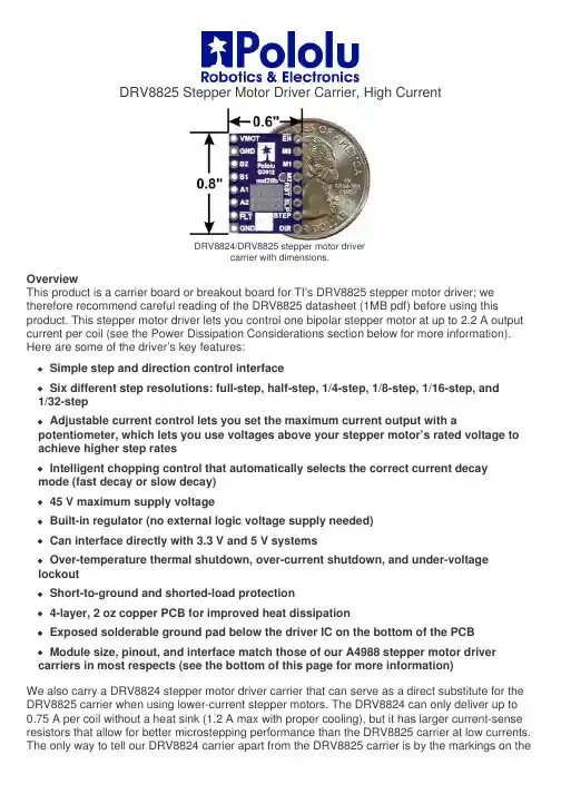
DRV8825 Stepper Motor Driver Carrier, High CurrentDRV8824/DRV8825 stepper motor drivercarrier with dimensions.OverviewThis product is a carrier board or breakout board for TI’s DRV8825 stepper motor driver; we therefore recommend careful reading of the DRV8825 datasheet (1MB pdf) before using this product. This stepper motor driver lets you control one bipolar stepper motor at up to 2.2 A output current per coil (see the Power Dissipation Considerations section below for more information). Here are some of the driver’s key features:Simple step and direction control interfaceSix different step resolutions: full-step, half-step, 1/4-step, 1/8-step, 1/16-step, and1/32-stepAdjustable current control lets you set the maximum current output with a potentiometer, which lets you use voltages above your stepper motor’s rated voltage to achieve higher step ratesIntelligent chopping control that automatically selects the correct current decaymode (fast decay or slow decay)45 V maximum supply voltageBuilt-in regulator (no external logic voltage supply needed)Can interface directly with 3.3 V and 5 V systemsOver-temperature thermal shutdown, over-current shutdown, and under-voltage lockoutShort-to-ground and shorted-load protection4-layer, 2 oz copper PCB for improved heat dissipationExposed solderable ground pad below the driver IC on the bottom of the PCBModule size, pinout, and interface match those of our A4988 stepper motor driver carriers in most respects (see the bottom of this page for more information)We also carry a DRV8824 stepper motor driver carrier that can serve as a direct substitute for the DRV8825 carrier when using lower-current stepper motors. The DRV8824 can only deliver up to 0.75 A per coil without a heat sink (1.2 A max with proper cooling), but it has larger current-sense resistors that allow for better microstepping performance than the DRV8825 carrier at low currents. The only way to tell our DRV8824 carrier apart from the DRV8825 carrier is by the markings on thedriver IC; if you have a mix of the two, you might consider marking them (there is a blank square on the bottom silkscreen you can use for this). For lower-voltage applications, consider our pin-compatible DRV8834 carrier, which works with motor supply voltages as low as 2.5 V.This product ships with all surface-mount components—including the DRV8825 driver IC—installed as shown in the product picture.Some unipolar stepper motors (e.g. those with six or eight leads) can be controlled bythis driver as bipolar stepper motors. For more information, please see the frequentlyasked questions. Unipolar motors with five leads cannot be used with this driver.Included hardwareThe DRV8825 stepper motor driver carrier ships with one 1×16-pin breakaway 0.1" male header. The headers can be soldered in for use with solderless breadboards or 0.1" female connectors. You can also solder your motor leads and other connections directly to the board.Caution: Installing the header pins so that the silkscreen side is up and the componentsare down can limit the range of motion of the trimpot used to set the current limit. If youplan on installing the header pins in this orientation, please set the current limit beforesoldering in the pins.Using the driverMinimal wiring diagram for connecting a microcontroller to a DRV8824/DRV8825 stepper motor drivercarrier (full-step mode).Power connectionsThe driver requires a motor supply voltage of 8.2 – 45 V to be connected across VMOT and GND. This supply should have appropriate decoupling capacitors close to the board, and it should be capable of delivering the expected stepper motor current.Warning: This carrier board uses low-ESR ceramic capacitors, which makes itsusceptible to destructive LC voltage spikes, especially when using power leads longerthan a few inches. Under the right conditions, these spikes can exceed the 45 Vmaximum voltage rating for the DRV8825 and permanently damage the board, evenwhen the motor supply voltage is as low as 12 V. One way to protect the driver from such spikes is to put a large (at least 47 µF) electrolytic capacitor across motor power (VMOT) and ground somewhere close to the board.Motor connectionsFour, six, and eight-wire stepper motors can be driven by the DRV8825 if they are properly connected; a FAQ answer explains the proper wirings in detail.Warning: Connecting or disconnecting a stepper motor while the driver is powered candestroy the driver. (More generally, rewiring anything while it is powered is asking fortrouble.)Step (and microstep) sizeStepper motors typically have a step size specification (e.g. 1.8° or 200 steps per revolution), which applies to full steps. A microstepping driver such as the DRV8825 allows higher resolutions by allowing intermediate step locations, which are achieved by energizing the coils with intermediate current levels. For instance, driving a motor in quarter-step mode will give the 200-step-per-revolution motor 800 microsteps per revolution by using four different current levels.The resolution (step size) selector inputs (MODE0, MODE1, and MODE2) enable selection from the six step resolutions according to the table below. All three selector inputs have internal 100kΩpull-down resistors, so leaving these three microstep selection pins disconnected results in full-step mode. For the microstep modes to function correctly, the current limit must be set low enough (see below) so that current limiting gets engaged. Otherwise, the intermediate current levels will not be correctly maintained, and the motor will skip microsteps.MODE0MODE1MODE2Microstep ResolutionLow Low Low Full stepHigh Low Low Half stepLow High Low1/4 stepHigh High Low1/8 stepLow Low High1/16 stepHigh Low High1/32 stepLow High High1/32 stepHigh High High1/32 stepControl inputsEach pulse to the STEP input corresponds to one microstep of the stepper motor in the direction selected by the DIR pin. These inputs are both pulled low by default through internal 100kΩ pull-down resistors. If you just want rotation in a single direction, you can leave DIR disconnected.The chip has three different inputs for controlling its power states: R ESET, SLEEP, and ENBL. For details about these power states, see the datasheet. Please note that the driver pulls the SLEEP pin low through an internal 1MΩ pull-down resistor, and it pulls the RESET and ENBL pins low through internal 100kΩ pull-down resistors. These default RESET and SLEEP states are ones that prevent the driver from operating; both of these pins must be high to enable the driver (they can be connected directly to a logic “high” voltage between 2.2 and 5.25 V, or they can be dynamically controlled via connections to digital outputs of an MCU). The default state of the ENBL pin is to enable the driver, so this pin can be left disconnected.Schematic of nSLEEP and nFAULT pins onDRV8824/DRV8825/DRV8834 carriers.The DRV8825 also features a FAULT output that drives low whenever the H-bridge FETs are disabled as the result of over-current protection or thermal shutdown. The carrier board connects this pin to the SLEEP pin through a 10k resistor that acts as a F AULT pull-up whenever SLEEP is externally held high, so no external pull-up is necessary on the FAULT pin. Note that the carrier includes a 1.5k protection resistor in series with the FAULT pin that makes it is safe to connect this pin directly to a logic voltage supply, as might happen if you use this board in a system designed for the pin-compatible A4988 carrier. In such a system, the 10k resistor between SLEEP and FAULT would then act as a pull-up for SLEEP, making the DRV8825 carrier more of a direct replacement for the A4988 in such systems (the A4988 has an internal pull-up on its SLEEP pin). To keep faults from pulling down the SLEEP pin, any external pull-up resistor you add to the S LEEP pin input should not exceed 4.7k.Current limitingTo achieve high step rates, the motor supply is typically much higher than would be permissible without active current limiting. For instance, a typical stepper motor might have a maximum current rating of 1 A with a 5Ω coil resistance, which would indicate a maximum motor supply of 5 V. Using such a motor with 12 V would allow higher step rates, but the current must actively be limited to under 1 A to prevent damage to the motor.The DRV8825 supports such active current limiting, and the trimmer potentiometer on the board can be used to set the current limit. You will typically want to set the driver’s current limit to be at or below the current rating of your stepper motor. One way to set the current limit is to put the driver into full-step mode and to measure the current running through a single motor coil without clocking the STEP input. The measured current will be 0.7 times the current limit (since both coils are always on and limited to approximately 70% of the current limit setting in full-step mode). Another way to set the current limit is to measure the voltage on the “ref” pin and to calculate the resulting current limit (the current sense resistors are 0.100Ω). The ref pin voltage is accessible on a via that is circled on the bottom silkscreen of the circuit board. The current limit relates to the reference voltage as follows:Current Limit = VREF × 2So, for example, if you have a stepper motor rated for 1 A, you can set the current limit to 1 A by setting the reference voltage to 0.5 V.Note: The coil current can be very different from the power supply current, so youshould not use the current measured at the power supply to set the current limit. Theappropriate place to put your current meter is in series with one of your stepper motorcoils.Power dissipation considerationsThe DRV8825 driver IC has a maximum current rating of 2.5 A per coil, but the current sense resistors further limit the maximum current to 2.2 A, and the actual current you can deliver depends on how well you can keep the IC cool. The carrier’s printed circuit board is designed to draw heat out of the IC, but to supply more than approximately 1.5 A per coil, a heat sink or other cooling method is required.This product can get hot enough to burn you long before the chip overheats. Take carewhen handling this product and other components connected to it.Please note that measuring the current draw at the power supply will generally not provide an accurate measure of the coil current. Since the input voltage to the driver can be significantly higher than the coil voltage, the measured current on the power supply can be quite a bit lower than the coil current (the driver and coil basically act like a switching step-down power supply). Also, if the supply voltage is very high compared to what the motor needs to achieve the set current, the duty cycle will be very low, which also leads to significant differences between average and RMS currents. Additionally, please note that the coil current is a function of the set current limit, but it does not necessarily equal the current limit setting. The actual current through each coil changes with each microstep. See the DRV8825 datasheet for more information.Schematic diagramSchematic diagram for the DRV8824/DRV8825 stepper motor driver carrier.The current sense resistors (R2 and R3) on the DRV8825 carrier are 0.100 Ω. This schematic is also available as a downloadable pdf (196k pdf).Key differences between the DRV8825 and A4988The DRV8825 carrier was designed to be as similar to our A4988 stepper motor driver carriers as possible, and it can be used as a drop in replacement for the A4988 carrier in many applications because it shares the same size, pinout, and general control interface. There are a few differences between the two modules that should be noted, however:DRV8825 stepper motor drivercarrier.A4988 stepper motor drivercarrier, Black EditionThe pin used to supply logic voltage to the A4988 is used as the DRV8825’s FAULT output, since the DRV8825 does not require a logic supply (and the A4988 does not have a fault output). Note that it is safe to connect the FAULT pin directly to a logic supply (there is a 1.5k resistor between the IC output and the pin to protect it), so the DRV8825 module can be used in systems designed for the A4988 that route logic power to this pin.The SLEEP pin on the DRV8825 is not pulled up by default like it is on the A4988, but the carrier board does connect it to the FAULT pin through a 10k resistor. Therefore, systems intended for the A4988 that route logic power to the FAULT pin will effectively have a 10k pull-up on the SLEEP pin. (This 10k resistor is not present on the initial(md20a) version of the DRV8825 carrier.)The current limit potentiometer is in a different location.The relationship between the current limit setting and the reference pin voltage is different.The DRV8825 offers 1/32-step microstepping; the A4988 only goes down to 1/16-step.The mode selection pin inputs corresponding to 1/16-step on the A4988 result in 1/32-step microstepping on the DRV8825. For all other microstepping resolutions, the step selection table is the same for both the DRV8825 and the A4988.The timing requirements for minimum pulse durations on the STEP pin are different for the two drivers. With the DRV8825, the high and low STEP pulses must each be at least 1.9 us; they can be as short as 1 us when using the A4988.The DRV8825 has a higher maximum supply voltage than the A4988 (45 V vs 35 V), which means the DRV8825 can be used more safely at higher voltages and is less susceptible to damage from LC voltage spikes.The DRV8825 can deliver more current than the A4988 without any additional cooling (based on our full-step tests: 1.5 A per coil for the DRV8825 vs 1.2 A per coil for theA4988 Black Edition and 1 A per coil for the original A4988 carrier).The DRV8825 uses a different naming convention for the stepper motor outputs, but they are functionally the same as the corresponding pins on the A4988 carrier, so the same connections to both drivers result in the same stepper motor behavior. On both boards, the first part of the label identifies the coil (so you have coils “A” and “B” on the DRV8825 and coils “1” and “2” on the A4988).For those with color-sensitive applications, note that the DRV8825 carrier is purple. In summary, the DRV8825 carrier is similar enough to our A4988 carriers that the minimum connection diagram for the A4988 is a valid alternate way to connect the DRV8825 to a microcontroller as well:Alternative minimal wiring diagram for connecting a microcontroller to a DRV8824/DRV8825 steppermotor driver carrier (full-step mode).Documentation on producer website.。

三相混合式步进电机驱动器使用说明书1.特点★AC80~220V交流供电,能适应恶劣的电网环境★双极恒相流细分驱动★最大输出驱动电流6A/相(有效值,峰值达8A)★最大30000步/转的十六种细分模式可★过压、过流保护★输入信号光电隔离★可适应共阳、共阴、单/双脉冲多种模式★脱机保持功能★提供节能的自动半电流锁定功能2.性能指标供电电源80V~220VAC,容量0.8KVA输出电流有效值6A/相(峰值可达8A)(输出电流可由面板拨码开关设定)驱动方式恒相流PWM控制励磁方式400步/转,500步/转,600步/转,750步/转,1000步/转1500步/转,2000步/转,2500步/转,3000步/转,3750步/转5000步/转,6000步/转,7500步/转,10000步/转,15000步/转30000步/转绝缘电阻在常温常压下>500MΩ绝缘强度在常温常压下1KV,1分钟3.使用环境及参数冷却方式强制风冷使用环境场合尽量避免粉尘、油雾及腐蚀性气体温度0℃~+50℃湿度<80%RH,无凝露,无结霜震动 5.9m/s2Max保存温度-20℃~+65℃外形尺寸187×116×81mm重量 1.3Kg4.功能及使用★电源电压驱动器内部的开关电源设计保证了其可以适应较宽的电压范围,推荐使用80~220VAC,提高电压对提高电机的高速力矩有效,但是同时会加大运行噪音。
由于电机电磁感应回导致电机外壳生出一定的电荷,为确保使用者安全,请务必使用线径2mm2以上的机壳保护线和驱动器的机壳接地端子与保护大地可靠连接,并采用隔离变压器为驱动器供电★输出电流选择本驱动器采用双极恒流方式,最大输出电流值为6A/相(有效值),通过驱动器侧板第7,8四位开关的不同组合可以方便的选择4种电流值,从2A到6A(详见电流选择表),(注意:这里所说的电流是指驱动器每相输出电流的有效值,使用串电流表的方式不能得到正确的读数。
深圳市研控自动化科技有限公司目录前言 (1)1概述 (2)1.1产品介绍 (2)1.2特性 (2)1.3应用领域 (2)1.4产品命名规则 (3)2性能指标 (4)2.1电气特性 (4)2.2使用环境 (4)3安装 (5)3.1安装尺寸 (5)3.2安装方法 (5)4 驱动器端口与接线 (6)4.1接线示意图 (6)4.2端口定义 (7)4.2.1状态指示灯 (7)4.2.2通讯端口 (7)4.2.3输入/输出端口 (7)4.2.4电源端口 (8)4.2.5拨码开关 (8)4.3输入/输出端口操作 (8)4.4拨码开关设定 (9)5 电机规格及接线 (11)5.1技术规格 (11)5.2电机接线图 (11)6 CANopen协议 (12)6.1 CANopen协议概述 (12)6.1.1 CAN总线与CANopen (12)6.1.2 CANopen功能描述 (12)6.2驱动器控制协议CiA 402 (15)6.2.1 CiA402状态机 (15)6.2.2控制字与状态字 (16)6.2.3工作模式 (17)6.2.4位置模式 (18)6.2.5速度模式 (20)6.2.6回原点模式 (22)7对象字典 (26)8报警排除 (35)9版本修订历史 (36)10保修及售后服务 (37)10.1保修 (37)10.2售后服务 (37)附录1:快速编写运动控制功能块指南 (38)前言感谢您使用本公司总线型步进电机驱动器。
在使用本产品前,请务必仔细阅读本手册,了解必要的安全信息、注意事项以及操作方法等。
错误的操作可能引发极其严重的后果。
声明本产品的设计和制造不具备保护人身安全免受机械系统威胁的能力,请用户在机械系统设计和制造过程中考虑安全防护措施,防止因不当的操作或产品异常造成事故。
由于产品的改进,手册内容可能变更,恕不另行通知。
用户对产品的任何改装我公司将不承担任何责任。
阅读时,请注意手册中的以下标示:注意:提醒您注意文字中的要点。
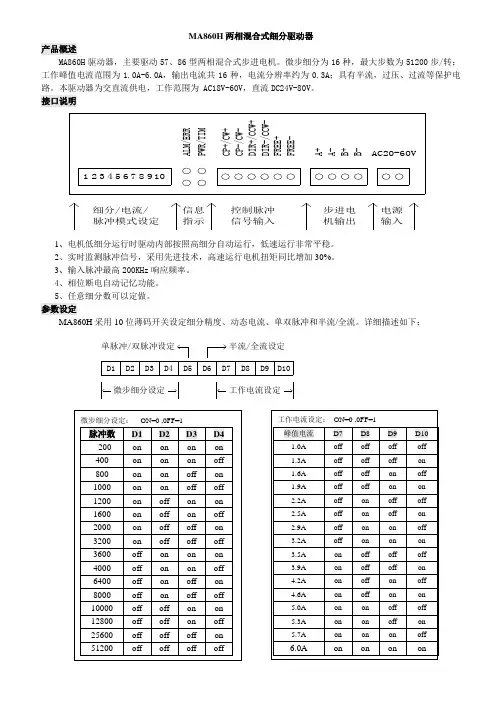
MA860H 两相混合式细分驱动器
产品概述
MA860H 驱动器,主要驱动57、86型两相混合式步进电机。
微步细分为16种,最大步数为51200步/转;工作峰值电流范围为1.0A-6.0A ,输出电流共16种,电流分辨率约为0.3A ;具有半流,过压、过流等保护电路。
本驱动器为交直流供电,工作范围为 AC18V-60V ,直流DC24V-80V 。
接口说明
B
+B -9C P -/C W -A +A -D I R -/C C W -F R E E +D I R +/C C W +F R E E -
P W R /T I M
C P +/C W +
10
A
L M
/E R
R 523
487
61AC20-60V
步进电机输出
控制脉冲信号输入电源输入
信息指示细分/电流/脉冲模式设定
1、电机低细分运行时驱动内部按照高细分自动运行,低速运行非常平稳。
2、实时监测脉冲信号,采用先进技术,高速运行电机扭矩同比增加30%。
3、输入脉冲最高200KHz 响应频率。
4、相位断电自动记忆功能。
5、任意细分数可以定做。
参数设定 MA860H 采用10位薄码开关设定细分精度、动态电流、单双脉冲和半流/全流。
详细描述如下:
D1
D2
D3
D4
D5
D6
D7
D8
D9D10
微步细分设定工作电流设定
单脉冲/双脉冲设定半流/全流设定。
深圳市雷赛智能控制股份有限公司地址:深圳市南山区学苑大道1001号南山智园A3栋10-11楼邮编:518000电话:400-885-5521传真:*************Email:********************网址:上海分公司地址:上海市淞江区九亭镇涞寅路1881号10栋电话:************传真:************北京办事处地址:北京市朝阳区北苑路13号院office1号楼A单元606号电话:************传真:************DMA860H数字式两相步进驱动器使用说明书版权所有不得翻印【使用前请仔细阅读本手册,以免损坏驱动器】深圳市雷赛智能控制股份有限公司目录一、产品简介 (2)1.概述 (2)2.特点 (2)3.应用领域 (2)二、电气、机械和环境指标 (2)1.电气指标 (2)2.使用环境及参数 (3)3.机械安装图 (3)4.加强散热方式 (4)三、驱动器接口和接线介绍 (4)1.接口描述 (4)2.控制信号接口电路 (5)3.控制信号时序图 (5)4.控制信号模式设置 (6)5.接线要求 (6)四、电流、细分拨码开关设定和参数自整定 (7)1.电流设定 (7)2.细分设定 (7)3.参数自整定功能 (8)五、供电电源选择 (8)六、电机选配 (8)1.电机选配 (8)1.电机接线 (9)2.输入电压和输出电流的选用 (9)七、典型接线案例 (10)八、保护功能 (11)九、常见问题 (12)1.应用中常见问题和处理方法 (12)2.用户常见问题解答 (13)雷赛产品保修条款 (14)DMA860H数字式两相步进驱动器一、产品简介1.概述DMA860H是雷赛公司新推出的数字式两相步进电机驱动器,采用最新32位DSP技术,用户可以设置400~51200内的细分以及额定电流内的任意电流值,能够满足大多数场合的应用需要。
由于采用内置微细分技术,即使在低细分的条件下,也能够达到高细分的效果,低中高速运行都很平稳,噪音超小。

Indexer接口步进电机驱动器使用说明书(57型:ZD-M57P)版本 说明Ver1.00 初始1.产品特点☆微型设计,安装便利,可与57步进电机一体化☆散热铸铝封闭型外壳☆停止运行时自动半流,无锁相噪声☆并行接口高速光电隔离,兼容3.3-5V和12-24V逻辑电平☆电流2-4.5A连续可调☆ 1/2/4/8/16/32/64/128细分可选2.产品参数供电电源 DC11V-DC36V/5A,推荐DC24VIndexer 接口COM 共阳极。
拨码开关选择3.3V-5V或者12V-24V说明:拨码开关HV选择On位置时,COM可当共阴极使用DIR 0V或者Vcom。
电流:8mA@3.3V/8mA@12V/15mA@5V/18mA@24VSTP 0V或者Vcom。
电流:8mA@3.3V/8mA@12V/15mA@5V/18mA@24V频率0-20KHzEN 0V或者Vcom。
电流:8mA@3.3V/8mA@12V/15mA@5V/18mA@24VVcom或者悬空,EN使能步进电机;0V步进电机脱机状态输出电机电流峰值4.5A(单相最大),实际使用2-4.5A可调驱动方式 PWM斩波恒流驱动细分拨码开关设置选择1、2、4、8、16、32、64、128绝缘电阻在常温常压下>100MΩ绝缘强度在常温常压下0.5KV , 1 分钟保护输入反接、过载、驱动过热、驱动过流操作温度 -20℃-85℃3.电气接口Ref之间电压。
相电流值 = 电压值数值×2例如:步进电机相电流为4.0A,调节电位器,是的Ref与GND之间电压为2.0V4.典型接线图兼容3.3V-5V和12V-24V用户级,脱机信号可选接。
注意:用户系统使用3.3V-5V时,拨码开关HV拨到ON(见3电气接口)用户系统使用12V-24V时,拨码开关HV拨到OFF5.包装序号数量部件1 1 ZD-M57P并行接口57型步进电机驱动器一个2 1 5264-6P延长线30cm3 4(选)φ3×14 螺钉驱动器与57步进电机孔位、大小一致。
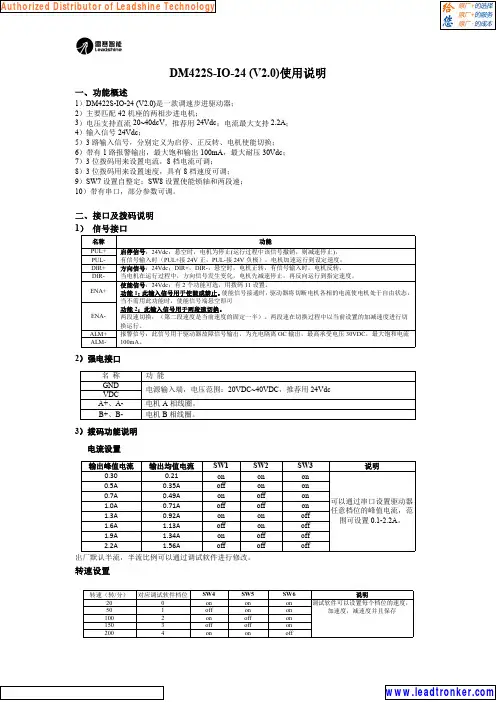
DM422S-IO-24(V2.0)使用说明一、功能概述1)DM422S-IO-24(V2.0)是一款调速步进驱动器;2)主要匹配42机座的两相步进电机;3)电压支持直流20~40dcV ,推荐用24Vdc ;电流最大支持2.2A ;4)输入信号24Vdc ;5)3路输入信号,分别定义为启停、正反转、电机使能切换;6)带有1路报警输出,最大饱和输出100mA ,最大耐压30Vdc ;7)3位拨码用来设置电流,8档电流可调;8)3位拨码用来设置速度,具有8档速度可调;9)SW7设置自整定;SW8设置使能锁轴和两段速;10)带有串口,部分参数可调。
二、接口及拨码说明1)信号接口名称功能PUL+启停信号:24Vdc ;悬空时,电机为停止(运行过程中该信号撤销,则减速停止),有信号输入时(PUL+接24V 正,PUL-接24V 负极),电机加速运行到设定速度;PUL-DIR+方向信号:24Vdc ;DIR+,DIR-:悬空时,电机正转,有信号输入时,电机反转,当电机在运行过程中,方向信号发生变化,电机先减速停止,再反向运行到指定速度。
DIR-ENA+使能信号:24Vdc ;有2个功能可选,用拨码11设置。
功能1:此输入信号用于使能或禁止。
使能信号接通时,驱动器将切断电机各相的电流使电机处于自由状态,当不需用此功能时,使能信号端悬空即可功能2:此输入信号用于两段速切换。
两段速切换,(第二段速度是当前速度的固定一半)。
两段速在切换过程中以当前设置的加减速度进行切换运行。
ENA-ALM+报警信号:此信号用于驱动器故障信号输出,为光电隔离OC 输出,最高承受电压30VDC ,最大饱和电流100mA 。
ALM-2)强电接口名称功能GND 电源输入端,电压范围:20VDC~40VDC ,推荐用24Vdc VDC A+、A-电机A 相线圈。
B+、B-电机B 相线圈。
3)拨码功能说明电流设置输出峰值电流输出均值电流SW1SW2SW3说明0.300.21on on on 可以通过串口设置驱动器任意档位的峰值电流,范围可设置0.1-2.2A 。
1. How the motor controller control the motor speedIn the motor controller, there is a hardware timer T1 that is used to generate stepping pulse for stepper motor or reference position for servomotor. The input clock’s frequency of the timer, plus the preset value of this timer, determine the slewing speed of the motors.When T1 generates an interrupt, it mighto Drive the motor to move 1 step (1 micro-step or 1 encoder tick) for low speed slewing.o Drive the motor to move up to 32 steps for high speed slewing. This method applies to motor controller firmware version 2.xx. For motor controller with firmware 3.xx or above,the motor controller always drive the motor controller 1 steps/interrupt.2. Two motion modeGOTO mode: The master device tells the motor controller the desired destination, and then send a "Start" command. The motor controller will control the motor to move to that destination. The master device can check the motor status, real-time position, cancel the slewing during the GOTO. Speed(Tracking) mode: The master device calculate a proper preset value for T1 and send it to the motor controller, and then send a "Start" command. The motor controller will control the motor to slew at the desired speed. The master device can check the motor status, real-time position, cancel the slewing during the GOTO.There is a command which is used to select between the two motion mode for the next "Start"command. Generally, the motor should be at full stop status before setting the motion mode.Generally, the motor controller returns to "Speed Mode" when the motor stops automatically.A typical slewing session include:o Check whether the motor is in full stop status. If not, stop it.o Set the motion mode.o Set the parameters, for example, destination or preset value of T1.o Set the "Start" command.o For a GOTO slewing, check the motor status to confirm that the motor stops (Generally means arriving the destination. ). For a Speed mode slewing, send "Stop" command to endthe session.3. Calculation on Master DeviceA Skywatcher motor controller does not do complex calculation. The master device do it instead.Calculate the angleA Skywatcher motor controller only counts the step or the ticks of an incremental encoder on themotor shaft. But a master device can inquire the motor controller the resolution of the telescope axis (how many steps the telescope axis have for one revolution). We called it CPR (Counts per revolution). With CPR, the master device can convert an angle to steps or vise versa.Please note that CPR might be different for the two axes of a mount.Calculate the T1 preset value.A Skywatcher MC can report the T1’s input clock frequency TMR_Freq (Mention at the beginningof this article). A master device can use TMR_Freq and CPR to calculate the T1 preset value for desired motor speed.Speed_CountsPerSec = Speed_DegPerSec * CPR / 360T1_Preset = TMR_Freq / Speed_CountsPerSec= TMR_Freq * 360 / Speed_DegPerSec / CPRCalculate the T1 preset value for high speed slewingT1 preset value can be too small for high speed slewing, if T1’s input clock frequency is low. To solve this problem, the motor use a slightly different way to control motor speed when highspeed slewing is required (For example, move an axis with higher then 128x sidereal rate). When T1 generates an interrupt, the motor controller moves N micro-steps for a stepper motor, orchange the reference position for N steps for a DC servo motor. That means, for the same T1preset value, the motor will run N times faster than changing only 1 steps for each T1 interrupt event.Currently, N is a fixed number, and a master device can inquire the motor controller for it. Itmight be 16, 32 or 64.The formula for calculating T1 preset value for high speed slewing is:T1_Preset = N * TMR_Freq * 360 / Speed_DegPerSec / CPRWhen a master wants an axis to slew at high speed, it should let the motor controller know when it configures the motor to the Speed (Tracking) Mode. For GOTO mode, the motor controller will take care of it automatically.4. Command Format:The command always starts with a ":" character and ends with a carriage return character 0x0D.If a second ":" character is received by the motor controller before the carriage return character, then the motor controller will abandon the characters received and starts receiving a newcommand.Motor controller will process the command and send response after it receives the carriage return character.A response from the motor controller always starts with a "=" character and ends with a carriagereturn character, if the response is normal.If there is something wrong, the motor will response a message starts with a "!" character, followed by error code and a carriage return character.All the character in the command and the response are ASCII characters.A command from the master device has the following parts:o1 byte Leading character: ":"o1 byte command word, check command set table for detailso1 byte channel word: "1" for RA/Az axis; "2" for Dec/Alt axis.o1 to 6 bytes of data, depending on command word: character "0" to "9", "A" to "F"o1 byte Ending character: carriage return character.A normal response from the motor controller has the following parts:o1 byte Leading character: "="o1 to 6 bytes of data, depending on which command is processed: "0" to "9", "A" to "F"o1 byte Ending character: carriage return character.An abnormal response from the motor controller has the following parts:o1 byte Leading character: "!"o2 bytes of error code: "0" to "9", "A" to "F"o1 byte Ending character: carriage return character.Data format:o24 bits Data Sample: for HEX number 0x123456, in the data segment of a command orresponse, it is sent/received in this order: "5" "6" "3" "4" "1" "2".o16 bits Data Sample: For HEX number 0x1234, in the data segment of a command or response, it is sent/received in this order: "3" "4" "1" "2".o8 bits Data Sample: For HEX number 0x12, in the data segment of a command or response, it is sent/received in this order: "1" "2".5. Command Set6. HardwareUART: 9600bps, 1 start bit, 1 stop bit, no parity check.Signal level: 5V or 3.3V.On most of the EQ mount, the TX and RX lines are separated. The motor controller will send its response immediately after it received and process the command.On most the Alt/Az mount, TX and RX lines are connected together, and there is another line(Drop) to indicate that the TX/RX bus is busy. The Drop line is controlled by the master only, which means the master device should pull the Drop line to low level when it starts to send acommand and keep pulling it low until it receives the full response from the motor controller, or,a time-out occurs. The motor controller will send its response immediately after it received andprocess the command, thus the master device should release the TX/RX bus as soon as possible after the last bit of the command is shift out of the hardware register.The motor controller pull its TX line to high level with a 5.1K to 10K resistor, other than that, it does not strongly pull the TX line to high level and other devices can pull the TX line to low level without problem.6. Wi-Fi ConnectionThe same protocol runs on the SynScan Wi-Fi dongle or mount with built-in Wi-Fi module.The Wi-Fi dongle/module runs a UDP server and listen to UDP port 11880 to accept commands from host.The command must be sent in a single UDP package; the response is also included in a single package.When the Wi-Fi dongle/module works in access point mount, its IP address is 192.168.4.1. If it runs in station mode, the router that it links to allocates its IP address.6. Useful ResourcesSample Code: https:///archive/p/skywatcher/Documents: /download/manual/application-development/。
--------------------------------------------------------------------- 地址:河北省保定市朝阳南大街511号M430D 步进电机驱动器说明书一. 概述:M430D 为四相步进电机驱动器,驱动电压DC18V-DC40V ,适配电流在3A 以下,适合35,42,57四相混合式步进电机。
细分功能使步进电机转动精度提高,振动减小,杂讯降低。
此款驱动器性价比高,可靠性高,功能完善。
二. 特点:1. 最高输入电压DC40V 。
2. 可插拔式接线端子配线方便。
3. 具有半步、1/4细分、1/8、1/16细分运行方式可供选择。
4. 可调节相电流 输出电流可达3A 。
5. 半电流锁定,停止输入脉冲时电机相电流自动下降,以降低马达温度节省消耗。
6. 具有过热,过压保护功能。
7. 具有正反转控制功能。
8. R/S 启停脱机控制。
三. 驱动器接口介绍:四. 注意:1. 接入电源时注意正负极,切勿接反!!2. LED 灯为电源指示灯,当驱动器通电时此灯亮起。
五. 细分表:1 2 2细分ON ON 4细分ON OFF 8细分OFF ON 16细分 OFF OFF六. 相电流调节:--------------------------------------------------------------------- 地址:河北省保定市朝阳南大街511号2.6A七. 输入信号波形时序图:八. 接线图:保定市宇人科技有限公司技术部 --------------------------------------------------------------------- 地址:河北省保定市莲池南大街513号九. 尺寸图:(单位mm)110*99*46(mm)。
MA860H型两相混合式步进电机驱动器使用说明书概述MA860H型细分型两相混合式步进电机驱动器,采用AC18-80V或DC60V供电,适合驱动电流小于8.0A外径57~86毫米的两相混合式步进电机。
此驱动器采用交流伺服驱动器的电流环进行细分控制,电机的转矩波动小,低速运行平稳,振动和噪音低。
高速时可输出相对较高的力矩,定位精度高。
广泛适用于雕刻机、数控机床、包装机械、传动设备等分辩率要求较高的设备上。
主要特点1 平均电流控制,两相正弦电流驱动输出2 AC18-80V或DC60V供电3 光电隔离信号输入/输出4 有过压、欠压、过流、相间短路保护功能5 十四档细分和自动半流功能6 八档输出相电流设置7 具备脱机功能8 启动转速高9 高速力矩大电气参数DC60输入电压 V供电输入电流 小于8安培输出电流 2.0A~7.8A温 度 工作温度-10~45℃;存放温度-40℃~70℃湿 度 不能结露,不能有水珠气 体 禁止有可燃气体和导电灰尘重 量 450克注:拨码开关请在未上电时调好,严禁带电操作,切记!控制信号接口图1是驱动器的接线原理图1、控制信号定义PUL+: 步进脉冲信号输入正端PUL-: 步进脉冲信号输入负端DIR+: 步进方向信号输入正端DIR-: 步进方向信号输入负端ENA+: 脱机使能复位信号输入正端ENA-: 脱机使能复位信号输入负端脱机使能信号有效时复位驱动器故障,禁止任何有效的脉冲,驱动器的输出功率元件被关闭,电机无保持扭矩。
2、控制信号连接上位机的控制信号可以高电平有效,也可以低电平有效。
当高有效时,把所有控制信号的负端连在一起作为信号地,低有效时,把所有控制信号的正端连在一起作为信号公共端。
现在以集电极开路和PNP输出为例,接口电路示意图如下:图2. 输入接口电路(共阴极接法)控制器PNP输出注意:VCC值为5V时,R短接;VCC值为12V时,R为1K,大于1/8W电阻;VCC值为24V时,R为2K,大于1/8W电阻;R必须接在控制器信号端。
3M583(三相高性价比)细分步进驱动器使用手册Version1.0版权所有不得翻印【使用前请仔细阅读本手册,以免损坏驱动器】宁波纳川自动化科技有限公司3M583步进电机驱动器使用说明在使用本品前,请仔细阅读本使用说明书请妥善保管本说明书,以备日后参考本册外观图片仅供参考,请以实物为准安全注意事项请勿带电插拔连接线缆。
此产品非密封,请勿在内部混入镙丝、金属屑等导电性异物或可燃性异物,储存和使用时请注意防潮防湿。
驱动器为功率设备,尽量保持工作环境的散热通风。
在连上步进电机,调节好电流后使其连续工作半小时后观察步进电机是否在额定温度后方可进行后续使用,如果电机温度过高请联系制造商。
一、产品简介1.1 产品概述3M583是纳川科技最新推出的一款采用精密电流控制技术设计的高细分步进电机驱动器,适合驱动57-86型各种品牌的三相混合式步进电机。
由于采用了先进的抗噪声控制方法,能大幅度降低电机运转时的噪声和振动,使得步进电机运转时的噪声和平稳性趋近于伺服电机的水平。
和市场上的大多数其他细分驱动产品相比,步进电机和驱动器的发热量降幅达15-30%。
1.2 产品特点■高性价比、超低噪声■电机和驱动器发热均较低■供电电压可达50VDC■输出电流峰值可达8.3A (均值5.9A)■输入信号TTL兼容,静止时电流自动减半■可驱动3、6线三相步进电机■光隔离差分信号输入■脉冲响应频率最高可达400KHz(更高可选)■多达8种细分可选1.3 应用领域适合各种中小型型自动化设备和仪器,例如:雕刻机、打标机、切割机、激光照排、绘图仪、数控机床、拿放装置等。
在用户期望低成本、小噪声、高速度的设备中效果特佳。
二、电气、机械和环境指标2.1 电气指标说明3M583最小值典型值最大值单位输出电流 2.09(均值1.48)- 8.3(均值5.8) A 输入电源电压18 36 50(含纹波)VDC 逻辑输入电流7 10 16 mA 步进脉冲频率0 - 400 KHZ 绝缘电阻500 MΩ2.2 使用环境及参数冷却方式自然冷却使用环境场合尽量避免粉尘、油雾及腐蚀性气体环境温度0℃-+50℃最高工作温度70℃湿度40-90% RH9 (不能结露和有水珠)震动 5.9m/S2 Max保存温度-20℃-125℃重量约300克2.3 机械安装图 单位:毫米2.4 加强散热方式(1)驱动器的可靠工作温度通常在65℃以内,电机的工作温度在80℃以内;(2)安装驱动器时请采用竖着侧面安装,形成较强的空气对流,必要时机内靠近驱动器出安装风扇,强制散热,保证驱动器在可靠的工作温度范围内工作。
L297 L298步进电机驱动控制板说明书
一、板子跳线器说明:
1、靠近光偶的短路冒打在CLK-555方向时有板上的555提供时钟给驱动器;打在CLK-CP U时右用户CPU提供时钟给驱动器。
2、JT5打在右边:297的HALF/FULL(全速/半速)脚接GND了默认为FULL模式了;JT5打在左边:297的HALF/FULL脚空了电机模式用户自己控制。
3、JT6打在右边:297的CW/CCW脚(方向)接GND了默认为顺时针转动模式了;JT6打在左边:297的CW/CCW脚空了电机正反转模式用户自己控制。
二、按键说明:
板子使用全新的L297作为控制芯片 L298作为驱动芯片板载NE555时钟电路为L297提供CLK因此该版在不需要外部控制的情况下就可以工作板载3个控制按键EN - 使能
CW - 反向旋转
HF - 半速旋转
通过按键就可以直接控制电机的正反转、全速/半速和使能。
三、基本功能描述:
通过光藕隔离之后将CLK CW HF EN四个基本控制端引出单片机等可以非常方便的控制电路的工作这个板子改进的地方比较多也方便研究使用。
板子使用1N5822快速二极管作为续流器件其速度要远远快于整流桥的 L298和电机能够提供更完善的有效的保护。
模块供电+ 5V(L297和L298控制供电) +12V(根据电机最低4V最高16V)给电机供电。
电机输出接口包括: +12V 四相输出 GND(请根据您的电机连接)。
控制输入接口包括: GND CLK EN CW HF。
需要特别说明的是:为了测试方便在板子上设置了NE555构成的一个低频时钟源(使用时跳线冒打在CLK-555处),当您使用外部的时钟信号控制电机的转速时必须跳线冒打在CLK -CPU处否则外部时钟是不会传到L297里面。
四、接口说明:
1、板子左上方小二接口(JT1) VCC接+5V、GND接电源地,次处为芯片L297和555芯片的工作电压;
2、板子左中方小八接口(MCU-IN)为光藕隔离的信号分别为:EN(使能)、RET(复位)、C/CW(正反控制)、H/FU(全速/半速)、CLK(时钟信号) +5V(光藕工作电压)注意:如果没有用C PU控制,小八接口(MCU-IN)的信号可以不接任何东西。
3、JT2为298的工作电压也是驱动电机的工作电压(接+12V)
注意:板子推荐的最高电机供电电压在4V~18V之间最大工作电流不超过2A 否则L298的耗散功率会过大导致发热严重这种情况下通过风冷等措施可以提高最大工作电流到2. 5A左右。
4、OUT为电机的四相信号线 A B C D。