THK交叉导轨
- 格式:pdf
- 大小:265.46 KB
- 文档页数:8
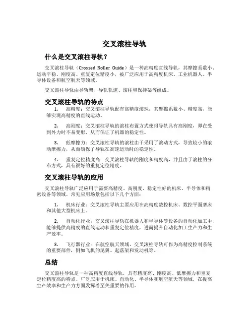
交叉滚柱导轨什么是交叉滚柱导轨?交叉滚柱导轨(Crossed Roller Guide)是一种高精度直线导轨,其摩擦系数小、运动平稳、刚度高、重复定位精度小,被广泛应用于高精度机床、工业机器人、半导体设备和航空航天等领域。
交叉滚柱导轨由导轨架、导轨轨道、滚柱和保持架等组成。
交叉滚柱导轨的特点1.高精度:交叉滚柱导轨配有高精度滚珠,其摩擦系数小、精度高,能够实现高精度的直线运动。
2.高刚度:交叉滚柱导轨的滚柱布置方式使得导轨具有高刚度,即在受到外力时不易变形,从而保证了机器的稳定性。
3.低摩擦力:交叉滚柱导轨的滚柱由于采用了滚动方式,导致较小的滚动摩擦力,从而确保了导轨在高速运动时的稳定性。
4.重复定位精度高:交叉滚柱导轨的刚度和精度高,并且由于滚柱的分布方式,具有很好的重复定位精度。
交叉滚柱导轨的应用交叉滚柱导轨广泛应用于需要高精度、高刚度、稳定性好的机床、半导体和精密设备等领域。
常见应用场景包括以下几个方面:1.机床行业:交叉滚柱导轨主要应用在高精度数控机床、数控平面磨床和其他大型机床上。
2.自动化行业:交叉滚柱导轨在机器人和半导体等设备的自动化加工中,能够提供高精度的直线运动和重复定位精度,进而提升自动化加工生产力和生产效率。
3.飞行器行业:在航空航天领域,交叉滚柱导轨可作为高精度控制系统的重要部件,例如飞机的尾翼、起落架和发动机等。
总结交叉滚柱导轨是一种高精度直线导轨,具有精度高、刚度高、低摩擦力和重复定位精度高的特点。
广泛应用于机床、自动化、半导体和航空航天等领域,在提高生产效率和生产力方面发挥着至关重要的作用。
THK介绍THK轴承THK轴承公司介绍日本THK公司于1971 年,在日本东京Meguro-ku 成立,最初名称为 Toho Seiko Co., Ltd.。
后更名THK C O.,LTD。
“THK”代表“ Toughness(坚韧)”、“ High Quality(高品质)”和“ Know-how(技术诀窍)”。
THK发展历程:1971 年,THK 在东京 Meguro-ku 成立,最初名称为 Toho Seiko Co., Ltd.。
1972 年,THK 成为世界上第一家开发通过滚动接触实现直线运动的方法的公司,并开始制造和销售商业化的成果:直线运动 (LM) 导轨。
1977 年,THK 的 Kofu 工厂(第一家完善的 LM滚动导轨生产厂)成立。
这是 THK 扩大生产设施的第一步。
1981 年在美国成立了 THK America Inc.,次年在德国成立了 THK Europe,为国际销售网络的扩展打下了基础。
1984 年在日本成立了 Gifu 工厂,并于 1985 年在日本成立了 Mie 工厂和 Yamaguchi 工厂,进一步扩大生产能力。
1996 年,THK 开发了“球保持器型 LM滚动导轨”,这种产品的性能显著优于传 THK直线轴承统产品。
如今THK拥有四位一体的生产和销售基地:日本、欧洲、美洲和亚洲。
THK产品及应用:THK公司的“直线运动系统”飞跃性地提高了工作机械、产业用自动装置、半导体制造装置等先进机电一体化设备的高精度化,省力化,高速化等机械性能,并为其商品化做出了划时代的贡献。
THK凭借独特的机械组件,包括LM 导轨设备,滚珠花键、滚珠丝杠和连杆球,享誉全球。
THK直线运动系列产品广泛应用于机床、加工中心、汽车、橡胶、包装、工业机器人、半导体制造装置、医疗器械及其他各种电子控制机器等。
LM导轨的先驱机器的运动零件可分为滚动件、直线运动件或两者的组合件。
随着大约 110 年前滚动轴承的开发,滚动接触成为了实现滚动运动的标准方法。
交叉导轨材料和表面处理工艺交叉导轨材料和表面处理工艺一、交叉导轨材料的选择•金属材料•不锈钢•铝合金•非金属材料•聚合物•复合材料二、交叉导轨材料的性能要求•机械性能•强度•刚度•耐磨性能•腐蚀性能•导电性能三、交叉导轨材料的表面处理工艺•防腐处理•清洗•酸洗•磷化•表面涂层•清洁涂层•防腐涂层•润滑涂层四、交叉导轨材料和表面处理工艺的重要性•提高导轨使用寿命•降低维护成本•提高导轨运行的可靠性和安全性五、结论交叉导轨材料的选择和表面处理工艺的使用对于提高导轨的性能至关重要。
通过选择合适的材料和优化的表面处理工艺,可以大大延长导轨的使用寿命,降低维护成本,并提高导轨运行的可靠性和安全性。
六、金属材料的选择金属材料是交叉导轨常见的选择,主要有不锈钢和铝合金两种。
1. 不锈钢不锈钢具有良好的抗腐蚀性和耐磨性,适合在恶劣的环境中使用。
同时,不锈钢强度高、刚度好,可以承受较大的载荷。
2. 铝合金铝合金具有较轻的重量,比不锈钢更适合在需要降低重量的场景中使用。
此外,铝合金具有良好的导热性和导电性,可以有效地散热和传输电流。
七、非金属材料的选择除了金属材料外,交叉导轨也可以使用非金属材料,主要有聚合物和复合材料两种。
1. 聚合物聚合物材料通常具有较好的耐磨性、耐腐蚀性和电绝缘性能。
此外,聚合物材料相对较轻,便于安装和维护。
不过,聚合物材料的强度和刚度相对较低,需要在设计时进行合理的加强结构。
2. 复合材料复合材料的优点是结合了不同材料的优势,具有较高的强度和刚度,同时具备良好的耐磨性和耐腐蚀性。
复合材料还可以根据需要进行定制,满足不同应用场景的需求。
八、交叉导轨材料的性能要求在选择交叉导轨材料时,需要考虑以下性能要求:1. 机械性能交叉导轨需要具备足够的强度和刚度,以支撑和承载物体的运动。
材料的强度和刚度要根据实际情况进行选取,以确保导轨能够承受预期的应力和负荷。
2. 耐磨性能交叉导轨在使用过程中,经常会受到磨擦的作用,因此需要具备良好的耐磨性能,以确保导轨的使用寿命。

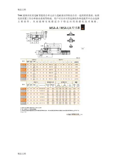
THK滚珠丝杠的LM智能组合单元由与LM滚动导轨结合在一起的铝质基座、标准化的顶置工作台和驱动系统等构成。
用户可以从可供选择的各种选配件中自由选择主要部件,从而能够实现最适合于特定应用的最优技术规格。
THK滚珠丝杠滚珠花键是一种滚动导轨花键。
这是一款创新型产品,通过滚珠在与轴相连的槽道中的滚动,可实现比使用直线轴套时更大的容许负荷,且可以在进行直线运动的同时传递扭矩。
由于花键轴表面采用镜面加工,因此THK滚珠丝杠可获得平滑的滑动。
另外,接触面积较大,并具有在施加扭矩时自动定心的同心性,因此传递扭矩时可发挥稳定的性能THK 标准导程精密滚珠螺杆结构与特长在循环导管式螺母的滚珠螺杆中,承受轴方向负荷的负荷滚珠在螺杆轴和螺母上所开设的滚动沟槽上顺着轴的周围滚动后,进入埋在螺母内部的循环导管中成为无负荷,通过导管再返回负荷领域,如此进行滚动运动的无限循环。
这种型式的滚珠螺杆是系列中种类最丰富,最普及的型式,被广泛地使用于各种各样的用途。
丰富的轴径与导程的组合您可以从各种螺母类型和丝杠轴导程的组合中,选择符合使用条件的轴径和导程的组合,螺母类型包括回流管螺母,紧凑型单螺母和大导程端盖螺母轴端末加工的丝杠轴类型,其丝杠轴按标准长度来进行批量制造;轴端完成加工的丝杠轴类型,在其中丝杠轴经过加工以配合相应的支撑单元,这2类型均作为标准件提供。
备有满足使用环境要求的任选构件提供的任选购件包含QZ自润滑润滑器和清洁环(w),前者使维修的时间显着延长,而后者提高了在恶劣环境中排除异物的能力。
THK 带球保持器的高速滚珠螺杆为了消除钢珠之间的碰撞和相互摩擦﹐并提高保持润滑剂的性能﹐在钢珠之间安装了球保持器。
由此实现了低噪音和优异的扭距性能﹐并可长期免维修保养。
采用透过回流管使钢珠按切线方向上行的理想的循环结构﹐提高了循环部分的强度﹐达到了DN值13万的容许值。
(: DN值=钢珠中心直径X每分钟的转速)预压方式采用了在一个螺母的正中间﹑使两侧螺纹的导程相对移动的偏置预负荷方式。
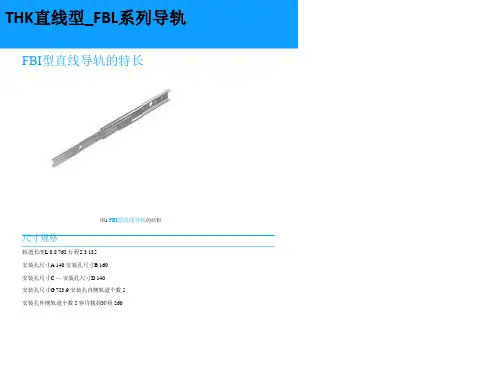
[精品]THK直线导轨分类工程导读:金属或其它材料制成的槽或脊,可承受、固定、引导移动装置或设备并减少其摩擦的一种装置,直线导轨又称滑轨、线性导轨、线性滑轨,用于直线往复运动场合,拥有比直线轴承更高的额定负载,同时可以承当一定的扭矩,可在高负载的情况下实现高精度的直线运动高效耐用,以THK直线导轨为例:一.THK直线导轨采用球保持器,可消除滚珠的相互摩擦,实现低噪音、好音质、长期免维护和优异的高速性。
1.世界标准-THK直线导轨SHS型各球列按45°接触角配置,因此可在任何姿势下使用。
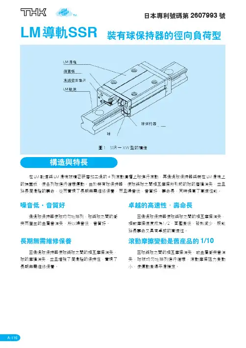
2.THK径向型-THK直线导轨SSR型断面高度较低的紧凑型,采用相对径向方向呈90°的球接触结构,最适合于水平引导部。
3.THK超重负荷(径向型)-THK直线导轨SNR型球保持器型LM导轨系列中刚性最高的径向型LM导轨。
4.THK超重负荷(4方向型)-THK直线导轨SNS型球保持器型LM导轨系列中刚性最高的4方向型LM导轨。
5.THK宽幅轨道型-THK直线导轨SHW型 LM轨道采用宽度很大的低重心结构,具有优异的Mc扭矩的4方向等负荷型LM导轨。
6.THK微型-THK直线导轨SRS型 LM轨道断面高度较低、实现了轻量、紧凑结构的LM导轨。
7.THK双维一体式LM滚动导轨-THK直线导轨SCR型采用直交的直动系统,实现了无鞍部的紧凑的X-Y运动的LM导轨。
二.保持器型滚柱滚动导轨采用滚子保持器,实现了低磨擦、平滑运动、长期免维护的超超高刚性滚子导轨1.THK超高刚性型-THK直线导轨SRG型与本公司总球LM导轨相比刚性达2倍的超超重负荷滚子导轨。
采用全球标准尺寸,实现了长期免维护。
2.THK超高刚性型(低重心型)-THK直线导轨SRN型与机床用LM导轨SNR型兼容3. 采用大宽度的滚子导轨,提高了安装强度、安装稳定性。
三.HK直线导轨(全钢球型) 从小型到机床用的大型,从直线引导到曲线引导,适合各种用途的型号系列化。
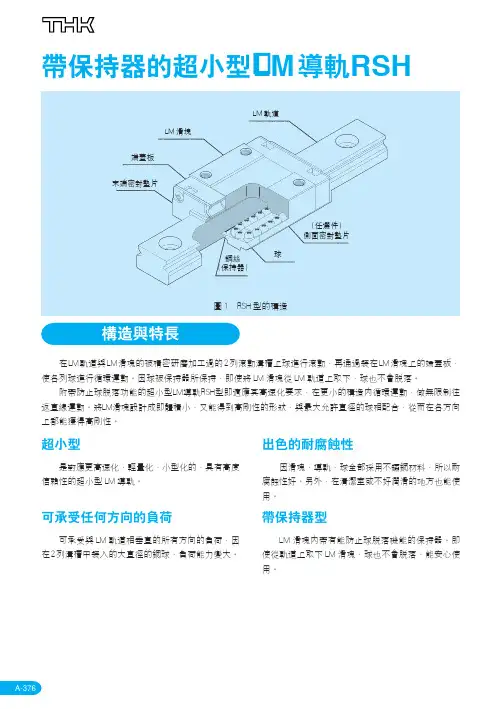
A-284InterchangeabilityThe LM rail and block of this type are interchangeable with one another. As a result, rails and blocks can be stored separately. It is even possible to cut a long LM rail to a desired length and couple it with any LM block.CompactType GSR is designed to be as low-profile as possible.This enables it to provide stable linear motion and keep the center of gravity low, making it possible to construct compact machine systems.Bears loads in all directionsThe ball-contact angle is designed to bear loads in all directions. Type GSR is therefore applicable where moments can act in any direction, including reverse-radial and lateral.Japanese patent Nos.: 1388133, 1405187, and 1613980Overseas patents registered in the U.S., Germany, U.K., France, Italy, and South KoreaLM Guide GSR - Interchangeable self-adjusting typeFig. 1 Construction of Model GSRLM blockEnd plateEnd sealLM railRetainer plateBallSide sealCross sectionBalls roll in two rows of precision-ground raceway on an LM rail and an LM block. The end plate attached to the LM block causes the trains of balls to circulate. As the balls are held in place by the retainer plate, they do not fall off if the LM block is removed from the rail.As the LM-block top surface is tilted, by simply fastening the mounting bolts, clearances can be eliminated and an appropriate preload can be applied.As type GSR has a special contact design employing a circular-arc groove, even if levelness and rail parallelism are not fully established, it can provide smooth linear motion with no affect on service life. With its high self-adjusting capability, type GSR is best suited for uses in which high installation accuracy is difficult to achieve, and in industrial machines in general.With large-diameter balls arranged in two rows of circular-arc grooves. Features an excellent self-adjusting capability, enabling it to compensate for mounting-surface errors, thereby ensuring smooth linear motion.Type GSR-T modified by shortening the LM block; therefore space-savingA-285Type GSR can bear loads in all four directions: radial,reverse-radial, and the two lateral directions.The basic load rating is for a load in the radial direction on one LM block in the diagram shown above. The values are given in the corresponding dimension tables. Values for the reverse-radial, tensile, and compressive lateral directions are given in Table 1.Equivalent loadThe equivalent load for type GSR when loads in the radial, tensile lateral, reverse-radial, and compressive lateral directions are exerted on its LM block simultaneously can be obtained using the following equation:P E = X •P R + Y •P Tt P E = P L + P TC whereP E : equivalent load (N)- In the radial direction- In the reverse-radial direction - In the tensile lateral direction- In the compressive lateral directionP R : radial load (N)P L :reverse-radial load (N)P Tt :tensile lateral load (N)P TC : compressive lateral load (N)X and Y : equivalent factorA-286Load ratingFig. 2C LC 0L C T tC 0T tC C 0C T cC 0T cRadial direction Reverse-radial direction TensionCompression Table 1 Type-GSR Load Ratingsin Various DirectionsTable 2 Type-GSR Equivalent Factor (under radial and tensile lateral loads)In type GSR, a single LM block can bear moments in directions M A and M B . The moment in direction M C can be applied if the LM Guide system uses two LM rails in parallel. Table 3 gives the permissible moments in directions M A and M B for a single LM block. The data on permissible moments in direction M C is omitted here, as the moment depends on the distance between two rails.A-287A-IVFig. 3Table 3 Type-GSR Static Permissible MomentM AM BA-288The accuracy of type GSR is shown in Table 2 for eachmodel number, classified into the normal, high, and precision grades.Fig 4MTable 4 Type GSR Accuracy Standard³D , ³C (µm )40302010010002000300040005000H PFig. 5 Relationship Between LM-Rail Length and Running ParallelismNormal grade Rail length (mm)A-IVA-289Seal resistanceThe maximum values for seal resistance per LM block in type GSR...UU with a lubricant applied are given in Table 6.A-290From our wide array of products for type GSR, you can select the one best suited for your situation. (For details on seals, see “Contamination Protection” for type HSR on page A-223.)If your choice is applicable to your system, please note that in some models, attaching a contamination-protection accessory to an LM block changes the block’s overall length. Add the increment specified in the correspondingdimension table to dimension L.Table 5 Applicability of Seals to Type GSR, and the Increment to Be Addedto the Block Overall LengthUnit : mmNote: Ο= ApplicableTable 6 Maximum Resistance Valueof seals to Type GSRLM Guide type GSR can be mounted by the procedure specified below.1.H old the table against the LM-block referencesurface. Fully fasten bolts. The table must have a reference section on both sides.2.Position LM rail A on the base along a straight edge.Using a torque wrench, fully fasten the rail.3.Temporarily fasten LM rail B to the base. Insert ablock into the rail.With pressing LM rail B against the block, temporarily fasten the bolts.4.Move the table a couple of strokes. Break in the LMblock on the rails. Using a torque wrench, fully fasten LM rail B.If multiple sets are to be mounted, prepare a jig as shown. The jig facilitates the establishment of parallelism between LM rails.A-291Fig. 6 Fig. 7Fig. 8 Fig. 9 Fig. 10TableReference section Reference sectionStraight edge Base Rail ATablePress this wayRail ARail BRail ARail BTorquewrenchLM railBaseMounting jigBaseA-292Preloadadjustment boltTo increase rigidity, a reference section can be installed on the outer side of each LM block.By pressing the blocks sideways with set screws, a preload is exerted on the guideway, thereby increasing rigidity.Fig. 11 Sample Preload Adjustment Using Set ScrewsMounting-Surface Height and Corner ProfileNormally, mounting surfaces for LM blocks and rails have lateral reference surfaces to aid in positioning rails and blocks with a high degree of accuracy.For the reference-surface shoulder height, see Table 7.Furthermore, provide enough space to the corner profile of a mounting surface so that the corner does not interfere with chamfers made on the LM blocks or rails, or provide the corner with a radius smaller than corner radius r specified in Table 7.Fig. 12Table 7 Mounting-Surface Shoulder Height and Corner RadiusUnit : mmTable 8 gives the standard and maximum LM-rail lengths for type GSR.If many rails of different lengths are used, it iseconomical to stock LM rails of the maximum length,as they can be cut to the desired lengths in accordance with the necessary number of strokes.A-293G FGLUnit : mmTable 8 Type-GSR LM-Rail Standard and Maximum LengthsTapped-hole LM rail type GSR-K•The LM-rail bottom surface is provided with tapped holes, whereby H -shapes, channels, and similar steel materials can easily be attached.•Because there are no mounting holes on the LM-rail surface, no foreign matter (e.g., cutting chips) can enter the system, resulting in improved sealability.1.Set a bolt length that will ensure a clearance of 2 to 3mm at the tip of each bolt when the bolt is tightened over the full length of the effective tapped thread.2.We can also provide tapered washers that can be attached to steel shapes as shown in Fig. 13.3.For the model-number coding, see page A-289.Table 9 Tapped-Hole Position and DepthFig. 13M 1✲B 2W 1STapered washersA-294Type GSR-T (long type)Type GSR-V (short type)Notes:•For model-number coding, see page A-289.•For permissible static moments M A and M B , see page A-287.A-295•For standard LM-rail lengths, see page A-293.Unit : mmN-S x lW B N N K d (E)(E)Fd B W M W K 1MhReduces working and assembly costsThe one-piece structure integrating the LM rail (linear guide) and rack (drive) reduces the man-hours required to work the mounting surface for receiving a rack, and to attach it to the rail. This substantially reduces overall costs.Facilitates designThe displacement per turn of the pinion is in increments of integral multiples. This makes it easy to calculate the displacement per pulse when the LM Guide is used in combination with a stepping or servo motor.Space-savingThe rack and the LM rail are formed into one unit. As a result, a system using this type of LM Guide can be made compact in size.Free strokeThe LM-rail end faces are finished for connected use.To obtain a rail for use with long strokes, simply connect LM rails of the standard length.High durabilityThe rack-tooth width is equal to the LM-rail height.The material is high-grade steel with proven high performance, and the rack teeth are heat-treated,thereby ensuring the high durability of type GSR-R.A-296Rack-toothed LM Guide Type GSR-RFig. 1 Construction of type GSR-RSpur rack-toothedtype GSR-RBalls roll in two rows of precision-ground raceway on an LM rail and an LM block. The end plate attached to the LM block causes the trains of balls to circulate. As the balls are held in place by the retainer plate, they do not fall off if the LM block is removed from the rail.As the LM-block top surface is tilted, by simply fastening the mounting bolts, clearances can be eliminated and an appropriate preload can be applied.Type GSR-R is a modification of type GRS, with the rack teeth cut on the LM rail. This aids in the design and assembly of drive mechanisms.A-IV■Can be used if the pinion mounting part doesnot have high rigidityAs the thrust load on the pinion shaft can be kept lowdue to rack-pinion meshing, it is easy to designsystems with pinion shaft bearings and tables that arenot high in rigidity.Load Rating and Permissible Moment in Various DirectionsLoad ratingFig. 2C LC0LC TtC0TtCC0C T cC0T cRadialdirectionReverse-radialdirectionTensionCompressionType GSR-R can bear loads in all four directions: radial,reverse-radial, and the two lateral directions.The basic load rating is for a load in the radial directionon one LM block in the diagram shown above. Thevalues are given in the corresponding dimensiontables. Values for the reverse-radial, tensile, andcompressive lateral directions are given in Table 1.A-297A-298Equivalent loadThe equivalent load for type GSR-R when loads in the radial, tensile lateral, reverse-radial, and compressive lateral directions are exerted on its LM block simultaneously can be obtained using the following equation:P E = X •P R + Y •P Tt P E = P L + P TC whereP E : equivalent load (N)- In the radial direction- In the reverse-radial direction - In the tensile lateral direction- In the compressive lateral directionP R : radial load (N)P L :reverse-radial load (N)P Tt :tensile lateral load (N)P TC : compressive lateral load (N)X and Y :equivalent factorM AM BFig. 3A-299The accuracy of type GSR-R is shown in Table 4 foreach model number, classified into the normal and high grades.Fig. 4M³D ,³C (µm )40302010010002000300040005000HFig. 5 Relationship Between LM-Rail Length and Running ParallelismNormal grade Rail length (mm)* If LM rails of various lengths are to be put to butt jointed use, contact us.Note: One model number in this example isrequired for one LM Guide in a one-axis configuration.Separate-part model number●LM block model number ●Rack-toothed-LM-rail model number A-300One-Axis LM GuideReeworking the pinion holeOnly the teeth of the pinion-hole-diameter reworkingtype (type C) are heat-treated. The hole and keywaycan therefore be reworked by the user to the desireddiameter and shape.When carrying out reworking, be sure to take thefollowing into consideration.Material of the hole-diameter reworking type (type C):S45C1.When chucking the teeth of a hole-diameterreworking-type pinion, use a jaw scroll chuck orsimilar tool so as to maintain the tooth profile.2.The pinion is produced using the hole center as areference point. The hole center should thereforebe used as a reference point when the pinion isaligned. When checking the pinion run-out, refer tothe boss sides.3.Keep the reworked hole diameter within 60% to 70%of the boss diameter.Lubricating the rack and pinionTo ensure smooth sliding on tooth surfaces andprevent wear, the teeth should be provided with alubricant.* Use a lubricant of the same type as that sealed in theLM Guide.A-301Mounting-Surface Height and CornerProfileSee Table 7, as the reference section is placed on theopposite side of the rail compared to its position in thestandard type GSR.Fig. 6Fig. 7 Rack Alignment MethodRack-aligning jigJoint between rack teethThe end faces of rack-toothed LM rails are finished soas to ensure a clearance that will aid in theirconnection.Use of the special jig shown in Fig. 7 will makeconnection even easier. (We also offer a special jig foraligning rack teeth.)Fig. 8Scroll chuckFEHChecking strengthThe strength of the assembled rack and pinion must be checked in advance.1.Calculate the maximum thrust exerted on the pinion.2.Divide the permissible power-transmission capacity of the pinion to be used (Table 8) by an overload factor (Table 9).3.By comparing the thrust exerted on the pinion obtained in step 1 with the pinion power-transmission capacity obtained in step 2, make sure the loaded thrust is not greater than the permissible power-transmission capacity.[Calculation example]Type GSR-R is used in a horizontal conveyance system subjected to medium impact (assume external loads to be zero).ConditionsSubject model No. (pinion)GP6-20A Mass (table + work)m = 100 kg Velocityv = 1 m/s Acceleration/deceleration timeT 1= 0.1 sConsideration1.Obtain the maximum thrustCalculate the thrust during acceleration and2.power-transmission capacity3.In this way, the applicability of the subject modelnumber can be judged.A-302Fmax < PmaxPinion●Pinion for racks (type A)Keyway working typeA-3031) When placing an order, specify the model numbers given in this table.2) We can provide non-standard pinions with a different number of teeth. If you require them, contact us.1) When placing an order, specify the model numbers given in this table.2)We can provide non-standard pinions with a different number of teeth. If you require them, contact us.J KKeywayøAP C DBF EH3–GøD H 7øCøAP C DBF EøD H 7øC●Pinion for racks (type C)Hole-diameter reworking typeLM-Rail Standard and Maximum Lengths The LM-rail standard lengths of rack-toothed LM Guide type GSR-R are shown in Table 10As LM rails of type GSR-R are provided with a special end-face finish, they can be connected without further working.A-304Sample table assemblyA-305A-IVClearanceadjustment screw (pinion)PulleyLM blockRack-toothed LM rail Pinion MotorMotorBeltPulleyClearanceadjustment screw (Pinion, LM Guide)LM blockPinionRack-toothed LM rail (GSR-N Type)A-306Rack-Toothed LM Guide Type GSR-RNotes:•LM Guides with special modules and pitches can be manufactured. Please contact THK for further information.•For model-number coding, see page A-300.•For the procedure for checking pinion strength, see page A-302.A-IVW1T1M1NB1BT2KM1MB2EW2W3WPFCL1LL1L4-Sx✲2-Sx✲d drill throughøD counter bore depth h•For LM-rail standard lengths, see page A-304.•For static permissible moments MAand MB, see page A-298.(10)(10)A-307A-308。