第20讲-biosensor
- 格式:pdf
- 大小:1.30 MB
- 文档页数:59

博思廷标准化版本安装和使用手册目录1.安装1.1 boostiv-server(ivas-分析、vsms-分发、vrms-存储、ams-告警)1.1.1选择boostiv-server.msi双击打开安装界面。
1.1.2进入安装界面,然后点击下一步。
1.1.3选择默认安装路径,或点击更改,选择其它安装路径;然后点击下一步。
1.1.4点击安装,开始安装ivas、vsms、vrms、ams服务。
1.1.5安装成功,点击完成。
1.1.6安装完成后,桌面显示BSTAIRSConfig(其它4个服务的配置界面)、ivas、vsms、vrms、ams图标。
1.2 ivms平台1.2.1选择ivms.msi双击打开安装界面。
1.2.2进入安装界面,然后点击下一步。
1.2.3选择默认安装路径,或点击更改,选择其它安装路径;然后点击下一步。
1.2.4点击安装,开始安装ivms平台。
1.2.5安装成功,点击完成。
1.2.6安装完成后,桌面显示BSTivms-平台、cmc-平台配置、BSTMplayer-播放器,图标。
1.3其它辅助软件vc++2005、vc++2008、mysql-5.1.67、加密狗驱动1.3.1点击插件exe文件,全部保持默认完成安装。
1.3.2 MySql安装,选择mysql-5.1.67-win32.msi双击打开安装界面。
保持默认选项,直到出现如下界面,勾选Include Bin Directory in Windows PATH,点击NEXT:密码必须为admin不可更改,勾选Enable root access from remote machines,点击NEXT,继续保持默认选项,完成安装:2.服务配置2.1 boostiv-server服务配置(BSTAIRSConfig、ivas、vsms、vrms、ams)2.1.1双击BSTAIRSConfig图标,打开配置界面。
2.1.2 ivas配置。
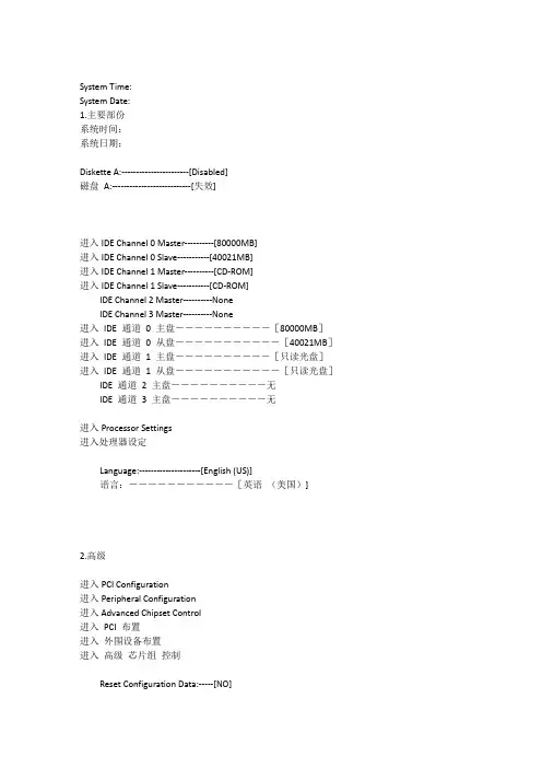
System Time:System Date:1.主要部份系统时间:系统日期:Diskette A:-----------------------[Disabled]磁盘A:---------------------------[失效]进入IDE Channel 0 Master----------[80000MB]进入IDE Channel 0 Slave-----------[40021MB]进入IDE Channel 1 Master----------[CD-ROM]进入IDE Channel 1 Slave-----------[CD-ROM]IDE Channel 2 Master----------NoneIDE Channel 3 Master----------None进入IDE 通道0 主盘----------[80000MB]进入IDE 通道0 从盘-----------[40021MB]进入IDE 通道 1 主盘----------[只读光盘]进入IDE 通道 1 从盘-----------[只读光盘]IDE 通道2 主盘----------无IDE 通道3 主盘----------无进入Processor Settings进入处理器设定Language:---------------------[English (US)]语言:-----------[英语(美国)]2.高级进入PCI Configuration进入Peripheral Configuration进入Advanced Chipset Control进入PCI 布置进入外围设备布置进入高级芯片组控制Reset Configuration Data:-----[NO]Numlock:----------------------[On]Boot-time Diagnostic Screen:--[Enabled]ACPI Suspend Type:------------[S3]复位布置数据:-----[不]数字锁:-----------[开]引导时间诊断荧屏:--[激活]ACPI 中止类型:------------[S3]Set User Password ----------------[Enter]Set Supervisor Password-----------[Enter]固定的使用者密码----------------[进入]固定的管理者密码-----------[进入]Fixed disk boot sector:----------[Normal]硬盘引导扇区-------[常态]Power Switch:---------------------[Enabled]电源开关:---------------------[激活]Floppy Write Protect--------------[Normal]软盘写入保护-------[常态]Chassis Intrusion-----------------[Disabled]底盘干扰-------------[失效]Reset Chassis Intrusion-----------[Press Enter]重新设定底盘干扰---------[按Enter键]4.服务进入System ManagementAC-LINK:-------------------------[Stay Off]Temperature Sensor----------------[Enabled]Upper Limit:--------------------[60]Lower Limit:--------------------[ 5]POST Error Pause------------------[Enabled]进入系统管理AC-联接:-------------[保持关]温度感应器----------------[激活]上限:--------------------[60]下限:--------------------[5]通电自检程序错误暂停------------[激活]5.Removable DevicesCD-ROM Drive+Hard DriveIBA GE Slot 0208 v1215可移动的装置只读光盘驱动器+硬盘IBA GE 位置0208 v 1215& Exit。
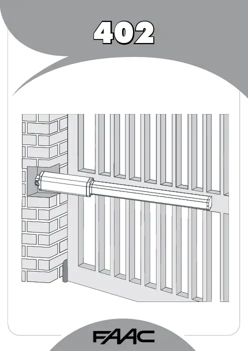
1FAAC S.p.A.Via Benini, 140069 Zola Predosa (BO) - ITALIATel.: 051/61724 - Fax: 051/758518www.faac.it732143 Rev.A.EC DECLARATION OF CONFORMITY FOR MACHINES ....................................................................................p. 2 WARNINGS FOR THE INSTALLER .......................................................................................................................p. 2 1.DESCRIPTION AND TECHNICAL SPECIFICATIONS ....................................................................................p. 31.1.DIMENSIONS ................................................................................................................................p. 32.ELECTRIC DEVICES (standard system) ....................................................................................................p. 33.INSTALLING THE AUTOMATED SYSTEM ......................................................................................................p. 43.1.PRELIMINARY CHECKS ................................................................................................................p. 43.2.INSTALLATION DIMENSIONS ........................................................................................................p. 43.2.1.GENERAL RULES FOR DETERMINING THE INSTALLATION DIMENSIONS ............................p. 43.3.INSTALLATION OF THE OPERATORS .............................................................................................p. 44.START-UP ....................................................................................................................................................p. 64.1.ADJUSTING THE ANTI-CRUSHING SYSTEM ..................................................................................p. 65.FINAL OPERATIONS ...................................................................................................................................p. 76.AUTOMATED SYSTEM TEST .........................................................................................................................p. 77.MANUAL OPERATION ...............................................................................................................................p. 78.RESTORING NORMAL OPERATION MODE ................................................................................................p. 79.MAINTENANCE ..........................................................................................................................................p. 710.REPAIRS .....................................................................................................................................................p. 711.TROUBLE SHOOTING .................................................................................................................................p. 821)ATTENTION! To ensure the safety of people, it is important that you readall the following instructions. Incorrect installation or incorrect use of the product could cause serious harm to people.2)Carefully read the instructions before beginning to install the product.3)Do not leave packing materials (plastic, polystyrene, etc.) within reachof children as such materials are potential sources of danger.4)Store these instructions for future reference.5)This product was designed and built strictly for the use indicated in thisdocumentation. Any other use, not expressly indicated here, could compromise the good condition/operation of the product and/or be a source of danger.6)FAAC declines all liability caused by improper use or use other than thatfor which the automated system was intended.7)Do not install the equipment in an explosive atmosphere: the presenceof inflammable gas or fumes is a serious danger to safety.8)The mechanical parts must conform to the provisions of Standards EN12604 and EN 12605.For non-EU countries, to obtain an adequate level of safety, the Standards mentioned above must be observed, in addition to national legal regulations.9)FAAC is not responsible for failure to observe Good Technique in theconstruction of the closing elements to be motorised, or for any deformation that may occur during use.10)The installation must conform to Standards EN 12453 and EN 12445.For non-EU countries, to obtain an adequate level of safety, the Standards mentioned above must be observed, in addition to national legal regulations.11)Before attempting any job on the system, cut out electrical power .12)The mains power supply of the automated system must be fitted with anall-pole switch with contact opening distance of 3mm or greater. Use of a 6A thermal breaker with all-pole circuit break is recommended.13)Make sure that a differential switch with threshold of 0.03 A is fittedupstream of the system.14)Make sure that the earthing system is perfectly constructed, andconnect metal parts of the means of the closure to it.15)The safety devices (EN 12978 standard) protect any danger areasagainst mechanical movement Risks , such as crushing, dragging,and shearing.16)Use of at least one indicator-light (e.g. FAACLIGHT ) is recommendedfor every system, as well as a warning sign adequately secured to the frame structure, in addition to the devices mentioned at point “15”.17)FAAC declines all liability as concerns safety and efficient operationof the automated system, if system components not produced by FAAC are used.18)For maintenance, strictly use original parts by FAAC.19)Do not in any way modify the components of the automated system.20)The installer shall supply all information concerning manual operationof the system in case of an emergency, and shall hand over to the user the warnings handbook supplied with the product.21)Do not allow children or adults to stay near the product while it isoperating.22)Keep remote controls or other pulse generators away from children,to prevent the automated system from being activated involuntarily.23)Transit through the leaves is allowed only when the gate is fully open.24)The user must not attempt any kind of repair or direct action whateverand contact qualified personnel only.25)Maintenance: check at least every 6 months the efficiency of thesystem, particularly the efficiency of the safety devices (including,where foreseen, the operator thrust force) and of the release devices.26)Anything not expressly specified in these instructions is not permitted.WARNINGS FOR THE INSTALLERGENERAL SAFETY OBLIGATIONSEC DECLARATION OF CONFORMITY FOR MACHINES(DIRECTIVE 98/37/EC)Manufacturer:FAAC S.p.A.Address:Via Benini, 1 - 40069 Zola Predosa BOLOGNA - ITALY Declares that:402 mod. operator,•is built to be integrated into a machine or to be assembled with other machinery to create a machine under the provisions of Directive 98/37/EC;•conforms to the essential safety requirements of the following EEC directives:73/23/EEC and subsequent amendment 93/68/EEC.89/336/EEC and subsequent amendment 92/31/EEC and 93/68/EECand also declares that it is prohibited to put into service the machinery until the machine in which it will be integrated or of which it will become a component has been identified and declared as conforming to the conditions of Directive 98/37/EC.Bologna, 01 January 2005The Managing DirectorA. Bassi3These instructions apply to the following models:402 CBC - 402 SBSThe FAAC 402 automated system for swing leaf gates consists of an enbloc composed of an electric pump and a hydraulic piston which transmits drive to the leaf.The model with a hydraulic locking does not require installation of electric locks, as it guarantees mechanical locking of the leaf when the motor is not operating.The model without a hydraulic locking, requires the installation of electric locks to ensure the leaf is mechanically locked.The 402 automated systems were designed and built to automate swing leaf gates. Do not use for any other purpose.Tab. 1: Technical specifications of “402 Operator”MODEL402 CBC402 SBSPower supply voltage 230 Vac(+6%-10%) 50 (6o) Hz Rod extension speed 1.3 cm/s 1 cm/s Pump flow rate1 l/min 0.75 l/min Traction and thrust force 0-500 daN0-690 daNOperating ambient temperature -40°C - +55°CAbsorbed power 220 W Absorbed current 1 A Motor rotation speed 1400 rpm Motor winding temperature 120°C Weight 6.5 kg Type of oil FAAC HP OILProtection class IP 55Single leaf max length 1,80 m3,00 mUse frequency55 (cycles/hour)4To ensure a correctly operating automated system, the structure of the existing gate or gate to be built must satisfy the following requirements:•Max length of leaves according to the dimensions of Table 1 on page 3.• A strong and rigid leaf structure.•Smooth, uniform leaves movement, without any irregular friction during the entire travel;•Existing hinges in good condition.•Travel limit mechanical stops must be provided.We advise you to carry out the metalwork jobs before installing the automated system.The condition of the structure directly influences the reliability and safety of the automated system.Table A : Recommended dimensions for standard operatorsc = The effective rod stroke is shorter than the maximum stroke, inorder to prevent the rod from reaching its stop point internally, during the opening and closing stages.(*) Rod effective stroke (**) maximum dimension1)Fasten the rear attachment on the pilaster, following the indications in Table A . Modify, if necessary, the length of the supplied attachment.Attention : To avoid compromising good operator functionality, we recommend you to respect the indicated dimensions.• For iron pilasters, accurately weld the rear attachment (ref.ባ, Fig. 6) directly on the pilaster.• For masonry pilasters, select one of the following solutions:A)appropriately lay a walling-in plate and then accurately weld the rear attachment.B)secure, with screws and expansion plugs, the rear attachment plate (ref. a, Fig.6) to the pilaster and then accurately weld the rear attachment to theplate as shown in Fig. 6.If the dimensions indicated in table A or B cannot be executed,the following must be considered in order to determine different measurements:-to obtain 90° opening of the leaf: a + b = c.-to obtain over 90° opening of the leaf: a + b < c.-lower a and b dimensions will result in higher speeds . We advise you to observe the current legal regulations;-limit the difference of the a and b dimensions to within 40 mm :higher differences will considerably vary speed during the opening and closing motion;-for reasons of operator dimensions, the minimum Z dimension is 50 mm (Fig. 4);-if the pilaster dimensions or the position of the hinge (dimension d ) do not make it possible to contain dimension a to the required size, a niche must be made in the pilaster as shown in Opening angle 90°110°a (mm)120100b (mm)120100c(*)(mm)240240d(**)(mm)705056-Lastly, remove the key and restore the power supply to the system.For any repairs, contact FAAC’s authorised Repair Centres.78The following table will help you identify and solve some particular conditions.CONDITIONGate not moving.Gate moving slowly.Gate moving jogwise.The operator is losing oil from the breather screw.The leaves stop at slow-down.Gate speed not constant.A B CD E FSUGGESTION-Check if mains power is supplied.-Make sure that the operator is not unlocked. (chapter 8.).-Check the adjustment of the anti-crushing system (paragraph 4.1).-Check oil level inside the tank. (chapter 9 - Fig. 16).-Check the connection and operation of the thrust capacitor.-Check the efficiency of the electronic control unit.-Check the adjustment of the anti-crushing system (paragraph 4.1).-Make sure that you have removed the breather screw (chapter 5).-Run some complete gate opening and closing cycles, in order to release any air inside the piston.-An initial, minimum oil leak is normal. A larger leak may occur if the operator is not fitted in a perfectly horizontal plane. If the oil leak does not stop soon, weadvise you to visit an authorised repair centre.-Check the adjustment of the anti-crushing system (paragraph 4.1).-Incorrect installation dimensions (paragraph 3.2).Notes919M A I N T E N A N C E R E G I S T E R.o N e t a D b o j f o n o i t p i r c s e D se r u t a n g i S 1_______________________________________________________________________________________________________________________________________na i c i n h c e T re m o t s u C 2_______________________________________________________________________________________________________________________________________na i c i n h c e T re m o t s u C 3_______________________________________________________________________________________________________________________________________na i c i n h c e T re m o t s u C 4_______________________________________________________________________________________________________________________________________na i c i n h c e T re m o t s u C 5_______________________________________________________________________________________________________________________________________na i c i n h c e T re m o t s u C 6_______________________________________________________________________________________________________________________________________na i c i n h c e T re m o t s u C 7_______________________________________________________________________________________________________________________________________na i c i n h c e T re m o t s u C 8_______________________________________________________________________________________________________________________________________na i c i n h c e T re m o t s u C 9_______________________________________________________________________________________________________________________________________na i c i n h c e T re m o t s u C 01_______________________________________________________________________________________________________________________________________na i c i n h c e T re m o t s u C I n s t a l l a t i o n t e c h n i c i a n ________________________________________________C u s t o m e r ___________________________________________________________________T y p e of s y s t e m ________________________________________________________S e r i a l n u m b e r _________________________________________________________I n s t a l l a t i o n d a t e ______________________A c t i v a t i o n ________________________S y s t e m c o n f ig u r a t i o nT R A P L E D O M RE B M U N L A I R E S e r o t a u t t A 402C A A F 1e c i v e d y t e f a S 2e c i v e d y t ef a S 1s l l e c o t o h p f o r i a P 2s l l e c o t o h p f o r i a P 1e c i v e d l o r t n o C 2e c i v e d l o r t n o C lo r t n o c o i d a R pm a l g n i h s a l F ec i v ed re h t O ec i v ed re h t O I n d i c a t i o n of r e s i d u a l r i s k s a n d o f f o r e s e e a b l e i m p r o p e r u s e_________________________________________________________________________________________________________________________________________________________________________________________________________________________________________________________________________________________________________________________________________________________________________________________________________________________________________________________________________________________________________________________________________________________________________________________________________________________________________________________________________________________________________________________________________________________________________________________________________________________________________________________________________________________________________________________________________________________________Read the instructions carefully before using the product and store them for future useIf correctly installed and used, the 402 automated system ensures a high degree of safety.Some simple rules on behaviour can prevent accidental trouble:-Do not pass between the leaves when they are moving. Waitfor the leaves to open fully before passing through them.-Do not, on any account stay in between the leaves.-Do not stand near the automated system, and do not allowchildren, persons or things to do so, especially when it is operating.-Keep remote controls or other pulse generators away fromchildren, to prevent the automated system from being activated involuntarily.-Do not allow children to play with the automated system.-Do not willingly obstruct leaves movement.-Prevent any branches or shrubs from interfering with leavesmovement.-Keep indicator-lights efficient and easy to see.-Do not attempt to activate the leaves by hand unless you havereleased them.-In the event of malfunctions, release the leaves to allow accessand wait for qualified technical personnel to do the necessary work.-When you have set manual operation mode, cut power to thesystem before restoring normal operation.-Do not in any way modify the components of the automatedsystem.-Do not attempt any kind of repair of direct action whateverand contact qualified personnel only.-At least every six months: arrange a check by qualifiedpersonnel of the automated system, safety devices and earth connection.These instructions apply to the following models:402 CBC - 402 SBS.The FAAC 402 automated system for swing leaf gates consists of a hydraulic enbloc composed of an electric pump and a hydraulic piston which transmits drive to the leaf.The models with a hydraulic locking do not require installation of an electric lock, as they guarantee mechanical locking of the leaf when the motor is not operating.The other models, without a hydraulic locking always require one or more electric locks to ensure the leaf is mechanically locked.Leaves of up to 3 mt can be automated depending on the selected model.The functioning of the operators is controlled by an electronic control unit, housed in an enclosure with adequate degree of protection against atmosphere agents.The leaves are normally closed.When the electronic control unit receives an opening command from the radio control or any other pulse generator, it activates the hydraulic appliance which rotates the leaves until they reach the opening position to allow access.If automatic mode was set, the leaves close automatically after selected pause time has elapsed.If the semi-automatic mode was set, a second pulse must be sent to close the leaf again.A stop pulse (if supplied) always stops movement.For details on the behaviour of the automated system in different function logics, consult the installer.Automated systems include safety devices (photocells) that prevent the leaves from moving when there is an obstacle in the area they protect.The 402 automated system is supplied standard with a hydraulic anti-crush protection safety device (BY-PASS) which limits the torque transmitted to the leaves.The warning-light indicates the current leaf movement.If the gate has to be moved manually due to a power cut or fault of the automated system, use the release device as follows:-Insert the triangular key on the release screw located in the lower part of the flange (Fig.1).-Turn the release key anti-clockwise for about two turns.-Open or close the leaf manually.To prevent an involuntary pulse from activating the operator during the manoeuvre, cut power to the system before re-locking the operator.-To re-lock the operator, turn the key clockwise until it stops (Fig.1).-Release the operator from the front and rear attachments.732143 - Rev. A。

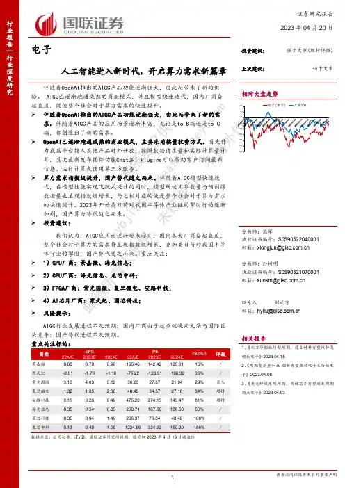
电子人工智能进入新时代,开启算力需求新篇章伴随着OpenAI 推出的AIGC 产品功能逐渐强大,由此而带来了新的供给。
AIGC 已逐渐跑通成熟的商业模式,并且模型快速迭代,国内厂商奋起直追,促使整个社会对于算力需求的快速提升。
➢ 伴随着OpenAI 推出的AIGC 产品功能逐渐强大,由此而带来了新的需求。
伴随着AIGC 产品的应用场景逐渐丰富,无论是to B 端还是to C 端,都创造出了新的需求。
➢ OpenAI 已逐渐跑通成熟的商业模式,主要采用按量收费方式。
首先作为底层平台接入其他产品对外开放,按照数据请求量和实际计算量计算。
其次最新发布插件功能ChatGPT Plugins 可以帮助客户访问最新信息、运行计算或使用第三方服务。
➢ 算力需求指数级提升,国产替代随之而来。
伴随着AIGC 模型快速迭代,在模型性能实现飞跃式提升的同时,模型所使用参数量与预训练数据量也呈现指数级增长,与之相对应的便是整个社会对于算力需求的快速提升。
2023年开始美日荷对我国半导体产业链的掣肘行动逐渐加剧,国产算力替代随之而来。
➢ 投资建议:我们认为,AIGC 应用面逐渐越来越广,国内各大厂商奋起直追,整个社会对于算力的需求将呈现指数级增长,叠加美日荷对我国半导体行业的掣肘,国产替代随之而来。
重点关注: ➢ 1)GPU 厂商:景嘉微、海光信息;➢ 2)CPU 厂商:海光信息、龙芯中科;➢ 3)FPGA 厂商:紫光国微、复旦微电、安路科技;➢ 4)AI 芯片厂商:寒武纪、国芯科技;➢ 风险提示:AIGC 行业发展进程不及预期;国内厂商由于起步较晚而无法与国际巨头竞争;国产替代进程不及预期。
重点关注标的:简称EPS PE CAGR-3评级22A/E 2023E 2024E 22A/E 2023E 2024E 景嘉微 0.68 0.79 0.90 165.46 142.42 125.01 15% / 寒武纪 -2.91 -1.79 -1.19 -76.22 -123.91 -186.39 36% / 紫光国微 3.10 4.03 5.12 36.23 27.87 21.94 29% 买入复旦微电 1.32 1.85 2.36 48.45 34.57 27.10 34% 增持 安路科技 0.15 0.26 0.49 475.20 274.15 145.47 81% 增持 海光信息 0.35 0.54 0.85 258.71 167.69 106.53 56% / 国芯科技 0.35 0.941.49 206.37 76.84 48.48 106% /数据来源:公司公告,iFinD ,国联证券研究所预测,股价取2023年4月19日收盘价 证券研究报告 2023年04月20日投资建议: 强于大市(维持评级)上次建议: 强于大市相对大盘走势Table_First|Table_Author 分析师:熊军执业证书编号:S0590522040001 邮箱:*****************.cn分析师:孙树明执业证书编号:S0590521070001 邮箱:**************.cn联系人 刘欢宇邮箱:**************.cn相关报告1、《北方华创业绩超预期,设备材料有望维持高增长电子》2023.04.152、《周期复苏叠加AI 创新有望推动电子大行情电子》2023.04.083、《美光释放乐观预期,存储芯片有望迎来周期拐点电子》2023.04.03本报告仅供 y bj ie s ho u @e a s t m o n e y .c o m 邮箱所有人使用,未经许可,不得外投资聚焦研究背景北京时间3月14日晚间,谷歌宣布将进一步在其产品中引入人工智能(AI )技术,北京时间2023年3月15日凌晨,OpenAI 宣布正式推出GPT-4。


Instructions for UseVivaspin® 6 and 20Vivaspin® 6 and 20 3K, 5K, 10K, 30K, 50K, 100K, 300K, 1000K and 0.2 µm devices are for research use only; not for use in diagnostic procedures85030-511-57For German, French, Italian, and Spanish manuals, please go to /Vivaspin6ContentsInstructions for Use Vivaspin ® 6 and 20 3Contents1 Vivaspin ® 6 and 20 – Introduction . . . . . . . . . . . . . . . . . . . . . . . . . . . . . . . . . . . . . . . .41.1 Storage Conditions | Shelf Life ........................................41.2 Introduction...........................................................41.3 Centrifugal Operation ................................................51.4 Pressurised Operation ................................................52 Equipment Required . . . . . . . . . . . . . . . . . . . . . . . . . . . . . . . . . . . . . . . . . . . . . . . . . . . . .62.1 Rotor Compatibility ...................................................73 Operation . . . . . . . . . . . . . . . . . . . . . . . . . . . . . . . . . . . . . . . . . . . . . . . . . . . . . . . . . . . . . . . .83.1 In Centrifuge VS6 & 20................................................83.2 Removing the Vivaspin ® 6 body from the filtrate tube ................93.3 Using Gas Pressure (Vivaspin ® 20 only) .............................103.4 Desalting | Buffer Exchange ..........................................113.5 Desalting with Vivaspin ® 20 ...........................................113.6 Vivaspin ® 20 Diafiltration.............................................124 Technical Specifications . . . . . . . . . . . . . . . . . . . . . . . . . . . . . . . . . . . . . . . . . . . . . . . .135 Usage Tips . . . . . . . . . . . . . . . . . . . . . . . . . . . . . . . . . . . . . . . . . . . . . . . . . . . . . . . . . . . . . .155.1 Flow Rate ............................................................155.2 Pre-rinsing ...........................................................155.3 Sanitization of Polyethersulfone Membranes........................155.4 Chemical Compatibility..............................................156 Performance Characteristics . . . . . . . . . . . . . . . . . . . . . . . . . . . . . . . . . . . . . . . . . . . .167 Chemical Compatibility . . . . . . . . . . . . . . . . . . . . . . . . . . . . . . . . . . . . . . . . . . . . . . . . .188 Ordering Information . . . . . . . . . . . . . . . . . . . . . . . . . . . . . . . . . . . . . . . . . . . . . . . . . .209 Product Labeling . . . . . . . . . . . . . . . . . . . . . . . . . . . . . . . . . . . . . . . . . . . . . . . . . . . . . . . .23Vivaspin® 6 and 20 – Introduction1 Vivaspin® 6 and 20 –Introduction1.1 Storage Conditions | Shelf LifeVivaspin® 6 and 20 ultrafiltration spin c olumns should be stored at 15 – 30°C. The devices should be used before the expiry date p rinted on the box.1.2 IntroductionVivaspin® concentrators are disposable ultrafiltration devices for the concen-tration and | or purification of biological samples. Vivaspin® 6 is suitable for sample volumes of 2 – 6 ml and the Vivaspin® 20 can handle s amples up to 20 ml. Both products feature twin vertical membranes for unparalleled speed. Vivaspin® 20 purification alternatives include a diafiltration cup that allows one step r emoval of salts and other contaminating micromolecules, and a gas pressure mode for increased flexibility and even faster p rocessing.The innovative design (US Patent No. 5,647,990, second patent pending), ease of use, speed and exceptional concentrate recoveries are the main features of the c oncentrators.The Vivaspin® 6 and 20 includes 9 different c utoffs (Molecular Weight Cutoff, MWCO):−Vivaspin® 6 & 20 3K device: 3,000 MWCO−Vivaspin® 6 & 20 5K device: 5,000 MWCO−Vivaspin® 6 & 20 10K device: 10,000 MWCO−Vivaspin® 6 & 20 30K device: 30,000 MWCO−Vivaspin® 6 & 20 50K device: 50,000 MWCO4 Instructions for Use Vivaspin® 6 and 20Vivaspin® 6 and 20 – Introduction−Vivaspin® 6 & 20 100K device: 100,000 MWCO−Vivaspin® 6 & 20 100K device: 300,000 MWCO−Vivaspin® 6 & 20 100K device: 1000,000 MWCO−Vivaspin® 6 & 20 100K device: 0.2 µmAll Vivaspin® 6 and 20 devices described above are for research use only and not for use in diagnostic procedures. The Vivaspin® 6 and 20 devices are supplied non-sterile and are for single use only.1.3 Centrifugal OperationVivaspin® concentrators can be used in swing bucket or fixed angle rotors accepting standard conical bottom tubes. In a single spin, solutions can be concentrated in excess of 100 ×. Samples are typically concentrated in10 to 30 minutes with macromolecular recoveries in excess of 95%.The longitudinal membrane orientation and thin channel concentration chamber, provide optimum cross flow conditions even for particle laden solutions; the centrifugal force pulling particles and solids away from the membrane to the bottom of the device. Macromolecules collect in an impermeable concentrate pocket integrally moulded below the membrane surface, thereby eliminating the risk of filtration to dryness.1.4 Pressurised OperationWhen an appropriate centrifuge is unavailable, or for single sample processing, Vivaspin® 20 can be filled with up to 15 ml and pressurised for bench top concentration. For even faster processing, pressure can be combined with centrifugal force. “Pressure-Fugation” is particularly suitable for viscous samples such as serum, or when processing at low temperatures, and generaly when minimum process time is essential.Instructions for Use Vivaspin® 6 and 20 5Equipment Required2 Equipment RequiredA. For use with centrifuge1. Centrifuge with swing bucket or fixed angle rotor (minimum 25°).2. Pasteur or fixed volume pipettes for sample delivery and removal. Device Carrier Required Vivaspin® 615 ml | 17 mm ∅Vivaspin® 2050 ml | 30 mm ∅B. For use with Pressure (Vivaspin® 20 only)1. Vivaspin® 20 Pressure Head (Product No. VCA200).2. Charge Valve for Pressure Head (Product No. VCA005).3. Air Pressure Controller (Product No. VCA002) or equivalent pressureregulator.For use with Pressure and Centrifuge1. All of the equipment shown in A. and B. above.Equipment Required Vivaspin® 6Vivaspin® 20 CentrifugeRotor type Swingbucket FixedangleSwingbucketFixedangleMinimum rotor angle–25°–25°Rotor cavity To fit 15 ml (17 mm)conical bottom tubes To fit 50 ml (30 mm) conical bottom tubes6 Instructions for Use Vivaspin® 6 and 20Equipment RequiredOptional pressure accessories for Vivaspin® 20Air pressure controller (APC) complete withpressure gauge, egulator, over-pressure safetyvalve, female conncetor and 1 m extension line(4 mm pneumatic tubing) with male and femaleconnectors and 1 m of 6 mm inlet tubingProd. no. VCA002Charge valve Prod. no. VCA005 VS20 pressure head Prod. no. VCA200 Concentrate recoveryPipette type Fixed or variablevolume Fixed or variable volumeRecommended tip Thin gel loader type Thin gel loader type2.1 Rotor CompatibilityPlease note: Vivaspin® 20 (30 mm × 116 mm) is designed to fit into rotors that can accommodate Falcon 50 ml conical bottom tubes, e.g. Beckman Allegra 25R with TS-5.1-500 swing-out rotor with BUC 5 buckets and 368327 adaptors; Beckman TA-10.250 25° fixed angle rotor with 356966 adaptors; Heraeus Multifuge 3 S-R with (Heraeus/Sorvall) 75006445 swing out rotor with 75006441 buckets and adaptors for Falcon 50 ml conical bottom tubes.Instructions for Use Vivaspin® 6 and 20 7Operation3 Operation3.1 In Centrifuge VS6 & 201. Select the most appropriate membrane cut-off for your sample. Formaximum recovery select a MWCO at least 50% smaller than themolecular size of the species of interest.2. Fill concentrator with up to maximum volumes shown in table 1.(Ensure screw closure is fully seated.)3. Insert assembled concentrator into centrifuge (when fixed angle rotors areused, angle concentrator so that the printed window facesupwards | outwards).4. Centrifuge at speeds recommended in table 2, taking care not to exceedthe maximum g force indicated by membrane type and MWCO.5. Once the desired concentration is achieved, (see table 3a and 3b for guideto concentration times), remove assembly and recover sample from the bottom of the concentrate pocket with a pipette.8 Instructions for Use Vivaspin® 6 and 20OperationRemoving the Vivaspin® 6body from the filtrate tubeInstructions for Use Vivaspin® 6 and 20 9Operation3.4 Desalting | Buffer Exchange1. Concentrate sample to desired level.2. Empty filtrate container.3. Refill concentrator with an appropriate solvent.4. Concentrate the sample again and repeat the process until theconcentration of contaminating microsolute is sufficiently reduced.Typically, 3 wash cycles will remove 99% of initial salt content.3.5 Desalting with Vivaspin® 20Salts and contaminants can be removed in a single step when using the special diafiltration cup available with the Vivaspin® 20. This is due to the constant washing action (constant volume dialfiltration), of the buffer solution in the cup as it replaces solvent and salts passing through the ultrafiltration membrane.1. Place 2 ml sample solution in the concentrator. (Larger volumes can bedesalted by first concentrating down to 2 ml and decanting filtrate).2. Empty filtrate container.3. Insert diafiltration cup into concentrator and fill with 10 ml deionised wateror buffer solution. Re-fit blue lid over the diafiltration cup.4. Repeat concentration process; over 98% of salts will be removed in thisstep.5. Remove diafiltration cup and recover concentrated and purified sample.Operation3.6 Vivaspin® 20 Diafiltration−Diafiltration cup is filled with buffer solution(Product No: VSA005).−During concentration, solvent in sample iscontinuously replaced by fresh buffer solution.−Salts and contaminants are progressivelycleared through membrane and into filtratevessel.Technical Specifications4 Technical Specifications Table 1: Technical SpecificationsVivaspin® 6Vivaspin® 20 Concentrator capacitySwing bucket rotor 6 ml20 mlFixed angle rotor 6 ml14 mlWith pressure head–15 ml DimensionsTotal Length122 mm–116 mm125 mm with pressure headWidth17 mm30 mmActive membrane area 2.5 cm² 6.0 cm²Hold up volume ofmembrane<10 µl<20 µlDead stop volume*30 µl50 µlMaterials of constructionConcentrator body Polycarbonate PolycarbonateFiltrate vessel Polycarbonate Polycarbonate Concentrator cap Polypropylene Polypropylene Pressure head–Acetal/aluminium Membrane Polyethersulfone Polyethersulfone* D ead stop volume as designed in moulding tool. This volume may vary depending on sample, sample concentration, operation temperature and centrifuge rotor.Technical SpecificationsTable 2: Recommended Spin Speed (xg)Vivaspin® 6Swing Bucket Fixed Angle Membrane max max3–50,000 MWCO PES4,0008,000>100,000 MWCO PES4,0006,000 Vivaspin® 20Centrifuge Pressure-FugeRotor SwingBucket FixedAngleS wing Bucket(5 bar max)Membrane max max max 3–50,000 MWCO PES4,0006,0003,000 >100–300,000 MWCOPES3,0006,0002,000Usage Tips5 Usage Tips5.1 Flow RateFiltration rate is affected by several parameters, including MWCO, porosity, sample concentration, viscosity, centrifugal force and temperature. Expect significantly longer spin times for starting solutions with over 5% solids. When operating at 4°C. flow rates are approximately 1.5 times slower than at 25°C. Viscous solutions such as 50% glycerine will take up to 5 times longer to concentrate than samples in a predominantly buffer solution.5.2 Pre-rinsingMembranes fitted to Vivaspin® concentrators contain trace amounts of Glycerine and Sodium azide. Should these interfere with analysis they can be removed by rinsing fill volume of buffer solution or deionised water through the concentrator. Decant filtrate and concentrate before processing sample solution. If you do not want to use the pre-rinsed device immediately, store it in the refrigerator with buffer or water covering the membrane surface. Please do not allow the membrane to dry out.5.3 Sanitization of Polyethersulfone Membranes Polyethersulfone membranes should not be autoclaved as high temperatures will substantially increase membrane MWCO. To sanitize, use a 70% ethanol solution or sanitizing gas mixture.5.4 Chemical CompatibilityVivaspin® concentrators are designed for use with biological fluids and aqueous solutions. For chemical compatibility details, refer to table 4.Performance Characteristics6 Performance Characteristics Table 3a: Typical Performance Characteristics Vivaspin® 6Time to concentrate up to 30x [min .] at 20°Cand solute recovery %Rotor Swing bucket25° Fixed angle Start volume 6 ml 6 mlMin.Rec.Min.Rec. Cytochrome c 0.25 mg/ml (12,400 MW)3,000 MWCO PES––9097% BSA 1.0 mg/ml (66,000 MW)5,000 MWCO PES2098%1298% 10,000 MWCO PES1398%1098% 30,000 MWCO PES1298%997% IgG 0.25 mg/ml (160,000 MW)30,000 MWCO PES1896%1595% 50,000 MWCO PES1796%1495% 100,000 MWCO PES1591%1291% Latex beads 0.004% in DMEM +10% FCS (0.055 μm)30,000 MWCO PES––2599% Latex beads 0.004% in DMEM +10% FCS (0.24 μm)1,000,000 MWCO PES––499% Yeast 1.0 mg/ml (S. Cerevisiae)0.2 μm PES497%397%Performance CharacteristicsTable 3b: Typical Performance Characteristics Vivaspin® 20Time to concentrate up to 30x [min .] at 20°Cand solute recovery %Mode Centrifuge Centrifuge Bench top Press-fugePressure Swing bucket Rotor Swing bucket25° FixedangleStart volume20 ml14 ml10 ml10 mlMin. Rec.Min. Rec.Min. Rec.Min. Rec. Cytochrome c 0.25 mg/ml (12,400 MW)11097%18096%6096%––3,000MWCO PESBSA 1.0 mg/ml (66,000 MW)2399%2999%5098%1498% 5,000MWCO PES10,0001698%1798%3297%897% MWCO PES1398%1598%3297%897% 30,000MWCO PESIgG 0.25 mg/ml (160,000 MW)2797%2095%4694%1397% 30,000MWCO PES2796%2295%4693%1396% 50,000MWCO PES2591%2090%4288%1294% 100,000MWCO PESChemical CompatibilityLatex beads 0.004% in DMEM +10% FCS (0.055 µm)2099%3599%1099%––300,000MWCO PESLatex beads 0.004% in DMEM +10% FCS (0.24 µm)1,000,000499%1299%499%MWCO PESYeast 1.0 mg/ml (S. Cerevisiae)0.2 µm PES1595%595%2095%295% 7 Chemical CompatibilityTable 4: Chemical Compatibility (2 hr contact time)Solutions PESCompatible pH range pH 1–9Acetic Acid (25.0%)OKAcetone (10.0%)NOAcetonitrile (10.0%)NOAmmonium Hydroxide (5.0%)?Ammonium Sulphate (saturated)OKBenzene (100%)NOn-Butanol (70%)OKChloroform (1.0%)NODimethyl Formamide (10.0%)?Dimethyl Sulfoxide (5.0%)OKChemical CompatibilitySolutions PESCompatible pH range pH 1–9Ethanol (70.0%)OKEthyl Acetate (100%)NO Formaldehyde (30%)OKFormic Acid (5.0%)OKGlycerine (70%)OKGuanidine HCI (6 M)OK Hydrocarbons, aromatic NO Hydrocarbons, chlorinated NOHydrochloric Acid (1 M)OKImidazole (500 mM)OKIsopropanol (70%)OKLactic Acid (5.0%)OK Mercaptoethanol (10 mM)OKMethanol (60%)?Nitric Acid (10.0%)OKPhenol (1.0%)?Phosphate Buffer (1.0 M)OKPolyethylene Glycol (10%)OKPyridine (100%)?Sodium Carbonate (20%)?Sodium Deoxycholate (5.0%)OKSodium Dodecylsulfate (0.1 M)OKOrdering InformationSolutions PESCompatible pH range pH 1–9Sodium Hydroxide NOSodium Hypochlorite (200 ppm)?Sodium Nitrate (1.0%)OKSulfamic Acid (5.0%)OK Tetrahydrofuran (5.0%)NOToluene (1.0%)NO Trifluoroacetic Acid (10%)OKTween®* 20 (0.1%)OKTriton®** X-100 (0.1%)OKUrea (8 M)OKOK = Acceptable ? = Questionable NO = Not recommended* Tween® is a registered trademark of ICI Americas Inc.** Triton® is a registered trademark of Union Carbide Corp.8 Ordering InformationVivaspin® 6 Polyethersulfone Qty per box Prod. No. 3,000 MWCO25VS0691 3,000 MWCO100VS0692 5,000 MWCO25VS0611 5,000 MWCO100VS0612Ordering Information10,000 MWCO25VS060110,000 MWCO100VS060230,000 MWCO25VS062130,000 MWCO100VS062250,000 MWCO25VS063150,000 MWCO100VS0632100,000 MWCO25VS0641100,000 MWCO100VS0642300,000 MWCO25VS0651300,000 MWCO100VS06521,000,000 MWCO25VS06611,000,000 MWCO100VS06620.2 µm25VS06710.2 µm100VS067225VS06S1Starter pack (5 of each 5 K, 10 K, 30 K,50 K, 100 K)Vivaspin® 20 Polyethersulfone Qty per box Prod . no .3,000 MWCO12VS20913,000 MWCO48VS20925,000 MWCO12VS20115,000 MWCO48VS201210,000 MWCO12VS200110,000 MWCO48VS2002Instructions for Use Vivaspin® 6 and 20 21Ordering Information30,000 MWCO12VS2021 30,000 MWCO48VS2022 50,000 MWCO12VS2031 50,000 MWCO48VS2032 100,000 MWCO12VS2041 100,000 MWCO48VS2042 300,000 MWCO12VS2051 300,000 MWCO48VS2052 1,000,000 MWCO12VS2061 1,000,000 MWCO48VS2062 0.2 µm12VS2071 0.2 µm48VS2072 Starter pack (2 of each 5 K, 10 K, 30 K,12VS20S1 50 K, 100 K, 0.2 µm)Vivaspin® 20 accessories Qty per box Prod. no. Air pressure controller (APC)1VCA002 Charge valve for pressure head1VCA005 Diafiltration cups12VSA005 Female connector1VCA010 Male connector1VCA011 4 mm OD pneumatic tube (3 m)1VCA012 Vivaspin® 20 pressure head1VCA20022 Instructions for Use Vivaspin® 6 and 20Product Labeling9 Product LabelingThe following table defines the symbols found on Vivaspin® 6 & 20 device labels.SymbolDefinitionCatalogue numberDo not reuseUse byBatch codeDate of manufactureManufacturerTemperature limitationNon-sterile productInstructions for Use Vivaspin® 6 and 20 23Last updated:The information and figures contained in these instructions correspond to the version date specified below.Sartorius reserves the right to make changes to the technology, features, specifications and design of the equipment without notice.Masculine or feminine forms are used to facilitate legibility in these instructions andalways simultaneously denote the other gender as well.Copyright notice:This instruction manual, including all of its components, is protected by copyright.Any use beyond the limits of the copyright law is not permitted without our approval.This applies in particular to reprinting, transla-tion and editing irrespective of the type of media used.© Sartorius GermanySartorius Stedim Lab Ltd.Sperry Way, Stonehouse ParkGL10 3UT Stonehouse, Gloucestershire, UK Phone: +44 1453 © 2021 Sartorius Stedim Lab Ltd.Sperry Way, Stonehouse ParkGL10 3UT Stonehouse, Gloucestershire, UK AM | Publication No.: SLU6092-e21061306 | 2021。
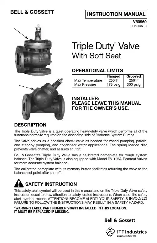
INSTRUCTION MANUAL BELL &GOSSETTV50960REVISION C H H Bell &GossettTriple Duty ®Valve With Soft SeatOPERATIONAL LIMITS Flanged Grooved Max Temperature 250°F 250°F Max Pressure 175 psig 300 psigINSTALLER:PLEASE LEAVE THIS MANUAL FOR THE OWNER’S USE.DESCRIPTIONThe Triple Duty Valve is a quiet operating heavy-duty valve which performs all of the functions normally required on the discharge side of Hydronic System Pumps.The valve serves as a nonslam check valve as needed for zoned pumping, parallel and standby pumping, and condenser water applications. The spring loaded disc prevents valve chatter, and assures shutoff.Bell &Gossett’s Triple Duty Valve has a calibrated nameplate for rough system balance. The Triple Duty Valve is also equipped with Model RV-125A Readout Valves for more accurate system balance.The calibrated nameplate with its memory button facilitates returning the valve to the balance set point after shutoff.SAFETY INSTRUCTIONThis safety alert symbol will be used in this manual and on the Triple Duty Valve safety instruction decal to draw attention to safety related instructions. When used, the safety alert symbol means ATTENTION!BECOME ALERT! YOUR SAFETY IS INVOLVED!FAILURE TO FOLLOW THE INSTRUCTIONS MAY RESULT IN A SAFETY HAZARD.*WARNING LABEL PART NUMBER V56871 INSTALLED IN THIS LOCATION.IT MUST BE REPLACED IF MISSING.2INSTALLATION INSTRUCTIONSBell &Gossett Triple Duty Valves must be installed on the discharge side of the system pump with the stem pointing up to facilitate proper seating of the valve disc. See installation drawing on page 4.NOTE:Before turning stem of 4" and larger valves, make sure the set screw in the packing nut is loose.OPERATING INSTRUCTIONS1.Place a wrench on the wrench flats on top of 3D Valve stem and open 3D Valve to the 100%open position. Stem position (amount 3D Valve is open or closed) can be read by the position of the indicator ring through the nameplate slot.2.Energize the Zone, Circuit and/or system pump(s) as applicable so that fluid is flowing through the 3D Valve. Make sure that all air has been vented from system.ing Bell &Gossett Model RP-250B readout probes, attach a Bell &Gossett differential pressure readout kit to the readout valves on the 3D Valves.4.Read the differential pressure across the 3D Valve.5.Refer to the appropriate 3D Valve performance curve or Cv rating table to determine flow based on the results from step “4” and the percent stem rise.6.If the GPM does not agree with the specified (required) GPM, close the 3D Valve accordingly. Repeat steps “4”, “5” and “6” until the required results have been achieved.7.After establishing the required balance set point, position the white rubber memory button so that the arrow, when in the three or nine o’clock posi-tion, points to the stem rise mark on the calibrated nameplate.SERVICE INSTRUCTIONSA.Valve leaking at the packing nut-turn packing nut clockwise until the leak stops.WARNING: Hot water leakage can occur from readout valves dur-ing probe insertion and during hookup of readout kit. Follow the instructions in instruction manuals supplied with readout probes and readout kits for safe use. Keep eyes protected with safety glasses. Make sure that readout valves are not leaking before removing safety cap.Failure to follow this instruction can result in serious personal injury or death and property damage.WARNING: Hot fluid leaking from valve can cause burns. Avoid con- tact with leaking fluid while servicing valve. Failure to follow this instruc-tion can result in serious personal injury or death and property damage.IMPORTANT: If system balancing at less than 50% stem rise and this is the primary balance valve, ASHRAE Standard 90.1 and Bell &Gossett recommend trimming the impeller to the necessary system design flow.This will reduce electrical energy consumption and comply with the National Energy Building Code Standard.IMPORTANT: To avoid noise problems and possible damage to 3D valve, do not exceed 25 feet of pressure drop across 3D valve.3B.If leaking persists –1.Note the position of the valve opening (%Stem Rise), if the memory button is missing.2.Turn the valve stem fully counterclockwise until the stem resists addi-tional turning.3.Remove the packing nut (located at the base of stem) by turning it counterclockwise.4.Remove old packing.5.Repack as required.6.Replace the packing nut and tighten as required.7.Reposition the valve stem per observation in Step #1.C.Valve leaking at the Bonnet gasket area – tighten (as required) until the leakage stops.D.If leaking persists, or when replacing valve internals –1.Loosen the bonnet nuts or threaded bonnet cap (depending on valve size) and remove the bonnet assembly with the valve stem attached.2.Remove the old gasket and clean up the gasket surface on the body and bonnet.3.Inspect the valve internals for signs of corrosion or erosion (wire draw across the seat). If damaged, they must be replaced to function properly.4.If the valve appears to be in serviceable condition, install a new gasket and replace bonnet assembly.5.Secure the bonnet.6.Return the system to its normal operating mode.NOTE:If leakage occurs at the bonnet gasket area, tighten (as required) until the leakage stops. Refer to 5 above.E.Replacing a damaged nameplate –1.Note the position of the valve opening (%Stem Rise).2.Loosen and remove (2) screws.3.Replace the old nameplate with one that has the same 6 digit part number as the one removed.4.Replace and tighten the screws making sure the position of the valve opening (%Stem Rise) lines up with the indicating ring near the top of the cone on the bonnet, identically as the old nameplate.WARNING: Hot system fluid can be hazardous. Isolate the Triple Duty Valve from the system with shutoff valves or drain the system.Allow isolated system and Triple Duty Valve to cool to approximately 100°F . Reduce isolated system pressure to zero. Leave drain open. Failure to follow this instruction can result in serious personal injury or death and property damage.CAUTION: Improper tightening of bonnet can cause damage to bonnet and gasket. If bonnet is bolted, tighten bolts in a crisscross pattern. Failure to follow this instruction can result in property damage and/or moderate personal injury.WARNING: Check for proper sealing when using as an isolation valve. If seat is not sealing properly, liquid will continue to flow from drain valves. In this case valve must be isolated from system pressure and inspected for seat or disc damage. Replace as necessary. Failure to follow this instruction can result in serious personal injury or death and property damage.Bell &Gossett© COPYRIGHT 1989, 2001 BY ITT INDUSTRIES, INC.DIN ISO 9001TUV CERTISO 9001 CertifiedPRINTED IN U.S.A. 12-01USABell &Gossett8200 N. Austin Avenue Morton Grove, IL 60053 Phone: (847) 966-3700 Facsimile: (847) 966-9052 CAUTION: Improper valve stem orientation can cause damage to 3D valve or improper system operation. For proper installation, valve stem must point up above horizontal plane. Failure to follow this instruction can result in property damage and/or moderate personal injury.ARROW INDICATES DIRECTION OF FLOWRV-125A Readout Valve The RV-125 Readout Valve is equipped with an integral EPT Check Valve designed to minimize system fluid loss when setting up to monitor pumps, heat exchangers, valves, etc., handling hot or cold water.RP-250B Readout Probe These Readout Probes are designed for use with the B&G RV-125A R e a d o u t Valve.。
gradio then方法什么是Gradio?Gradio是一个开源的Python库,旨在为机器学习开发人员提供一个快速创建和部署自定义界面的简单方式。
使用Gradio,开发人员可以通过几个简单的步骤创建一个交互式界面,让用户可以轻松地与他们的机器学习模型进行交互。
Gradio的设计目标是让界面创建变得简单易用,并且不需要任何前端开发经验。
Gradio的核心概念是将用户界面的创建拆分为两个主要步骤:定义输入和定义输出。
在这两个步骤中,开发人员可以使用各种不同的函数和参数来自定义他们所需的界面功能。
让我们一步一步地看看如何使用Gradio 将一个机器学习模型包装成一个交互式界面。
第一步:安装Gradio首先,我们需要安装Gradio库。
可以使用以下命令在终端中安装Gradio:pip install gradio确保在安装之前已经安装了Python和pip。
第二步:导入必要的库和模型在开始创建界面之前,我们首先需要导入必要的库和模型。
假设我们有一个训练好的图像分类模型,我们想要将其包装到一个交互式界面中。
我们可以使用以下代码导入所需的库和模型:pythonimport gradio as grimport tensorflow as tf# Load the pre-trained modelmodel = tf.keras.models.load_model("my_model.h5")请注意,这里我们使用了TensorFlow库来加载我们的模型,但是Gradio 与任何机器学习库或框架都兼容。
只需使用适当的代码将模型加载到变量中即可。
第三步:定义输入和输出函数接下来,我们需要定义输入和输出函数。
输入函数定义了用户可以输入什么样的数据,而输出函数定义了模型计算出的结果如何显示给用户。
在我们的示例中,我们将接收用户上传的图像,并返回模型对图像的分类结果。
pythondef classify_image(input_image):# Preprocess the image if necessaryprocessed_image = preprocess_image(input_image)# Make predictions using the pre-trained modelpredictions = model.predict(processed_image)# Convert predictions to human-readable labelslabels = convert_predictions(predictions)return labelsdef preprocess_image(input_image):# Preprocess the input image (e.g., resize, normalize)processed_image = ...return processed_imagedef convert_predictions(predictions):# Convert the model's predictions to human-readable labelslabels = ...return labels在输入函数中,我们首先对图像进行了预处理,以便将其传递给模型进行预测。
SOBEY操作手册(非编工作站)前言感谢您选用成都索贝数码科技股份有限公司(Sobey Digital Technology Co., Ltd)的ENE—E-Net编辑网络系统。
索贝E-Net是索贝公司全力打造的制播一体化网络新产品,是一个具有新闻共享、制作、播出、小媒资管理和网络管理的全数字环境的智能化新闻节目制播网络系统。
ENE是索贝E-Net系统中的制作部分,它能支持电视台新闻业务的运作,并承担电视台大部分新闻节目生产任务。
系统实现收录和自采新闻节目素材的全台共享,充分利用计算机多媒体技术和网络技术,全面提高电视台新闻节目的制作水平和播出效率。
索贝E-NET非线性编辑网络系统是我公司自主开发的一套全中文的非线性广播级节目制作系统,它能广泛地适用于广播电视单位,各种电视教育以及各类广告的制作。
E-NET非编系统采用数字视频技术发展方向的MPEG 2压缩方式,将编辑、字幕、节目包装“三位一体”化,并以完善的素材、节目管理机制全面兼容ENC网络,是索贝公司为新开发的新一代全新的非线性编辑系统。
本手册适用于系统操作人员、电视台编辑、记者。
本手册的主要目的是对ENE软件的实际操作提供指南。
本文件包含有关【索贝媒体资产管理系统】的最新重要信息。
该手册及其中所说明的软件受许可协议的约束,只能在符合许可协议中所述的条件下才可使用和复制。
该手册的内容仅供参考,以后若有更动,恕不给予通知,不应将此理解为Sobey Digital Corporation 的责任。
Sobey Digital Corporation 不需对可能出现在该手册中的错误担任何责任或义务。
除了许可协议中所允许的范围外,未经Sobey Digital Corporation 事先书面同意,不得将这份手册的任何部分进行复制、存贮在检索系统中、或以任何形式或手段(电子、机械、录制等等)传送。
请记住,您准备纳入您项目中的现存的插图或图像可能受版权法保护。
SENO Essential 快速操作手册目录1.开机登陆界面2.输入患者信息3.摆位4.压迫板的调整5.图像采集6.图像编辑7.关闭检查传输图像8.查看历史图像9.删除图像&患者信息10.关机操作11.附表1.开机登陆界面❶按下开机键❷输入“sdc”,按回车键❹进入登陆界面❸分别输入用户名及密码,点击“Login”操作2.1 输入患者信息(配有 PACS/RIS 系统)❶点击进入患者信息界面❷点击刷新工作列表❸可通过ID 或 Last name 进行快速查找❹用鼠标选中要检查患者2.2 输入患者信息(未配有 PACS/RIS 系统)❶点击进入患者信息界面❷点击建立新患者❸必须填写“Last name & ID”(年龄可在First name 中添加)❹填写患者信息后,点击进入采集界面2.3 假体植入患者PVi功能的使用(☆此功能为选配)在患者登记卡里,将“Implant present ”标记设置为“Yes”,则启用 PVi 植入物功能。
Tips:假体植入患者曝光注意事项1.对于假体植入物曝光,推荐使用手动模式2.在不取出植入物的情况下,应使用建议的采集参数(见附表2)3.若取出了植入物,则可使用AOP模式4.当使用 FOV 小于 19X23 的放大及点压,PVi 不能使用3.摆位❶进入采集界面❷进行患者摆位4.压迫板的调整(旋转此钮可用于压迫板的更换)压迫板点击下方按钮可退出滤线栅,用于更换放大平台或三维穿刺装置。
4.1 偏中心压迫压迫板的调整当使用 19X23 滑动压迫板拍摄腺体左/右位时,需将压迫板滑动至压迫架的左/右侧。
(图片为用 19X23 滑动压迫板拍摄 RMLO 位时的压迫板设置)5.1 图像采集(自动曝光模式)Tips :不能曝光常见原因 1.压迫力度:小于 3daN 以下 2.压迫厚度小于 2cm 或大于 8cm 3.常规拍摄没有选择大焦点 4.没有选择“R/L ”键自动曝光模式 (AOP 曝光模式)CNT : 对比度优先 (保证成像对象的最佳对比度) STD : 标准模式 (在对比度和剂量之间取得平衡) DOSE :剂量优先 (低放射剂量,适合大量体检)手动曝光模式显示KV ,mAs : 压迫厚度大于8cm 或小于3cm 的乳腺;假体及标本❶ 点击此键,顺序出现以下四种曝光模式 ❷ 同时按住维持约5秒或手闸曝光5.2 图像采集(手动曝光模式) Tips :手动曝光模式适用于压迫厚度大于 8cm 或小于 3cm 的乳腺、假体及标本。