LR MQPS 0-1 英国船级社 焊接工艺评定与无损检测
- 格式:pdf
- 大小:249.66 KB
- 文档页数:12
中国船级社无损检测证书(原创版)目录一、中国船级社无损检测证书简介二、无损检测人员资格鉴定与认证规范三、无损检测证书的作用和意义四、申请无损检测证书的流程五、无损检测证书的有效性和延续正文一、中国船级社无损检测证书简介中国船级社(China Classification Society,简称 CCS)成立于 1956 年,是我国唯一的船舶检验机构,负责对船舶和海洋工程设备进行检验、认证和监管。
无损检测证书是 CCS 颁发的一种专业资质证书,用于证明持证人员具备一定的无损检测能力,可以在船舶和海洋工程领域从事相关工作。
二、无损检测人员资格鉴定与认证规范为了保证无损检测人员的专业素质和能力,CCS 制定了《中国船级社无损检测人员资格鉴定与认证规范》。
该规范对无损检测人员的资格鉴定、认证、培训和考核等方面的要求进行了详细规定。
1.资格鉴定与认证范围:适用于船舶和海洋工程领域的无损检测人员,包括磁粉检测、射线检测、超声检测、涡流检测等。
2.资格鉴定与认证等级:分为三个等级,分别是初级、中级和高级。
不同等级对应不同的岗位和职责。
3.资格鉴定与认证程序:包括报名、资格审查、培训、考核和颁发证书等环节。
4.培训和考核:培训内容涵盖无损检测的基本原理、方法和应用,以及相关标准和法规。
考核主要通过理论考试和实践操作考试进行。
三、无损检测证书的作用和意义无损检测证书对于持证人员和船舶行业都具有重要意义:1.对于持证人员:证书是证明其具备一定无损检测能力的凭证,有助于提高个人素质和就业竞争力,拓宽职业发展渠道。
2.对于船舶行业:证书有助于规范无损检测市场,提高检测质量,保障船舶和海洋工程设备的安全运行。
四、申请无损检测证书的流程申请无损检测证书的具体流程如下:1.报名:持证人员需填写报名表,并提交相关材料,如身份证、学历证明等。
2.资格审查:CCS 对报名人员进行资格审查,确认是否符合报名条件。
3.培训:通过资格审查的人员需参加 CCS 组织的无损检测培训。
浅谈对WPS和PQR的理解和分析技术质量部伍磊摘要:焊接工艺评定报告(英文缩写PQR,取自英文焊接工艺评定报告Welding procedure qualification record)中后三词的词头,70年代自国外引进以来,已是压力容器、压力管道制造、安装、修理中必不可少的工作程序,是评定制造、安装、修理单位焊接技术水平(资格)的依据。
由于其科学、合理、严格的评定过程,也被钢结构、贮罐制造和安装等行业采用。
虽然叫法有些不同(有的叫焊接工艺试验),但方法和要求是基本一致的。
焊接工艺规程(英文缩写WPS取自英文Welding procedure specification的词头)50年代自苏联引进。
改革开放以来,引进西方的WPS经过多年消化、创新,目前我国焊接生产、工程安装中已广泛编制WPS用于指导生产。
WPS与PQR的关系,前者是后者的编制依据。
关键词:焊接工艺评定报告;焊接工艺规程;材料;焊接;试验0、前言在压力管道、船舶等产品的制造中,经常会遇到两种形式的焊接文件,即焊接工艺文件(WPS)和焊接工艺评定报告(PQR)。
在一个工程开工之前,监理和业主往往要求制造商出示此类文件。
然而很多厂家和部门常常为其所困,采用模糊、拖延的方法来应付,也有的部门说不清对方到底需要的是什么资料,使生产和经营处于非常被动的地位。
国内外焊接制造规范都要求企业进行焊接工艺评定,以验证企业焊制符合标准接头的基本能力(最低门槛指标) 。
一般情况下,焊接工艺评定由企业的技术部门编制,根据产品需求,按照有关标准如美国的ASME 第Ⅸ篇、欧洲EN 288—3及我国的JB 4708-2000等标准执行.遵照标准每种重要参数的改变,如焊接方法、母材类别(组号)、预热温度、热处理温度、焊接热输入超出规定的范围,都要进行焊接工艺评定试验。
由于影响焊接接头力学性能的工艺参数众多,很多企业都积累了大量的焊接工艺评定报告。
中海金洲一直致力于研究有效利用和管理焊接工艺文件及焊接工艺评定报告的方法,以此来提高公司产品的焊接质量及生产效率,降低生产成本,从而大幅度提高企业的经济效益。
某某双相不锈钢压力容器项目焊接工艺评定计划编号PWPS-****编制审核************公司2017年**月**日双相不锈钢压力容器项目按PD5500-2015《非直接受火焰焊接压力容器》设计、建造,由英国劳氏船级社LR监检认可。
按照ISO 15614-1《金属材料焊接工艺规程及评定》要求,编制本焊接工艺计划书提交LR,用以指导完成焊接工艺认可试验。
按预先制定PWPS进行施焊,根据合格的焊接工艺认可试验报告(WPQR),对PWPS焊接工艺修改完善后,经LR正式审核批准形成正式的WPS,用以指导产品生产焊接。
一、计划进行的焊接工艺评定项目1.工艺评定(一)评定代号:PWPS-****焊接方法:手工钨极氩弧焊(GTAW)焊接设备:S350林肯多功能焊机母材:BS EN 10028-7 1.4462焊接试板规格:5mm×300mm×800mm焊接位置及接头形式:平焊、(坡口)对接焊焊接材料:CTS-2209/Ar ¢2.0焊接位置:立向上主要检测项目:①无损检测:100% RT,100% PT②力学性能试验:硬度测试试样数量:1件横向拉伸试验试样数量:2件弯曲试验试样数量:4件(2面弯+2背弯)冲击试验:免于冲击③抗腐蚀试验:金相检查(不小于200倍)铁素体含量测定腐蚀试验(按ASTM G48方法)2.工艺评定(二)评定代号:PWPS-***焊接方法:手工焊条电弧焊(SMAW)焊接设备:S350林肯多功能焊机母材:BS EN 10028-7 1.4462焊接试板规格:10mm×300mm×800mm焊接位置及接头形式:平焊、(坡口)对接焊焊接材料:CES-2209 ¢2.5/¢3.2焊接位置:立向上主要检测项目:①无损检测:100% RT,100% PT②力学性能试验:硬度测试试样数量:1件横向拉伸试验试样数量:2件弯曲试验试样数量:4件(2面弯+2背弯)冲击试验(试验温度取-20℃):焊缝中心1组熔合线1组熔合线+2mm 1组熔合线+5mm 1组③抗腐蚀试验:金相检查(不小于200倍)铁素体含量测定腐蚀试验(按ASTM G48方法)3.工艺评定(三)评定代号:PWPS-*****焊接方法:药芯焊丝电弧焊(FCAW)焊接设备:S350林肯多功能焊机母材:BS EN 10028-7 1.4462焊接试板规格:10mm×300mm×800mm焊接位置及接头形式:立焊、(坡口)对接焊焊接材料:CFS-2209/ CO2 ¢1.2焊接位置:立向上主要检测项目:①无损检测:100% RT,100% PT②力学性能试验:硬度测试试样数量:1件横向拉伸试验试样数量:2件弯曲试验试样数量:4件(2面弯+2背弯)冲击试验(试验温度取-20℃):焊缝中心1组熔合线1组熔合线+2mm 1组熔合线+5mm 1组③抗腐蚀试验:金相检查(不小于200倍)铁素体含量测定腐蚀试验(按ASTM G48方法)4.工艺评定(四)评定代号:PWPS-*****焊接方法:手工焊条电弧焊(SMAW)+药芯焊丝电弧焊(FCAW)组合焊焊接设备:S350林肯多功能焊机母材:BS EN 10028-7 1.4462焊接试板规格:20mm×300mm×600mm焊接位置及接头形式:平焊、(坡口)对接焊焊接材料:CES-2209 ¢2.5/¢3.2+CFS-2209/CO2 ¢1.2焊接位置:立向上主要检测项目:①无损检测:100%RT,100%PT②力学性能试验:硬度测试试样数量:1件横向拉伸试验试样数量:2件弯曲试验试样数量:4件(侧弯代替)冲击试验(试验温度取-20℃):焊缝中心1组熔合线1组熔合线+2mm 1组熔合线+5mm 1组③抗腐蚀试验:金相检查(不小于200倍)铁素体含量测定腐蚀试验(按ASTM G48方法)5.工艺评定(五)评定代号:PWPS-*****焊接方法:手工焊条电弧焊(SMAW)焊接设备:S350林肯多功能焊机母材:BS EN 10028-7 1.4462+ BS EN 10028-7 1.4404(异种材料)焊接试板规格:10mm×300mm×600mm焊接位置及接头形式:平焊、(坡口)对接焊焊接材料:CES-2209 ¢2.5/¢3.2焊接位置:立向上主要检测项目:①无损检测:100%RT,100%PT②力学性能试验:硬度测试试样数量:1件横向拉伸试验试样数量:2件弯曲试验试样数量:4件(2面弯+2背弯)冲击试验(试验温度取-20℃):焊缝中心1组熔合线1组熔合线+2mm 1组熔合线+5mm 1组③抗腐蚀试验:铁素体含量测定6.工艺评定(六)评定代号:PWPS-*****焊接方法:手工钨极氩弧焊(GTAW)焊接设备:S350林肯多功能焊机母材:BS EN 10028-7 1.4462焊接试板规格:10mm×300mm×800mm焊接位置及接头形式:平焊、(坡口)对接焊焊接材料:CTS-2209/Ar ¢2.0焊接位置:平焊焊后固溶处理主要检测项目:①无损检测:100%RT,100%PT②力学性能试验:硬度测试试样数量:1件横向拉伸试验试样数量:2件弯曲试验试样数量:4件(2面弯+2背弯)冲击试验:免于冲击③抗腐蚀试验:金相检查(不小于200倍)铁素体含量测定腐蚀试验(按ASTM G48方法)7.工艺评定(七)评定代号:PWPS-*****焊接方法:手工焊条电弧焊(SMAW)焊接设备:S350林肯多功能焊机母材:BS EN 10028-7 1.4462焊接试板规格:10mm×300mm×800mm焊接位置及接头形式:平焊、(坡口)对接焊焊接材料:CES-2209 ¢2.5/¢3.2焊后固溶处理焊接位置:平焊主要检测项目:①无损检测:100% RT,100% PT②力学性能试验:硬度测试试样数量:1件横向拉伸试验试样数量:2件弯曲试验试样数量:4件(2面弯+2背弯)冲击试验(试验温度取-20℃):焊缝中心1组熔合线1组熔合线+2mm 1组熔合线+5mm 1组③抗腐蚀试验:金相检查(不小于200倍)铁素体含量测定腐蚀试验(按ASTM G48方法)。
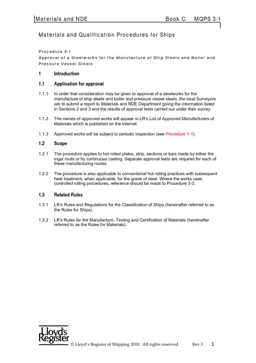
Materials and Qualification Procedures for ShipsProcedure 3-1Approval of a Steelworks for the Manufacture of Ship Steels and Boiler and Pressure Vessel Steels1 Introduction1.1 Application for approval1.1.1 In order that consideration may be given to approval of a steelworks for themanufacture of ship steels and boiler and pressure vessel steels, the local Surveyors are to submit a report to Materials and NDE Department giving the information listedin Sections 2 and 3 and the results of approval tests carried out under their survey. 1.1.2 The names of approved works will appear in LR's List of Approved Manufacturers ofMaterials which is published on the internet.1.1.3 Approved works will be subject to periodic inspection (see Procedure 1-1).1.2 Scope1.2.1 The procedure applies to hot rolled plates, strip, sections or bars made by either theingot route or by continuous casting. Separate approval tests are required for each of these manufacturing routes.1.2.2 The procedure is also applicable to conventional hot rolling practices with subsequentheat treatment, when applicable, for the grade of steel. Where the works usescontrolled rolling procedures, reference should be made to Procedure 3-3.Rules1.3 Related1.3.1 LR's Rules and Regulations for the Classification of Ships (hereinafter referred to asthe Rules for Ships).1.3.2 LR's Rules for the Manufacture, Testing and Certification of Materials (hereinafterreferred to as the Rules for Materials).A B CD2 Information required for approvaldetails2.1 Product2.1.1 The manufacturer is to provide the following product related details:(a) Name and address and brief statementof background indicating whether theworks is new or long established.(b) Types of products and grades of steelmanufactured.(c) Maximum dimensions (includingthickness) and mass of each productwhich can be manufactured.(d) Estimated total annual production ofproducts.finished(e) Products, maximum thicknesses andgrades of steel for which approval isrequired.(f) Details of the steel composition to beused for each grade, including the grainrefining elements to be used and theirspecified limits. This will constitute theapproved composition for the grade.2.2 Details of facilities and procedures2.2.1 The manufacturer is to provide the following details of their facilities and procedures:(a) Details of steelmaking processeswhich are used based upon a processflow chart from raw materials todispatch of final product withexplanation of what is involved witheach step and the number andindividual capacity of steelmakingunits.(b) Details of raw materials used insteelmaking and particularly the sourceand composition of iron and scrapused.(c) Deoxidation practice, detailing alloysused and whether added to thefurnace, ladle or ingot mould.(d) Details of the system employed forcontrol of chemical composition.(e) Dimensions, masses and types ofingots in use, where applicable, andbrief details of method of casting.A B CD(f) Details of any secondary steelmakingprocesses. This to include system usedfor ladle stirring.(g) Brief description of any continuouscasting facilities and details ofassociated procedures includingsequential casting practices.(h) Procedure for obtainingrepresentative ladle samples forchemical analysis including the numbertaken from each ladle and also detailsof the provision made when finalcompositional adjustments are made tothe ladle prior to casting.(j) Dimensions of slabs or billetswhich will be produced.(k) For continuous cast, details ofthe procedures for checkinginternal and external cleanlinessof slabs and billets. This shouldinclude method of sulphurprinting.(l) For products produced fromcontinuously cast stock, proposedminimum amount of hot workingexpressed as the ratio of the cross-sectional area of the billet to the cross-sectional area of the finished rolledproduct.(m) Details of the furnaces used forreheating ingots, slabs or billetsincluding dimensions, type of fuelused, facilities for temperaturemeasurement and control, andarrangements for sampling andcontrolling furnace atmosphere.(n) Procedures for ensuring that cracking arising in the continuous castingprocess is identified, together withdetails of the remedial action that isbeing taken to prevent such crackingfrom remaining in the billet at the rolling stage.(o) Description of rolling mill, includingwidth and diameter of rolls.(p) Facilities available for the inspection and surface dressing of ingots, slabsandbillets.A B CD(q) Brief details of heat treatment furnaces available including dimensions, type offuel used, facilities for temperaturemeasurement and control, andarrangements for sampling andcontrolling furnace atmosphere.(r) Details of any special equipment such as plant for vacuum de-gassing orprocesses.quenching(s) Facilities available in the mill for thevisual inspection of all rolled products.(t) Facilities for scale removal and for other surface finishing processes.(u) Facilities available for mechanicaltesting, chemical analysis,metallographic and non-destructiveexamination. This is to includeinformation regarding the name of themanufacturer, type number ordescription, serial number andcalibration status and copies ofcalibration certificates of each machineused for tensile, impact and hardnesstesting, a nd of equipment formechanized or automated chemicalanalysis.(v) Details of system used foridentification of materials at allstages of manufacture.(w) Details of the inspection and qualitycontrol systems established in theworks. These are to include the nameand qualifications of the QualityManager and the number andqualifications of staff employed oninspection and quality control activities.The lines of responsibility of the QualityManager and the Production Managerare to be indicated, preferably in theform of an organization chart showingthe senior management positions towhom they report. A list of qualitycontrol procedures should be provided. (x) The frequency of routine ultrasonicexamination for quality controlpurposes.(y) The aim analyses (including themaximum carbon equivalent andPcm for higher strength steels),A B CDdeoxidation and grain refining practiceand heat treatment which will be usedfor each grade of steel. Wherecomposition depends on finalthickness or supply conditionthe different ranges are tobe specified.(z) Production statistics ofchemical composition achievedby the steelmaker against statedaim analysis.2.2.2 It is important to note that the chemical compositional range approved for each grademust be adhered to. Any changes required to the approved range of composition,including micro-alloying elements (niobium, titanium and vanadium), will requireapproval by Materials and NDE Department following additional procedure tests. A B CD3 Approval test programme3.1 Range of approval3.1.1 Approval for any normal strength of steel also covers approval for any lower toughnessgrade in the same strength level, provided that the aim analyses, rolling schedule andcondition of supply are similar.3.1.2 For higher strength steels, approval of one strength level at a particular toughnesscovers the approval of the strength level immediately below at the same toughnesslevel. Any reduction in extent of testing must be justified and agreed in advance offinalizing the test plan.3.1.3 Approval of any normal or higher strength grade also covers approval of the carbon-manganese grades of boiler and pressure vessel steels of the same strength level,provided that the supply condition is similar and applicable to boiler steels.3.2 Selection of material3.2.1 Generally, the initial approval test programme is to be carried out on at least two castsof Grade A ship steel. This is in respect of specific types of products and if, forexample, a works requests approval for both plates and sections or bars, it will benecessary to carry out tests on two casts rolled into plates and two different castsrolled into sections or bars.3.2.2 Subsequently, and at works where an extension of approval is requested to coveradditional steel grades, only one cast for each type of product need be submitted for tests.approval3.2.3 The dimensions of the products from each cast submitted for approval tests are to berepresentative of the range which will be manufactured and should include at least one batch of material of the maximum thickness and width or diameter which it is proposed to supply, i.e. material where the amount of hot working is at the minimum valueproposed by the manufacturer.3.2.4 With the exception of hot coiled strip, approval tests are to be carried out on two rolledproducts of different thickness or diameter from each cast. For plate, wherever possible these tests are to be carried out on one plate 12 mm to 20 mm thick and on another ofthe maximum thickness that will be produced. For ingot cast material, one plate is to be representative of the top of the first ingot and the other is to be representative of the last ingot from the ladle. Similarly for continuous casting, one plate is to be representative of the beginning of the cast and the other of material poured when the ladle is nearlyempty.3.2.5 For hot coiled strip, materials for approval are to be taken from two coils (as defined in3.1.1 and 3.1.2) selected from different casts. The coils selected are to berepresentative of material from an ingot top end and an ingot bottom end or, in the case of continuously cast material, from the beginning of one cast and from the end of theother. Additionally one coil should be of the maximum thickness that it is proposed tosupply.3.3 Specific product approval information3.3.1 For each cast submitted for approval tests, the steelmaker is to provide the followinginformation:(a) Ladle analysis including residualelements, aluminium (either total orA B CDacid soluble), other grain refiningelements (niobium, titanium andvanadium), where applicable, nitrogenand calculated carbon equivalent value.For steel made by a bottom blownoxygen process, the hydrogen contentis to be stated.(b) Dimensions of ingots, method ofcasting and discards during rolling. Ifcontinuous cast, dimensions and formof mould, and casting machineoperating data (casting speed, mouldoscillation cycle, mould lubrication, etc.).(c) For continuous cast, sulphur printsfrom transverse sections of slabs andbillets.(d) Dimensions of slabs or billets andfinished products.(e) Condition of supply and whereapplicable, details of heat treatment. A B CDtests4 Approval4.1 Tests, test samples and specimens4.1.1 The position of the test samples, dimensions of test specimens and mechanical testingprocedures are to be in accordance with the requirements of Ch 2 and Ch 3 of the Rules for Materials.4.1.2 For semi-finished products, (ingots, slabs, blooms and billets), approval will be based ontests agreed with Materials and NDE Department on a case by case basis. The level of testing will be dependant on the end use of the semi-finished products.4.1.3 For plates and flats with a finished width exceeding 600 mm, the following tests are tobe carried out on each piece submitted for approval tests:(a) Tensile tests both parallel (longitudinaltests) and perpendicular (transversetests) to the principal direction of rolling.(b) Bend tests both longitudinal andtransverse. Bend test specimens areto be the full thickness of the materialand with a width of approximately1,5 times the thickness. Where thecapacity of the testing machine isinsufficient to test the material in fullthickness, the test specimens may bereduced to a thickness of 25 mm bymachining on one side only. Theoriginal rolled surface is to be tested intension. The specimens are to be bentat room temperature through an angleof 180°, over a former with a diameternot exceeding three times thethickness of the test specimen.Subsequently the sides are to beclosed until they touch, or fractureoccurs.(c) Charpy V-notch impact tests usingspecimens cut in both the longitudinaland transverse directions are to becarried out and transition curvesprovided. Generally tests at +20°C,0°C, -20°C, -40° C and -60°C willsuffice. Three specimens are to betested at each temperature and theenergy absorbed; lateral expansionand percentage crystallinity are to bereported.(d) Strain Age Charpy tests. Material is tobe strained by five per cent in tensionand subsequently heated to 250°C fora period of one hour. Charpy V-notchimpact tests using specimens cut inthe longitudinal direction are to becarried out and transition curvesA B CDprovided. Testing is to be carried out atthe temperatures given in (c) above.(e) Sulphur prints are to be taken fromplate edges which are perpendicular tothe axis of the ingot. These sulphurprints are to be approximately 600 mmlong taken from the centre of the edgeselected, i.e. on the ingot centreline,and are to include the full platethickness.(f) Chemical analyses of products.(g) Photomicrographs representative ofmaterial at the centre and near thesurface at x100 and x500magnification. The ASTM grain sizenumber is to be reported.The test specimens are to be taken from locations corresponding to:Normal position at top of plate.Plate centreline, at least 500 mmalong the plate length from the normalposition.Bottom of plate, diametrically oppositeto the normal position.≤ 600 mm in width and sections, the following tests are to be carried out on 4.1.4 Forflatsthe top and bottom ends of each piece submitted for approval tests:(a) Tensile tests - in longitudinal directiononly.(b) Bend tests - in longitudinal directiononly.(c) Charpy V-notch impact transitioncurves for tests cut only in thelongitudinal direction. The otherrequirements of 4.1.3(c) areapplicable.(d) Sulphur prints which should include thefull cross section.(e) Chemical analysis of product.(f) Representative photomicrographs atx100 and x400 magnification.4.1.5 For bars, the following tests are to be carried out on the top and bottom ends of eachpiece submitted for approval tests:A B CD(a) Tensile tests - in longitudinal directiononly.(b) Bend tests - in longitudinal direction only.(c) Charpy V-notch impact transitioncurves for tests cut only in thelongitudinal direction. The otherrequirements of 4.1.3(c) areapplicable.(d) The specimens for the tensile andimpact tests are to be taken from theposition shown in Rules for Materials,Ch 3, Fig. 3.1.1(f). For barsintended for machinery, with a rollingreduction ratio of less than 6:1, anadditional tensile specimen and set ofimpact specimens from the centre ofthe bar are to be tested.(e) Sulphur prints which should include thefull cross section.(f) Chemical analysis of product.(g) Representative photomicrographs atx100 and x400 magnification from thecentre and near the surface of the bar.4.1.6 For hot coiled strip the following tests are to be carried out on the start, middle andend of each coil submitted for approval tests:(a) Tensile tests - longitudinal, plustransverse when width > 600 mm.(b) Bend tests - longitudinal, plustransverse when width > 600 mm.(c) Charpy V-notch impact transitioncurves for tests cut only in thelongitudinal direction. The otherrequirements in 4.1.3(c) areapplicable.(d) Chemical analysis of product.(e) Representative photomicrographs atx100 and x400 magnification.hot coiled strip the followingFor4.1.7tests are to be carried out on the start,middle and end of each coil submittedfor approval tests:A B CD(a) Tensile tests - longitudinal, plustransverse when width > 600 mm.(b) Bend tests - longitudinal, plustransverse when width > 600 mm.(c) Charpy V-notch impacttransition curves for tests cut onlyin the longitudinal direction.The other requirements in 4.1.3(c)are applicable.(d) Chemical analysis of product.(e) Representative photomicrographsat x100 and x400 magnification.(f) Additionally an assessment of theresidual stress in the de-coiled plateshould be made, this should be doneby flame cutting a 500 x 500 mm sectionfrom the mid width of a de-coiled plate,at least 500 mm from the edge of theplate. (See diagram). The cut sectionshould be assessed and show no distortion.Alternatively an actual production cut sectioncan be used of similar size and location.4.2 Inspection during tests4.2.1 In addition to selecting and witnessing the above tests, Surveyors are to carry out acareful visual examination of the rolled products submitted for approval purposes and report on the surface condition.A B CD4.2.2 Surveyors are also to witness ultrasonic examinations carried out by the manufacturersand report on the results obtained.A B CD5 Additionaltests5.1 Additional tests for some steels5.1.1 For plates 16 mm or over, drop weight tests in accordance with ASTM E208 arerequired for Grades D and E and Grades AH, DH, EH and FH in all strength levels.Orientation of the specimens should be such that the crack starter weld is parallel tothe direction of rolling. The Nil Ductility Transition Temperature (NDTT) is to bedetermined.5.1.2 For plates in Grades E, AH, DH, EH and FH, weldability tests in accordance withProcedure 0-3 are also required for the thickest plates submitted for approval asdetailed in (a) and (b), and (c) were relevant.(a) For all grades, bead-on-plate and butt weld tests.(b) Where the approved minimum thickness exceeds 16 mm, CTOD tests in accordancewith Procedure 0-3, 3.3.11 and 3.3.12 for Grades E, EH and FH. CTOD tests will also be required for other grades which are beyond the scope of the Rules or were new steelsor processes have been developed.(c) Where steel products are intended for welding heat inputs in excess of 5.0 kJ/mmadditional weldability tests will be required at the maximum recommended heat input.Where data exists from previous test programmes which are directly relevant to thematerial under consideration, these may be submitted for consideration in lieu oftesting.5.2 Testing procedure subsequent to approval5.2.1 In certain circumstances provisional approval may be granted based on the results ofthe following additional tests.5.2.2 Notwithstanding that the Rules for Materials permit batch testing for the gradeconcerned, for an initial period after approval, tensile and Charpy V-notch testspecimens are to be taken from each piece presented for acceptance. Whenapproximately 100 pieces, irrespective of grade, have been tested with satisfactoryresults, batch testing, as permitted by the Rules for Materials, may be adopted. Theresults obtained from the first 100 pieces are to be reported to Materials and NDEDepartment for information purposes. This information is to include steel grade,thickness and ladle analysis for each piece.5.2.3 Other conditions may be imposed depending on circumstance.6 Validity of approval certificate6.1 Duration6.1.1 The initial approval certificate will have a validity of three years.6.1.2 For the validity to be extended for a further three years the Surveyors shouldundertake a periodic inspection in accordance with Procedure 1-1.6.1.3 Manufacturers that have not produced marine certified products and have not beensurveyed during the current approval period must either conduct new approval tests orprovide statistical results of production of similar grades of products.A B CDA B CD。

劳氏入级规范摘录第一分册部分5.1 LR型式认可——船用产品5.1.1 LR型式认可是一个公正的发证体系,它提供了独立的第三方型式认可证书,证明产品符合特定的标准或技术条件。
它是根据对设计的审阅和型式试验,或者如试验并不合适,则根据对设计的分析。
5.1.2 LR型式认可体系是对产品按技术条件、标准或规定进行评定,以校核其满足所述的要求和通过选定的试验,且验证其符合特定的性能要求的过程。
此试验在原型或代表已制造的被认可产品的随机选取的产品上进行。
此后,要求生产者采用质量管理程序和过程,以确保所提交的每一项产品都与已经型式认可者相一致。
5.1.3在5.1.2中所要求的选定的试验应包括适用于安装在入英国劳氏船级社船或拟由入英国劳氏船级社船上产品的环境试验。
5.1.4 LR型式认可不能免除本规范对于安装在入英国劳氏船级社船舶或拟入英国劳氏船级社船舶上安装设备所要求的检查和检验程序。
此外,LR型式认可也不能免除包含型式认可设备系统的图纸审查的要求(如本规范有所要求)。
5.1.5 LR型式认可须理解为,生产者对于该产品的推荐和说明,以及本规范对于船舶入级的任何有关要求均已得到满足。
5.1.6按质量管理程序和过程提供产品或部件的生产者应具有由国际船级社协会(IACS)的成员或被通知的团体所认证的经认可的质量控制体系。
质量管理程序和过程应使产品的生产符合5.3的要求。
5.1.7如设备或部件已按非英国劳氏船级社对该产品的技术条件和程序进行型式认可,则该产品的认证和试验应提交考虑(如合适)。
5.2 型式试验5.2.1型式试验是一个公正的、提供独立的第三方验证的过程,它表明某一项机械或设备已令人满意地经受了功能性的型式试验。
5.2.2型式试验应针对规定的性能和试验标准,其试验条件在所申报的设计条件的最小值与最大值的时间段内进行。
5.2.3型式试验在原型或代表已制造的被评估产品的随机选取的产品上进行。
5.2.4在型式试验后,机械设备应打开,对损坏或过度磨损进行检查。
船厂焊接工艺评定作业指导书1 目的本作业指导书对焊接工艺评定工作作了具体规定,以保证满足船级社规范要求,使产品得以顺利建造。
2 适用范围适用于船舶建造过程中焊接工艺的制定与认可。
3 总则:编制的焊接工艺既要满足船级社规范要求,又要符合我公司的实际情况,焊接工业只有得到船级社认可后,才能应用于生产实践中。
4 操作程序4.1技术部负责编制焊接工艺认可大纲规范;4.2生产部负责安排焊接工艺认可所需试件的下料、加工及焊接工作;4.3质管部负责焊接过程控制及焊后试件表面及内部质量检验,检验合格后提交船级社现场验船师检验;4.4生产部负责安排试样的切割加工;4.5质管部负责试样检验,并陪同验船师到外协单位试验,试验合格后整理数据成焊接工艺认可试验报告(WPQT),提高船级社认可。
5 焊接工艺认可工作主要内容及要求:5.1技术准备5.1.1熟练掌握船级社规范中相关章节的内容;5.1.2了解新建船舶全船的材料使用情况,结合我公司已被认可的焊接工艺,确定需新增加的焊接工艺。
5.2焊接过程5.2.1焊前试板的取样要得到船级社的确认;5.2.2试板的尺寸、坡口及表面要求要符合技术要求;5.2.3焊接规范参数要按照焊接工艺规定的执行。
5.3焊接检验5.3.1试件焊接完要进行检验,不可存在明显缺陷;5.3.2焊缝内部进行无损探伤检测,并初具检验报告。
5.4试样加工5.4.1试件经检验合格后,划线,取样,在每块试样上打上船级社钢印;5.4.2试样加工要符合技术要求,必要时进行钢印转移。
5.5实验与报告5.5.1按船级社要求,到具有资质的单位进行各项试验;5.5.2试验合格后,出具报告送船级社评定认可,报告内容包括焊接规范参数,焊材和试件的材质报告,试件的宏观照片,试件的无损检测报告,试样的试验报告。
2.13 焊缝检验2.13.1 应由造船厂提供有效的外观检验措施,以确保所有竣工的焊缝均已良好地完成。
2.13.2所有竣工的焊缝应完好、无裂纹和无熔合不足,且实质上无未焊透,无气孔和熔渣。
焊缝的表面应相当光滑,且实质上无咬边和焊瘤。
应注意保证达到焊缝所规定的尺寸,即焊缝不应有过大的余高,也不应未焊满。
2.13.3焊缝应清洁,且在作外观检查时应未涂油漆。
2.13.4 焊缝在检查前可以有一层薄的保护底漆,只要它不妨碍检查并在验船师要求下除去,从而对可能有缺陷的区域作较详细的分析。
2.13.5所有焊缝的外观检查在分析不清的情况下,当验船师认为必要时可通过其他无损检测技术作补充检查。
2.13.6除外观检验外,焊缝还应采用与其外形相适应的一种或多种方法进行检验,如超声波、射线、磁粉、电磁、着色渗透或其他可接受的探伤方法。
2.13.7 焊缝容积检查所采用的方法是船厂的责任。
X射线照相一般优先用于厚度10mm或以下的对接焊缝的检测。
超声波检验对厚度为10mm或以上的焊缝是可以接受的,而且应用于全焊透的T形或十字形接头或类似形状的焊缝检查。
若建议厚度10mm以下的焊缝采用超声波检测,则将受到英国劳氏船级社无损检测部门的特殊考虑。
2.13.8无损检测应按国家或国际公认的标准而制定并由有Ⅲ级资格的人员明确的书面程序进行。
程序至少应能鉴定:人员要求的资质水平、无损检测数据和识别系统、试验的范围、所用无损检测方法及技术图表、拟采用的可接受的衡准和报告的要求。
无损检测的所有程序均应在检验开始前得到验船师的认可。
2.13.9无损检测应由有资格从事英国劳氏船级社承认的诸如基于ISO 9712,EN 473或SNT-TC-1A要求的认证方案,且由具有适当水平的人员来执行。
通常,受到直接监督的检验人员应具有Ⅰ级的资质,如果检验人员不受监督时,则视适用情况应具有Ⅱ级或Ⅲ级的资质。
若检验是对包含适当缺陷的有代表性的试件进行时,Ⅰ级或Ⅱ级资格证明的方式还应包括实际能力的评定。
船级社(Classification society)船级社(Classification society)船级社是⼀个建⽴和维护船舶和离岸设施建造和操作技术标准的⾮政府组织。
通常通过对于船舶监造和定期检查来确保航海设备满⾜其规范。
责任船级社设定技术规范,确认船舶和其他航海设备设计满⾜规范要求。
在船舶建造和调试期间进⾏监控,并在设备和船舶运营期内进⾏持续检查以确保船舶和设施持续符合规范要求。
船级社同样对于⽯油平台,离岸设施和潜艇进⾏船检。
船检过程涉及的柴油发动机,重要的舰载泵和其他重要机械。
验船师进⾏船检以确保该船舶,其设备和机械建造以及维护符合其⼊级船级社的规范要求。
历史⼗⼋世纪中,伦敦的商⼈,船东和船长经常聚集在爱德华劳埃德(Edward Lloyds)咖啡馆谈论⼋卦,分享航⾏见闻已经从事交易。
⼤部分的船舶和货物保险都在此地办理。
不久,保险业就意识到需要对于船舶的质量进⾏了解。
在1760年注册协会成⽴,发展成世界上第⼀个船级社劳⽒船级社,并开始对船舶开始检验和登记⼊级,并开始对于船舶和设备进⾏分类。
当时将船体技术状况划分为五类:A(最好)、E(较好)、I(中等)、O(较坏)、U(最坏);⼜将所帆、锚等设备分为三类:G(好)、 M(中)、B(坏)。
随着时间的推移,G、M和B被1,2,3所替代。
这也是现在众所周知的代表最⾼等级的 A1的由来。
该系统的⽬的是,对船舶安全性,适航性的风险评估。
劳⽒船级社在1764年出版了第⼀版船舶登记簿,并在1764年到1766年间使⽤。
必维船级社(Bureau Veritas)与1828年在安特卫普成⽴,并与1832年搬迁到巴黎。
其他船级社§ 美国船级社 ABS American Bureau of Shipping§ 法国船级社 BV Bureau Veritas§ 中国船级社 CCS China Classification Society§ 中国验船中⼼ CR China Corporation Register of Shipping§ 挪威船级社 DNV Det Norske Veritas§ 德国劳⽒船级社 GL Germanischer Lloyd§ 韩国船级社 KR Korean Register of Shipping§ 英国劳⽒船级社 LR Lloyd's Register§ ⽇本海事协会 NK Nippon Kaiji Kyokai (ClassNK)§ 意⼤利船级学会 RINA Registro Italiano Navale§ 俄罗斯船级社 RS Russian Maritime Register of ShippingA classification society is a nongovernment organization that establishes and maintains technical standards for the construction and operation of ships and off shore structure. The society will also validate that construction is according to these standards and carry out regular surveys in service to ensure compliance with the standards.ResponsibilityClassification societies set technical rules, confirm that designs and calculations meet these rules, survey ships and structures during the process of construction and commissioning, and periodically survey vessels to ensure that they continue to meet the rules. Classification societies are also responsible for classing oil platform, other offshore structures, and submarines. This survey process covers diesel engines, important shipboard pumps and other vital machinery. Classification surveyors inspect ships to make sure that the ship, its components and machinery are built and maintained according to the standards required for their class.HistoryIn the second half of the 18th century, London merchants, ship-owners, and captains often gathered at Edward Llord coffee house to gossip and make deals including sharing the risks and rewards of individual voyages. This became known as underwriting after the practice of signing one's name to the bottom of a document pledging to make good a portion of the losses if the ship didn’t make it in return for a portion of the profits. It did not take long to realize that the underwriters needed a way of assessing the quality of the ships that they were being asked to insure. In 1760, the Register Society was formed —the first classification society and which would subsequently become Llord's Register — to publish an annual register of ships. This publication attempted to classify the condition of the ship’s hull and equipment. At that time, an attempt was made to classify the condition of each ship on an annual basis. The condition of the hull was classified A, E, I, O or U, according to the state of its construction and its adjudged continuing soundness (or lack thereof). Equipment was G, M, or B: simply, good, middling or bad. In time, G, M and B were replaced by 1, 2 and 3, which is the origin of the well-known expression 'A1', meaning 'first or highest class'. The purpose of this system was not to assess safety, fitness for purpose or seaworthiness of the ship. It was to evaluate risk.Samuel Plimsoll pointed out the obvious downside of insurance:The ability of ship-owners to insure themselves against the risks they take not only with their property, but with other peoples’lives, is itself the greatest threat to the safe operation of ships.The first edition of the Register of Ships was published by Lloyd's Register in 1764 and was for use in the years 1764 to 1766.Bureau Veritas (BV) was founded in Anwert in 1828, moving to Paris in 1832. Lloyd's Register reconstituted in 1834 to become 'Lloyd's Register of British and Foreign Shipping'. Where previously surveys had been undertaken by retired sea captains, from this time surveyors started to be employed and Lloyd's Register formed a General Committee for the running of the Society and for the Rules regarding ship construction and maintenance, which began to be published from this time.In 1834, the Register Society published the first Rules for the survey and classification of vessels, and changed its name to Lloyds Register of Shipping. A full time bureaucracy of surveyors (inspectors) and support people was put in place. Similar developments were taking place in the other major maritime nations.Adoption of common rules for ship construction by Norwegian insurance societies in the late 1850s led to the establishment of Det Norske veritas (DNV) in 1864. Then after RINA was founded in Genoa, Italy in 1861 under the name Registro Italiano, to meet the needs of Italian maritime operators. Six years later Germanischer Lloyd (GL) was formed in 1867 and Nippon Kaiji Kyokai (ClassNK) in 1899. The Russian Maritime Register of Shipping (RS) was an early offshoot of the River Register of 1913.As the classification profession evolved, the practice of assigning different classifications has been superseded, with some exceptions. Today a ship either meets the relevant class society’s rules or it does not. As a consequence it is either 'in' or'out' of 'class'. Classification societies do not issue statements or certifications that a vessel is 'fit to sail' or 'unfit to sail', merely that the vessel is in compliance with the required codes. This is in part related to legal liability of the classification society.However, each of the classification societies has developed a series of notations that may be granted to a vessel to indicate that it is in compliance with some additional criteria that may be either specific to that vessel type or that are in excess of the standard classification requirements. See Ice class as an example.。
青岛德通起重机有限公司焊接工艺评定(PQR)文件编号:DT1019-2012版本: B受控状态:发放编号:2012年3月1日发布2012年4月1日实施焊接工艺评定(PQR)第1条焊接工艺评定是用以评定施焊单位是否有能力焊出符合产品技术条件所要求的焊接接头,验证施焊单位制订的焊接工艺指导书是否合适。
第2条焊接工艺评定是在焊接性试验基础上进行的生产前工艺验证试验,应在制订焊接工艺指导书以后,焊接产品以前进行。
焊接工艺评定是由施焊单位的熟练焊工(不允许外单位的焊工)按照焊接工艺指导书的规定焊接工艺试件,然后对工艺试件进行包观、无损探伤、力学性能和金相等项检验,同时将焊接时的实际工艺参数和各项检验结果记录在焊接工艺评定报告上,施焊单位规定的技术负责人应对该报告进行审批。
第3条对于产品上每种焊缝(按接头类型、母材、焊接材料、焊接方法和工艺等划分),施焊单位应编制焊接工艺指导书。
如果改变其中某项条件或参数,应另行编制焊接工艺指导书。
第4条焊接工艺指导书应有下列内容;1.焊接工艺指导书编号和日期;2.相应的焊接工艺评定报告的编号;3.焊接方法及自动化程度;4.接头形式、有无衬垫及衬垫材料牌号;5.用筒图表明坡口、间隙、焊道分布和顺序;6.母材的钢号、分类号;7.母材、熔敷金属的厚度范围、管子直径范围;8.焊条、焊丝的牌号和直径,焊剂的牌号和类型,钨极的类型、牌号和直径,保护气体的名称和成分;9.焊接位置、立焊的焊接方向;10.预热的最低温度、预热方式、最高的层间温度、焊后热处理的温度范围和保温时间范围;11.每层焊缝的焊接方法,焊条、焊丝、钨极的牌号和直径,焊接电流的种类、极性和数值范围,电弧电压范围,焊接速度范围,送丝速度范围,导电嘴至工件的距离,喷嘴尺寸及喷嘴与工件的角度,保护气体、气体垫和尾部气体保护的成分和流量,施焊技术(有无摆动、摆动方法、清根方法、有无锤击等);12.焊接设备及仪表;13.编制人和审批人的签字和日期。
焊接工艺评定测试及标准一站式的材料检测、分析与技术咨询服务焊接工艺评定测试及标准有哪些?焊接工艺评定简介:焊接工艺评定(Welding Procedure Qualification Record,简称WPQR) 为验证所拟定的焊件焊接工艺的正确性或进行焊工能力考核而进行的试验过程及结果评价。
焊接工艺评定目的1.评定施焊单位是否有能力焊出符合相关国家或行业标准、技术规范所要求的焊接接头。
2.验证施焊单位所拟订的焊接工艺指导书是一站式的材料检测、分析与技术咨询服务否正确。
3.为制定正式的焊接工艺指导书或焊接工艺卡提供可靠的技术依据。
4.考核焊工能力。
焊接工艺评定应用范围1、适用于锅炉,压力容器,压力管道,桥梁,船舶,航空航天,核能以及承重钢结构等钢制设备的制造、安装、检修工作。
2、适用于气焊,焊条电弧焊,钨极氩弧焊,熔化极气体保护焊,埋弧焊,等离子弧焊,电渣一站式的材料检测、分析与技术咨询服务焊等焊接方法。
评定过程1、拟定预备焊接工艺指导书(Preliminary Welding Procedure Specification,简称PWPS)2、施焊试件和制取试样3、检验试件和试样4、测定焊接接头是否满足标准所要求的使用性能5、提出焊接工艺评定报告对拟定的焊接工艺一站式的材料检测、分析与技术咨询服务指导书进行评定工艺评定常规测试(查看更多测试)外观检测无损探伤拉伸测试弯曲测试冲击测试硬度测试低倍金相测试表面裂纹检测一站式的材料检测、分析与技术咨询服务工艺评定相关标准评定参考标准工艺评定的标准国内标准SY∕T4103-1995 (相当于API 1104) NB/T47014-2011 《承压设备用焊接工艺评定》SY∕T0452-2002《石油输气管道焊接工艺评定方法》(注:供石油,化工工艺评定)JGJ81-2002 《建筑钢结构焊接技术规程》(注:公路桥梁工艺评定可参照执行)一站式的材料检测、分析与技术咨询服务GB50236-98 《现场设备,工业管道焊接工程施工及压力管道工艺评定》《蒸汽锅炉安全技术监察规程(1996)》注:起重行业工艺评定借用此标准欧洲标准ISO15614-1 钢的电弧焊和气焊∕镍和镍合金的电弧焊ISO15614-2铝和铝合金的电弧焊ISO15614-3铸铁电弧ISO15614-4铸铝的修补焊一站式的材料检测、分析与技术咨询服务ISO15614-5钛和钛合金的电弧焊∕锆和锆合金的电弧焊ISO15614-6铜和铜合金的电弧焊ISO15614-7堆焊ISO15614-8管接头和管板接头的焊接EN 288 或ISO 15607 - ISO 15614系列标准美国标准AWSD1.3-98 薄板钢结构焊接规程一站式的材料检测、分析与技术咨询服务D1.6:1999 不锈钢焊接D1.1∕D1.1M:2005 钢结构焊接规程D1.2∕D1.2M:2003 铝结构焊接规程D1.5∕D1.5M:2002桥梁焊接D14.3∕D14.3M:2005 起重机械焊接规程简介美信检测是一家具有CNAS和CMA资质认证●形貌观●显微结●表面元●表面异一站式的材料检测、分析与技术咨询服务察与测量构分析素分析物分析●成分分析●力学性能测试●热学性能测试●焊接工艺评定●CT扫描●无损检测●切片分析●阻燃性能测试●油品检测●清洁度测试●可靠性测试●失效分析●配方分析●有毒物质检测●涂镀层厚度......。
dnv焊接工艺评定标准
DNV焊接工艺评定标准是指由挪威船级社(DNV)制定的用于评定焊接工艺的标准。
这些标准通常用于评定焊接过程的合格性,以及保证焊接质量的一致性和可靠性。
DNV焊接工艺评定标准包括以下方面:
1. 焊接程序规范(WPS):WPS是一份文件,详细描述了焊接工艺的各个参数,包括焊接材料、焊接方法、预热和后热处理等。
WPS必须符合DNV规定的要求,以确保焊接过程的可靠性和质量。
2. 焊工资质认证:DNV要求焊工必须持有相应的焊接资格证书,并通过有效的考试和评估来证明其技术能力和经验。
3. 焊接工艺评定测试(PQR):PQR是一项对焊接工艺进行评定的测试,通过在实际工件上进行焊接试验,评估焊接接头的强度、韧性和可靠性等性能指标。
4. 质量控制和监督:DNV要求对焊接过程进行严格的质量控制和监督,包括焊接过程的可视检查、无损检测和材料测试等。
通过遵循DNV焊接工艺评定标准,可以确保焊接过程符合国际标准和要求,提高焊接质量和可靠性,降低风险和事故的发生。
中国船级社无损检测证书(原创版)目录一、中国船级社无损检测人员资格鉴定与认证规范概述二、中国船级社无损检测人员资格鉴定与认证规范的制定目的和适用范围三、中国船级社无损检测人员资格鉴定与认证规范的主要内容四、中国船级社无损检测人员资格认证委员会的组织与职责正文一、中国船级社无损检测人员资格鉴定与认证规范概述中国船级社无损检测人员资格鉴定与认证规范是由中国船级社制定的一部针对无损检测人员的资格鉴定和认证规范。
该规范旨在加强对无损检测人员的管理,提高无损检测人员的专业素质,确保无损检测工作的质量和安全。
二、中国船级社无损检测人员资格鉴定与认证规范的制定目的和适用范围中国船级社无损检测人员资格鉴定与认证规范的制定目的是为了规范无损检测人员的资格鉴定和认证工作,确保无损检测人员具备必要的专业知识和技能。
该规范适用于在中国境内从事船舶、海洋工程、钢结构等领域无损检测工作的人员。
同时,对于从事这些领域无损检测工作的企业,也需要按照该规范的要求进行无损检测人员的资格鉴定和认证。
三、中国船级社无损检测人员资格鉴定与认证规范的主要内容中国船级社无损检测人员资格鉴定与认证规范主要包括以下内容:1.无损检测人员的分类和级别。
根据无损检测人员的技能水平和专业能力,将无损检测人员分为不同的级别,包括初级、中级、高级等。
2.无损检测人员的资格鉴定和认证程序。
包括报名、考试、实习、评审等环节,以及对应的资格证书和认证标志。
3.无损检测人员的职责和权利。
明确无损检测人员在无损检测工作中应履行的职责和享有的权利。
4.无损检测人员的培训和继续教育。
要求无损检测人员定期参加培训和继续教育,不断提高自己的专业素质。
四、中国船级社无损检测人员资格认证委员会的组织与职责中国船级社无损检测人员资格认证委员会是负责无损检测人员资格鉴定和认证工作的专门机构。
其主要职责包括:1.制定和修改无损检测人员资格鉴定和认证规范。
2.组织实施无损检测人员资格鉴定和认证工作。
1.要先做PWPS。
也就是预WPS,这个要根据自己的需要设计。
我们一般都是总结出来需要的板厚、材质、坡口、焊接方法以后,找以前别人做过的WPS作为参考,由此生成PWPS,交由船检审核签字。
2.船检认可PWPS后,要请船检确认钢板的厚度、材质,同时提供钢板证书,以便船检核对钢印号。
确认完毕后船检敲钢印。
3.加工试板,这个一般都有专业人员加工了。
不同的船级社要求试板尺寸不太一样,事先查好规范就行了。
不过一般专业的验船师也不会太计较,只要够切实验试块儿就可以了。
4.焊接。
有焊工证的资深焊工,按照PWPS的设计进行焊接,不过也不能完全照搬,焊工的经验蛮重要的。
此时要提供焊工的焊工证,身份证,焊材证书,最好还有焊机的校验证书。
同时记录所有实验数据,结束后请验船师签字。
此过程一般验船师都要在旁边观察的。
试板焊接结束后,验船师要检查外观,然后敲钢印。
钢印一定要清楚密集,保证接下来加工成试块以后,每块试块上都有钢印。
5.接下来是做无损检测了。
一般都要求做RT和MT,做完后探伤机构出具合格的探伤报告就可以了。
将探伤报告给验船师审核签字。
6.无损检测合格后,将试板按照相应船级社的规范加工成若干试块(查阅相关船级社规范的材料与焊接部分,然后与验船师沟通确认),以进行接下来的机械性能试验。
7.机械性能试验。
验船师在场,在专业的理化实验室进行,不用操心,等着出报告就是了。
8.合格的机械性能试验报告拿到以后,交验船师审核签字。
9.以上实验部分已经完成,接下来准备相关文件了。
根据各种数据生成WPS和PQR(尽量把所有信息集中在一页之内),交船检签字盖章就OK了。
至于WPS和PQR的样式,每个船级社不尽相同,实在找不到,向船检要好了。
10。
最后把之前所有的文件整理好,生成目录存档保存,就是一份完整的WPS了。
我们公司的WPS包括:1.目录2.PWPS3.PQR4.焊接试验记录表5.无损检测报告(RT/MT)6.机械性能试验报告(宏观,硬度,弯曲,拉伸,冲击)7.钢板证书9.焊材证书10.焊工证复印件以上是我个人做焊评的一点儿经验。