逻辑分析仪UsbeeAXPro中文说明书
- 格式:doc
- 大小:960.50 KB
- 文档页数:25
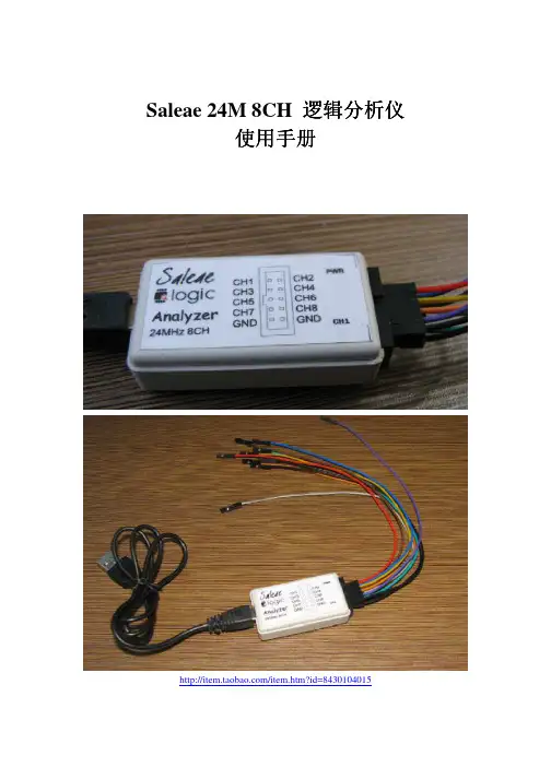
Saleae 24M 8CH 逻辑分析仪使用手册/item.htm?id=8430104015一,软件的安装以及基本使用1,首先安装软件Logic Setup 1.1.4 (32-bit),可从/downloads 下载,还有支持其他操作系统的软件版本,可对应下载。
2,安装完毕之后启动一下我们可以到可以看到以下界面:这个软件在没有接入硬件的时候可以模拟运行,我们可以看到。
点一下START SIMULATION 就可以看到波形,这时候的只是软件根据你设置的要分析的协议(如果你已经设置的话)模拟出来的,随机产生的。
如下图:用鼠标的左键点图形将实现ZOOM IN 放大,右键是ZOOM OUT缩小,如果使用的是三论鼠标,可以使用中键进行放大缩小。
我们也可以移动底部的滑动条来查看波形。
3,安装完毕后插入硬件,出现找到新硬件提示,如下点自动搜索驱动。
之后就能完成驱动加载。
在安装驱动的最后一步,询问你是否从新启动系统,你可以点否,不用重新启动就可以使用。
此时驱动安装完毕。
4,再次启动软件会发现,我们看到现在按钮的名字变成了START 而不是没有接硬件之前的START SIMULATION。
这时候点START将实现8路逻辑信号的采集。
二,关于采样深度和采样率在软件的左上方有两个下拉选项,左边一个是采样深度,右边一个是采样速率。
采样深度就是你总共要采集多少数据,图上的每路都采集25MBIT ;采样速率更好理解,就是一秒采集多少次。
比方说我们采25M标示每路每路集深度是1M采样速率也是1M,那总的采集时间就是1秒。
采集一秒后自动停止采集,并在界面上显示波形。
三,关于波形信息1在软件界面的右上方有波形信息,可以通过点击来选择自己感兴趣的参数。
如下图:2,以下图为例,看一下具体参数都是什么含义:Width :是图中的时间长度.Period :是图中的周期,也就是说将这个电平单独分析,其周期是多少。
而接下来的DUTY Cycle自然就是这个电平作为一个周期来分析,其占空比为多少。

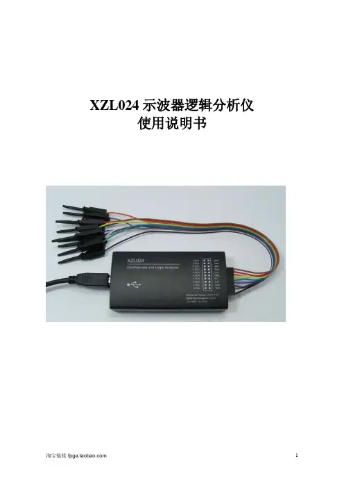
XZL024示波器逻辑分析仪使用说明书1 简介1.1 电脑系统要求1.2 设备清单1.3 硬件参数1.4 软件安装2 示波器2.1 示波器功能参数2.2 快速启动2.3 特性3 逻辑分析仪USBee Suite 3.1 软件安装和注册3.2快速启动3.3 特性3.4 协议分析XZL024示波器逻辑分析仪是一款基于PC的高性价比的电路分析调试工具。
全面兼容和支持“USBee AX Pro”上位机软件。
可以实现示波器,逻辑分析仪等等很多功能。
软件下载地址:USBEE AX Pro: /axsw.zipUSBEE Suite: /usbeesuitesw.zip注意:不正确的使用会造成设备损坏和人员伤害!使用中:●至少保证一条GND线与你的目标板地电位相连;●数字通道DCH1 - 8,TRG和CLK等的电压范围为0-5V;●模拟通道ACH 1和2的电压范围-10到+10V;●XZL024的数字通道可以驱动输出,在使用前一定不要超过电压和电流范围;●先将XZL024连接到PC,再连接需要测试的目标板。
1.1电脑系统要求●Windows XP或者Windows 2000操作系统;●Pentium以上处理器;●USB2.0高速接口,不支持USB1.1全速端口工作;●32MB RAM●125MB 硬盘1.2设备清单●XZL024设备一台;●测试排线夹一条(带10个测试夹)●USB连接线一条;1.3硬件参数由于设备工作在最高的采样速度时,对PC的USB带宽和处理器资源要求较高,因此为了保证稳定工作,●不要在PC上连接其他USB高速设备;●不要在软件采样和输出信号时运行其他的程序。
1.4 软件安装当USBee软件安装过程中,会提示安装Windows的.NET组件,一定要安装.NET组件,否则软件无法正常工作。
先下载在线安装版,开始安装。
当你无法正常在线下载安装时,就要到微软的官网去下载安装Microsoft .Net Framework 3.5 SP1.exe,/downloads/details.aspx?displaylang=zh-cn&FamilyI D=ab99342f-5d1a-413d-8319-81da479ab0d7在页面中下部,下载完整版安装,大小230MB。

目 录1 “启点”逻辑分析仪 (1)1.1 主要功能与基本参数 (1)1.2 信号连接端子分配 (2)1.3 电气特性 (3)1.4 软件操作说明 (3)1.5 硬件操作说明 (3)2 串行通讯分析扩展板 (5)2.1 简介 (5)2.2 接口说明 (5)2.3 跳线说明 (6)2.4 操作说明 (7)1“启点”逻辑分析仪1.1主要功能与基本参数启点逻辑分析仪是一款高性价比的电路逻辑分析工具。
同时支持“USBee AX Pro”和“Saleae Logic”等多种上位机软件,用户可根据自已的喜好选用其中一种软件。
当使用“USBee AX Pro”上位机软件时,启点逻辑分析仪还提供了一个模拟采集通道,可实现一个通道的模拟示波器功能。
1.启点逻辑分析仪支持以下三种软件:推荐使用“USBee Suite”,因为其有更全的串行解码分析工具,更美观的界面,也更易操作。
USBee AX ProUSBee SuiteSaleae Logic2.软件下载地址:下载USBee Suite:/usbeesuitesw.zip下载USBee AX pro:/axsw.zip下载 Saleae Logic:/downloads/logic/Logic%20Setup%20Beta.exe3.启点逻辑分析仪的输入端口有完备的保护:所有输入输出口均能承受±12V输入而不损坏设备。
注意:启点逻辑分析仪使用高速的USB2.0接口,全速工作速度为480Mbps。
因此对USB连接线和USB接口本身的要求要比普通的USB设备要高很多。
而且启点逻辑分析仪无法连接到USB1.1接口。
启点逻辑分析仪工作时需要很高的USB带宽,当您使有USB HUB连接启点逻辑分析仪时,不要在HUB上再连接其它USB设备。
这可能会造成逻辑分析仪无法正常工作。
4.启点逻辑分析仪所支持主流的所有串行解码功能其支持的串行协议主要有:异步串口,标准的UARTSPI接口,四线制IIC总线单总线SMBusPS/2IISCANUSB1.2信号连接端子分配启点逻辑分析仪的信号连接端子使用22Pin的双排端子,其结构和定义如下:上排引脚功能下排引脚功能1 模拟输入2 模拟地3 时钟输出4 触发输入5 数字通道76 数字地7 数字通道6 8 数字地9 数字通道5 10 数字地11 数字通道4 12 数字地13 数字通道3 14 数字地15 数字通道2 16 数字地17 数字通道1 18 数字地19 数字通道0 20 数字地21 外部参考电源22 数字通道方向当用USBee AX Pro软件做为信号发生器时,将22脚数字通道方向接低电平,可连接到20脚即可。
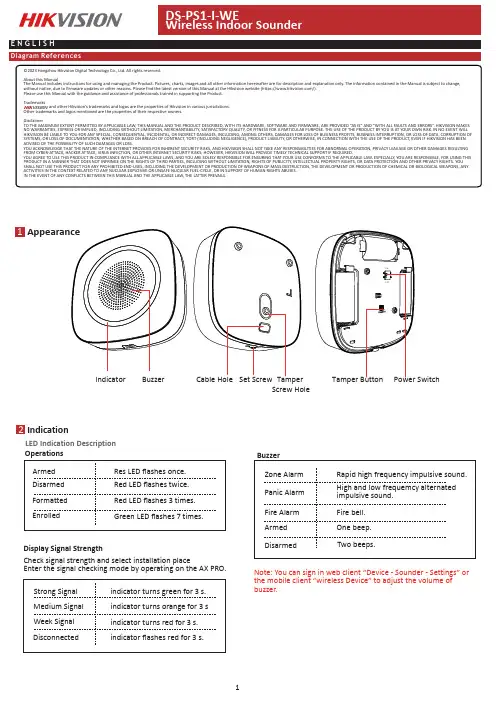
Appearance1Indicator BuzzerCable Hole Set Screw TamperScrewHoleSwitch2IndicationLED Indication Description Buzzer Armed Operations Green LED flashes 7times.EnrolledRed LED flashes 3times.Formatted Red LED flashes twice.Disarmed Res LED flashes once.Display Signal Strengthindicator turns red for 3s.indicator flashes red for 3s.DisconnectedWeek Signal indicator turns orange for 3s Medium Signal indicator turns green for 3s.Strong Signal Check signal strength and select installation placeEnter the signal checking mode by operating on the AX PRO.Zone Alarm Note:You can sign in web client “Device -Sounder -Settings”or the mobile client “wireless Device”to adjust the volume of buzzer.Two beeps.DisarmedOne beep.ArmedFire bell.Fire Alarm High and low frequemcy alternated impulsive sound.Panic Alarm Rapid high frequency impulsive sound.©2023Hangzhou Hikvision Digital Technology Co.,Ltd.All rights reserved.About this ManualThe Manual includes instructions for using and managing the Product.Pictures,charts,images and all other information hereinafter are for description and explanation only.The information contained in the Manual is subject to change,without notice,due to firmware updates or other reasons.Please find the latest version of this Manual at the Hikvision website (https:///).Please use this Manual with the guidance and assistance of professionals trained in supporting the Product.Trademarksand other Hikvision’s trademarks and logos are the properties of Hikvision in various jurisdictions.Other trademarks and logos mentioned are the properties of their respective owners.DisclaimerTO THE MAXIMUM EXTENT PERMITTED BY APPLICABLE LAW,THIS MANUAL AND THE PRODUCT DESCRIBED,WITH ITS HARDWARE,SOFTWARE AND FIRMWARE,ARE PROVIDED “AS IS”AND “WITH ALL FAULTS AND ERRORS”.HIKVISION MAKES NO WARRANTIES,EXPRESS OR IMPLIED,INCLUDING WITHOUT LIMITATION,MERCHANTABILITY ,SATISFACTORY QUALITY ,OR FITNESS FOR A PARTICULAR PURPOSE.THE USE OF THE PRODUCT BY YOU IS AT YOUR OWN RISK.IN NO EVENT WILL HIKVISION BE LIABLE TO YOU FOR ANY SPECIAL,CONSEQUENTIAL,INCIDENTAL,OR INDIRECT DAMAGES,INCLUDING,AMONG OTHERS,DAMAGES FOR LOSS OF BUSINESS PROFITS,BUSINESS INTERRUPTION,OR LOSS OF DATA,CORRUPTION OF SYSTEMS,OR LOSS OF DOCUMENTATION,WHETHER BASED ON BREACH OF CONTRACT,TORT (INCLUDING NEGLIGENCE),PRODUCT LIABILITY ,OR OTHERWISE,IN CONNECTION WITH THE USE OF THE PRODUCT,EVEN IF HIKVISION HAS BEEN ADVISED OF THE POSSIBILITY OF SUCH DAMAGES OR LOSS.YOU ACKNOWLEDGE THAT THE NATURE OF THE INTERNET PROVIDES FOR INHERENT SECURITY RISKS,AND HIKVISION SHALL NOT TAKE ANY RESPONSIBILITIES FOR ABNORMAL OPERATION,PRIVACY LEAKAGE OR OTHER DAMAGES RESULTING FROM CYBER-ATTACK,HACKER ATTACK,VIRUS INFECTION,OR OTHER INTERNET SECURITY RISKS;HOWEVER,HIKVISION WILL PROVIDE TIMELY TECHNICAL SUPPORT IF REQUIRED.YOU AGREE TO USE THIS PRODUCT IN COMPLIANCE WITH ALL APPLICABLE LAWS,AND YOU ARE SOLELY RESPONSIBLE FOR ENSURING THAT YOUR USE CONFORMS TO THE APPLICABLE LAW.ESPECIALLY ,YOU ARE RESPONSIBLE,FOR USING THIS PRODUCT IN A MANNER THAT DOES NOT INFRINGE ON THE RIGHTS OF THIRD PARTIES,INCLUDING WITHOUT LIMITATION,RIGHTS OF PUBLICITY ,INTELLECTUAL PROPERTY RIGHTS,OR DATA PROTECTION AND OTHER PRIVACY RIGHTS.YOU SHALL NOT USE THIS PRODUCT FOR ANY PROHIBITED END-USES,INCLUDING THE DEVELOPMENT OR PRODUCTION OF WEAPONS OF MASS DESTRUCTION,THE DEVELOPMENT OR PRODUCTION OF CHEMICAL OR BIOLOGICAL WEAPONS,ANY ACTIVITIES IN THE CONTEXT RELATED TO ANY NUCLEAR EXPLOSIVE OR UNSAFE NUCLEAR FUEL-CYCLE,OR IN SUPPORT OF HUMAN RIGHTS ABUSES.IN THE EVENT OF ANY CONFLICTS BETWEEN THIS MANUAL AND THE APPLICABLE LAW,THE LATTER PREVAILS.4Enrollment1.Remove the screw on the bottom of the sounder,and disassemble the peripheral and remove the rear panel..2.Insert the batteries.Note:for re-enrollment,you need to hold the tamper button while powering the peripheral on simultaneously.CAUTIONRISK OF EXPLOSION IF BATTERY IS REPLACED BY AN INCORRECT TYPE.DISPOSE OF USED BATTERIES ACCORDING TO THE INSTRUCTIONS CHEMICAL BURNING DANGER DO NOT SWALLOW THE BATTERY KEEP NEW AND USED BATTERIES AWAY FROM THE CHILDRENEnroll the Peripheral LocallyEnroll the Peripheral with APP1.In the APP ,tap the "Enrollment Mode"button on the control panel page to make the control panel enter the enroll-ment status.2.Push the power switch of the peripheral to on,and it will be automatically enrolled to the control panel.1.In the APP ,tap the icon "+"and scan the QR code on the peripheral or enter the serial No.(Last 5digit)of the peripheral.2.Push the power switch of the peripheral to on,and it will be automatically enrolled to the control panel.3.Log in to the APP Store,download and install App.4.Power on the security control panel.5.Log in the APP and tap the icon "+".Scan the QR code or input the control panel serial No.(Last 5digit)to add the control panel.6.Enroll the peripheral locally,with OR code,or with serial No..INSTALL THE BATTERIES ACCORDING TO THE POLARITY MARK ON THE BATTERY HOLDER.THE OPPOSITE POLARITY MAY CAUSE DEVICEDAMAGE52.Loosen the set screw at the bottom of the sounder and remove the front panel.3.Secure the sounder with other three screws.4.Fix the front panel on the sounder body.Tighten the set screw to complete the installation.1.Check signal strength and select tinstallation placeEnter the signal checking mode by operating on the control panel.Signal indicator turns green for 3s:Strong.Signal indicator turns orange for 3s:Medium.Signal indicator turns red for 3s:Weak.Signal indicator flashes red for 3s:Lost.7Operation8Operation Caution and Device MaintenanceSpecification6FormatingHold the tamper button,and push the power switch to ON simultaneously.Release the tamper button after 8s,and the device will strats formating.While the formating is completed,the red LED flashes 3times.-All the electronic operation should be strictly compliance with the electrical safety regulations,fire prevention regula-tions and other related regulations in your local region.-Do not drop the device or subject it to physical shock,and do not expose it to high electromagnetism radiation.Avoid the equipment installation on vibrations surface or places subject to shock (ignorance can cause equipment damage).-Please make sure that the power has been disconnected before you wire,install or dismantle the device.-If smoke,odors or noise rise from the device,turn off the power at once and unplug the power cable,and then please contact the service center.-Do not drop the device or subject it to physical shock,and do not expose it to high electromagnetism radiation.Avoid the equipment installation on vibrations surface or places subject to shock (ignorance can cause equipment damage).-Do not place the device in extremely hot (refer to the specification of the device for the detailed operation tempera-ture),cold,dusty or damp locations,and do not expose it to high electromagnetic radiation.-The device for indoor use shall be kept from rain and moisture.Exposing the equipment to direct sun light,low ventilation or heat source such as heater or radiator is forbidden (igno-rance can cause fire danger).-Do not aim the device at the sun or extra bright places.A blooming or smear may occur otherwise (which is not a malfunction however),and affecting the endurance of sensor at the same time.-Improper use or replacement of the battery may result in hazard of explosion.Replace with the same or equivalent type only.Dispose of used batteries according to the instructions provided by the battery manufacturer.-Do not expose the device to the corrosive gas.Otherwise the equipment damage may occur.-Do not expose the device to the explosive situation.。

逻辑分析仪Usbee-AX-Pro中文说明书————————————————————————————————作者: ————————————————————————————————日期:USBEE AX示波器逻辑分析仪使用说明书1.简介USBEE AX示波器逻辑分析仪是一款基于PC的高性价比的电路分析调试工具。
全面兼容和支持“US Bee AXPro”上位机软件。
可以实现示波器,逻辑分析仪等等很多功能。
注意:不正确的使用会造成设备损坏和人员伤害!使用中:●保证GND线与你的目标板地电位相连;●数字信号地接DGND.数字通道DCH0 - 7,正常测试电压范围为0-8V;●模拟信号地接AGND.模拟通道ACH1 的电压范围-10到+10V;x10是+/-100V;x0.2是+/-2V.●注意ACH1,x10和x0.2不可同时接,比如测5V信号是接AGND和ACH1,x10和x0.2悬空;●数字通道DCH0 -7保护电压(不损坏仪器,但测试结果不正确)最大为10v;●模拟通道保护电压为ACH1:+/-100v;x10:+/-300v;x0.2:+/-10v。
但不要长时间保持。
●D3V3是仪器提供的输出3.3v的接口,可对外提供不超过100mA的电流输出。
●USBEE AX的数字通道可以驱动输出,在使用前一定不要超过电压和电流范围;●先将USBEEAX连接到PC,再运行软件。
电脑系统要求●Windows8.1/7/ XP或者Windows 2000操作系统;●Pentium以上处理器;●USB2.0高速接口,不支持USB1.1全速端口工作;设备清单●USBEE AX设备一台;●测试杜邦线一排10根(可选带测试夹);●USB连接线一条;●光盘(软件和说明文档,也可从商品描述页面提供的链接下载);设备工作在最高的采样速度时,对USB带宽和处理器资源要求较高,为了保证稳定工作: ●不要在PC上连接其他USB高速设备;●最好不要在软件采样和输出信号时运行其他的程序。

逻辑分析仪USBee Suite使用说明书1 软件安装和注册将软件压缩包下载后,解压后安装。
注意:usbee suite支持usbee ax pro 但是不带有硬件驱动. 必须安装好usbee ax的软件并成功安装驱动后,usbee suite 才能正确识别usbee ax .1.1 如果是XP首先运行DOTNETFX35.exe 之后点setup安装USBEE SUITE 软件.1.2 如果是WIN7系统请直接点setup安装USBEE SUITE 软件.1.3 如果安装完usbee suite软件后,运行的时候一闪而过,那是因为没有正确的执行第1点.需要运行notnet35.exe安装一下.从新开启USBEE SUITE 就好.1.4 USBee Suite软件注册后,会增加更多的新功能。
破解的过程,先将设备连接到PC;运行USBee Suite软件,点击菜单项Setup|Register USBee Pro在弹出的窗口中,需要输入注册码;运行破解机软件,在ID框中输入刚才在USBee Suite弹出的窗口中页面中部的数字,点击运算,得到的License Key填入到上一步骤的"Enter Licence Key Here",即可完成注册过程。
2快速启动先将设备连接到PC;将设备的GND与目标板连接;将目标板上的信号连接到DCH 1~8通道上;运行USBee Suite;点击“Capture”按键;查看波形。
3 特性3.1 逻辑分析仪软件设定USBee Suite有快速设定选项,可以方便使用。
快速设定SPI配置前四个通道0,1,2,3为SPI总线的SS,SCK,MOSI和MISO,并且增加了一行SPI解码信息。
快速设定I2C配置通道4,5为I2C总线的SDA和SCL,并且增加了一行I2C解码信息。
快速设定异步通讯配置通道6,7为全双工异步通讯的TX和RX,需要设定好相关的波特率,数据位和校验等参数才能正常使用。
USBEE AX示波器逻辑分析仪使用说明书1. 简介USBEE AX示波器逻辑分析仪是一款基于PC的高性价比的电路分析调试工具。
全面兼容和支持“USBee AX Pro”上位机软件。
可以实现示波器,逻辑分析仪等等很多功能。
注意:不正确的使用会造成设备损坏和人员伤害!使用中:●保证GND线与你的目标板地电位相连;●数字信号地接DGND.数字通道DCH0 - 7,正常测试电压范围为0-8V;●模拟信号地接AGND.模拟通道ACH1 的电压范围-10到+10V;x10是+/-100V; x0.2是+/-2V.●注意ACH1,x10和x0.2不可同时接,比如测5V信号是接AGND和ACH1,x10和x0.2悬空;●数字通道DCH0 - 7保护电压(不损坏仪器,但测试结果不正确)最大为10v;●模拟通道保护电压为ACH1:+/-100v;x10:+/-300v;x0.2:+/-10v。
但不要长时间保持。
●D3V3是仪器提供的输出3.3v的接口,可对外提供不超过100mA的电流输出。
●USBEE AX的数字通道可以驱动输出,在使用前一定不要超过电压和电流范围;●先将USBEE AX连接到PC,再运行软件。
电脑系统要求●Windows 8.1/7/ XP或者Windows 2000操作系统;●Pentium以上处理器;●USB2.0高速接口,不支持USB1.1全速端口工作;设备清单●USBEE AX设备一台;●测试杜邦线一排10根(可选带测试夹);●USB连接线一条;●光盘(软件和说明文档,也可从商品描述页面提供的链接下载);设备工作在最高的采样速度时,对USB带宽和处理器资源要求较高,为了保证稳定工作:●不要在PC上连接其他USB高速设备;●最好不要在软件采样和输出信号时运行其他的程序。
2.安装USBEE AX PRO 的步骤:1. 安装软件前请勿连接硬件。
2.安装USBEE AX PRO 软件。
注意:a)只有在WIN7 64/WIN8 64下才选择安装axsw64BIT_English文件夹。
USBee AX and Saleae软件安装和使用说明USBee AX and Saleae是基于相同的硬件,却使用不同的上位机软件的,Saleae是对逻辑部分进行了强化,采样速率可以达到24M,USBee是多功能的,除了可以做逻辑分析仪用,还可以做信号发生器,频率计,PWM占空比调发生器,或者虚拟示波器等等。
USBee除了可以对应的USBee软件外,所以有USBee 都还可以共用同一个USBee Suite这个软件。
另外USBee Suite这个软件还可以升级为USBee Suite Pro。
Saleae软件的下载地址是:/downloads/请下载最新的软件版本。
USBee所有的软件下载地址是:/download.htm下载时请注意对应自己的操作系统。
另外Saleae Logic和USBee Suite这两个软件都需要.NET Framework 3.5 SP1,所以最好先去Microsoft 官方网上下载一个完整的版本:/downloads/details.aspx?displaylang=zh-cn&FamilyID=ab99342f-5d1a-413d-8319-81da479ab0d7安装好.NET Framework 3.5 SP1,耐心的等待一下,安装需要一点时间。
安装完毕就可以开始下面的流程了。
Saleae Logic安装过程:双击下载的软件按默认方式安装或者自己的选择安装都可以。
安装完Saleae Logic的软件,插上Saleae Logic,电脑会弹出下面对话框:点下一步选仅这一次后:驱动安装完毕:然后可以去设备管理器查看到如下:双击打开Saleae Logic软件,可以看到Connected,已经可以工作了:USBee AX的软件安装过程:双击SETUP.EXE开始安装软件,按默认安装方式即可。
安装完毕,插上USBee AX,电脑会弹出下面对话框:点下一步,或者有的电脑会要选择仅这一次,驱动安装完毕:另外,再安装一下USBee Suite这个软件,USBee AX可以用AX的软件,也可以用USBee Suite这个软件。
AX PRO SolutionIntrusion and Video, refocussed.Designed and produced by the WORLD LEADER in security, it’s time to rethink what your wireless secuirty system can do.Completely driven from your app, on demand, and with a wide range of products, the AX PRO wireless intruder alarm system delivers video on-board, with our revolutionary and proven wireless protocol for knock out stability.HeadquartersNo. 555 Qianmo Road, Binjiang DistrictHangzhou 310052, China T +86 571 88075998F +86 571 89935635******************************AX PRO FAMILYKEY FEATURESThe core building blocks of the AX PRO Solution.It’s all in the appOne manufacturer, one interface. With the AX PRO, the power is in your hands; manage multiple systems through the Hik-ProConnect app and web interface, configure devices, control video and monitor. A totalsystem with total control.Tri-XThe future is now.Fast, reliable and secure, our powerful Tri-X Wireless T echnology delivers the next level of security; speeding up installations, while delivering the best experience for both installers and their customers.Radio silence...Don’t be a victim of jamming or interference! Advanced anti-jamming security on our radio protocol protects theintegrity of the system over the long term, providing increased stability and security.IVaaSOffering a wider view.The AX PRO incorporates IVaaS, integrating videoverification capabilities with 4 camera video buffer ON-BOARD, to show the customer exactly what’s happening, so they can take appropriate action.DesignWe are family!With the AX PRO, the entire range of security, safety and video products deliver the same stylish, professional and uniform finish with equally outstanding performance.Ease of InstallationThe smart installation choice With faster installation and flexibility, over time the panel auto-adapts to changing ISP or equipment; now that’s clever through features like auto-enrollment and quick-install periherals, you can do more.EN G2Be safe in the knowledge your system is fully EN Grade 2 compliant. Building a resilient system tailored to individual needs, without compromising on effectiveness and reliability.Detect with PIRCAMBe secure with detection and video in one! Capturing snapshots as the action happens, stay safe and be informed of an intruder in real time with live updates;keeping you in the loop.DETECTION AND SENSINGA range of detectors and sensors suitable for any residential and small commercial application.The eyes of the operationBattery operated and featuring a 12m range, maintain a secure property and let the wirless PIR-Camera Detector take care of thehard work.Keep on detectingFully programmable via the app and featuring SmartEnvironmental Control (SEC) T echnology, the Wireless PIRDetector really does have it all under control.Compact yet robustUtilising the latest Tri-X Wireless T echnology, the Wireless Magnet Detector is versatile and easily configurable to suit a variety ofneeds. Plus installation has never been easier.Small but mightyEasily installed and featuring smart remote programming the Wireless Slim Magnetic Contact is capable of up to 1600m long distance radio frequency transmission; impressive for something so small.Not to be interfered withThe 24GHz module built into the Wireless Dual-T ech Detector reduces installation time and isn’t afected by interference; nowthat’s smart.Ticking multiple boxesEncompassing multiple uses for superior security, the Wireless PIR-Glass Break Detector does just that. With a 12m detection range and built in break-glass technology, you’re completely sorted.Be heard when you need itOffering a compact design for maximum installation flexibility; delivering an inconspicuous finish that blends in with any property. Don’t worry, it’ll let you know that it’s there!Freedom with securityPortable and discreet, raise an alarm with minimal fuss and straight-forward set up of the Wireless Portable Emergency Button.Protect those that matter mostDiscreet but functional with an IP54 rating, stay protected against danger and water exposure. Providing peace of mind when it’sneeded most.All eyes and ears on meAvailable in red or blue and designed for easy installation, the Wireless External Sounder offeres up to 110db alarm volume; be alerted when it matters most.Discreet has never been so loud!Raise an alarm with the Wireless Emergency Button. Fully remote configurable, frequency hopping technology for improved signal transmission and easy installation; a no-brainer for any security needs.Control your home in one placeArming made easy. Control a property and be made aware of any faults with the touch LED display. Giving you the freedom to be in charge of the system.Ready, set, GO!Small and compact, yet fully customisable and robust, the keyfob is the perfect arming/disarming partner. Featuring an LED display for instant feedback on setting functions, trust that the system is ready for action.Stable, secure and straightforward armingBuilt with modern design and flexibility in mind; arm or disarm the entire system or just separate areas. Providing a stylish T ag Reader with control where it’s needed most.Various arming and control options to suit.ARMING AND CONTROLA range of sounders and panic buttons, raising the alarm.SOUND AND ALERTWireless PIR-Glass BreakDetector Wireless PIR-Camera Detector Wireless Magnet Detector Wireless Slim MagnetDetectorWireless Internal Sounder Wireless LED KeypadWireless RepeaterPRODUCTS AND PARTCODESDS-PDD12P-EG2-WE Wireless Dual-T ech Detector SAP Code: 314300071DS-PDMCS-EG2-WEWireless Slim Magnet ContactSAP Code: 314300061DS-PDBG8-EG2-WEWireless Glass Break DetectorDS-PS1-I-WEWireless Internal Sounder SAP Code: 302401660 (red)302401666 (blue)DS-PK1-E-WE Wireless LED Keypad SAP Code: 302401663DS-PKF1-WE KeyfobSAP Code: 302401661DS-PT1-WEOM I N G S O O N DS-PDEB2-EG2-WE Wireless Emergency Button SAP Code: 314300063DS-PDEBP2-EG2-WE Wireless Emergency Button(portable)SAP Code: 314300057DS-PDSMK-S-WE Wireless Smoke Detector DS-PSP1-WE Smart SocketO M I N G S O O N O M I N G S O O N N G S O O N M I N G S O O N N M I N G S O O N C OM I N G S O O N C OM I N G S O O N。
輕鬆自如地運用邏輯分析儀應用手冊1337目錄前言35512172023示波器或邏輯分析儀什麼是邏輯分析儀時序分析儀的基本概念狀態分析儀的基本概念有效率地使用數位工具如何連接到標的系統結語用對工具可以幫助您在較短的時間內順利克服數位除錯挑戰,而在挑選適合的工具之前,務必先瞭解您可以使用的工具有哪些,以及它們最擅長的應用。
本應用手冊會帶您快速綜覽邏輯分析儀的基本概念,文中不會提到太多詳細的量測,但會清楚敘述邏輯分析儀的功用。
我們會探討諸如“為何必須使用邏輯分析儀?”及“邏輯分析儀可以幫我做些什麼?”之類的問題。
/find/logic 2? ?示波器或邏輯分析儀? 當有機會可以選擇使用示波器或邏輯分析儀時,許多工程人員都會選擇示波器,這是因為大多數的使用者都對示波器比較熟悉,但示波器在某些應用上會有一些限制。
依您想完成的作業而定,邏輯分析儀所產生的資訊可能更為有用。
由於示波器與邏輯分析儀有部分功能是重複的,因此在某些情況下兩者皆適用。
該如何決定哪一種儀器對您的應用更有利?讓我們看看幾個基本的原則。
何時應使用示波器當您要查看信號的細微電壓變化時當您要求較高的時間間隔準確度時 一般來說,當您需要較高的垂直或電壓解析度時,選用示波器就對了。
換言之,如果您要查看每個電壓的總改變值,如圖1所示,則應使用示波器。
包括新一代數位示波器在內的許多示波器,也能提供相當高的時間間隔解析度,亦即它們可以非常準確地量測兩個事件間的時間間隔。
總之,當您需要參數資訊時,請使用示波器。
圖1.示波器波形3何時應使用邏輯分析儀當您必須一次查看許多信號時當您必須如硬體一般來查看系統中的信號時當您必須在幾個高、低位準信號的碼型上觸發及查看結果時 邏輯分析儀是由示波器衍生而來,並以相同於示波器的一般方式來呈現資料:水平軸為時間,垂直軸為電壓振幅。
雖不像示波器能提供較高的電壓解析度或時間間隔準確度,但邏輯分析儀一次擷取及顯示幾百個信號的能力卻是示波器所不及的。
逻辑分析仪入门手册RD/EE孟俊贤2009-2-20目录1 逻辑分析仪入门...................................................................................................- 3 -1.1逻辑分析基础知识....................................................................................- 3 -1.2 什么是逻辑分析仪?...............................................................................- 3 -2 定时分析仪...........................................................................................................-3 -2.1定时分析仪中的基本功能........................................................................- 3 -2.1.1定时分析仪中的采样时钟............................................................- 4 -2.1.2定时采集模式下的采样................................................................- 4 -2.1.3采样精度........................................................................................- 4 -2.2触发定时分析仪........................................................................................- 5 -2.2.1码型触发........................................................................................- 5 -2.2.2时钟沿触发....................................................................................- 5 -3 状态分析仪...........................................................................................................- 6 -3.1状态分析仪中的基本功能........................................................................- 6 -3.1.1状态分析仪中的采样时钟............................................................- 6 -3.1.2状态采集模式下的采样................................................................- 6 -3.2触发状态分析仪........................................................................................- 6 -4 图形界面...............................................................................................................- 6 -4.1打开逻辑分析仪........................................................................................- 6 -4.2 前面板操作...............................................................................................- 7 -Run/Stop(运行/停止)按钮.................................................................- 7 -通用旋钮...................................................................................................- 7 -4.3 软件操作界面...........................................................................................- 8 -5 被测设备连接.......................................................................................................- 8 -5.1探测被测设备连接方法............................................................................- 9 -6 测量概述...............................................................................................................- 9 -6.1 设置总线/信号名称.................................................................................- 9 -6.1.1删除总线/信号名称......................................................................- 9 -6.1.2添加新的总线/信号名称............................................................- 10 -6.2 将信号映射到分析仪中.........................................................................- 10 -6.3 设置采集模式.........................................................................................- 11 -6.4 设置简单触发.........................................................................................- 11 -6.5数据分析..................................................................................................- 12 -6.5.1查看数据......................................................................................- 12 -6.7使用标记..................................................................................................- 12 -6.7.1创建标记......................................................................................- 12 -6.7.2 在数据中放置标记.....................................................................- 13 -6.7.3转至数据中的标记......................................................................- 13 -6.7.4放大数据......................................................................................- 13 -7 展开总线.............................................................................................................- 13 -7.1展开总线..................................................................................................- 14 -7.2更改刻度..................................................................................................- 14 -1 逻辑分析仪入门1.1逻辑分析基础知识一般而言,逻辑分析仪用于查看多个信号之间的定时关系,或者当您需要在出现逻辑上限和下限码型时触发的情况下使用。
声明: 本文来自分析仪开发手册.pdf)前言一、什么是逻辑分析仪二、使用介绍三、安装说明四、Saleae软件使用方法五、逻辑分析仪硬件安装六、使用Saleae分析电视红外遥控器通信协议七、使用Saleae分析UART通信八、使用Saleae分析IIC总线通信九、使用Saleae分析SPI总线通信十、Saleae逻辑分析仪使用问题和注意事项淘宝地址:(原文件名:21.jpg)前言:工欲善其事,必先利其器。
逻辑分析仪是电子行业不可或缺的工具。
但是由于一直以来,逻辑分析仪都属于高端产品,所以价格居高不下。
因此我们首先要感谢Cypress公司,提供给我们68013这么好的芯片,感谢俄罗斯毛子哥将这个Saleae逻辑分析仪开源出来,让我们用平民的价格,就可以得到贵族的待遇,获得一款性价比如此之高的逻辑分析仪,可以让我们在进行数字逻辑分析仪的时候,快速查找并且解决许多信号、时序等问题,进一步提高我们处理实际问题的能力。
原本计划,直接将Saleae的英文版本使用手册直接翻译过来提供给大家,我花费半天时间翻译完后,发现外国人写的东西不太符合我们国人的思维习惯,当然,也是由于我的英语水平有限,因此,我根据自己摸索这个Saleae的过程,写了一份个人认为符合中国人习惯的Saleae,提供给大家,希望大家在使用过程中少走弯路,快速掌握使用方法,更快的解决自己实际遇到的问题。
由于个人水平有限,因此在文章撰写的过程中难免存在问题和错误,如果有任何问题,希望大家能够提出来,我会虚心接受并且改进,希望通过我们的交流,给越来越多的人提供更加优秀的资料,共同进步。
一、什么是逻辑分析仪:逻辑分析仪是一种类似于示波器的波形测试设备,它通过采集指定的信号,并通过图形或者数据统计化的方式展示给开发人员,开发人员通过这些图形化时序信号按照协议来分析硬件或者软件中的错误。
逻辑分析仪是设计中不可缺少的设备,通过它,可以迅速定位错误,发现并解决问题,达到事半功倍的效果,尤其在分析时序,比如1wire、I2C、UART、SPI、CAN等数据的时候,应用逻辑分析仪解决问题非常快速。
逻辑分析仪UsbeeAXPro中文说
明书
USBEE AX示波器逻辑分析仪
使用说明书
1. 简介
USBEE AX示波器逻辑分析仪是一款基于PC的高性价比的电路分析调试工具。
全面兼容和支持“USBee AX Pro”上位机软件。
能够实现示波器,逻辑分析仪等等很多功能。
注意:不正确的使用会造成设备损坏和人员伤害!使用中:
●保证GND线与你的目标板地电位相连;
●数字信号地接DGND.数字通道DCH0 - 7,正常测试电压范围为0-8V;
●模拟信号地接AGND.模拟通道ACH1 的电压范围-10到+10V;x10是
+/-100V; x0.2是+/-2V.
●注意ACH1,x10和x0.2不可同时接,比如测5V信号是接AGND和
ACH1,x10和x0.2悬空;
●数字通道DCH0 - 7保护电压(不损坏仪器,但测试结果不正确)最大
为10v;
●模拟通道保护电压为ACH1:+/-100v;x10:+/-300v;x0.2:+/-10v。
但不要长时间保持。
●D3V3是仪器提供的输出3.3v的接口,可对外提供不超过100mA的电
流输出。
●USBEE AX的数字通道能够驱动输出,在使用前一定不要超过电压和电
流范围;
●先将USBEE AX连接到PC,再运行软件。
电脑系统要求
●Windows 8.1/7/ XP或者Windows 操作系统;
●Pentium以上处理器;
●USB2.0高速接口,不支持USB1.1全速端口工作;
设备清单
●USBEE AX设备一台;
●测试杜邦线一排10根(可选带测试夹);
●USB连接线一条;
●光盘(软件和说明文档,也可从商品描述页面提供的链接下载);
设备工作在最高的采样速度时,对USB带宽和处理器资源要求较高,为了保证稳定工作:
●不要在PC上连接其它USB高速设备;
●最好不要在软件采样和输出信号时运行其它的程序。
2.安装USBEE AX PRO 的步骤:
1. 安装软件前请勿连接硬件。
2.安装USBEE AX PRO 软件。
注意:
a)只有在WIN7 64/WIN8 64下才选择安装axsw64BIT_English文件夹。
其余选择32位版本。
b)必须使用默认路径。
c)如果要安装中文版必须先安装好英文版后才能安装中文版。
不论是32位还是64位,中文版都是安装同一个中文版升级包exe
3. 接入USBEE AX PRO,如果弹出找到新硬件,点自动搜索驱动,等待安装驱动完毕。
4. 软件安装完成后插入硬件后,可查看设备管理器里有下面红圈图标:
5.当USBee软件安装过程中,如果提示安装Windows的.NET组件,一定要安装.NET组件,否则软件无法正常工作。
先下载在线安装版,开始安装。
当你无法正常在线下载安装时,就要到微软的官网去下载安装Microsoft .Net Framework 3.5 SP1.exe,,在页面中下部,下载完整版安装,大小230MB。
3. 运行软件快速指南
1.要先接入硬件后,再运行软件,才能正常连接。
如果软件界面已经打
开,再连接USB,软件是不能识别到硬件的。
2.安装完后(AXpro中文版),开始菜单有下列程序:
3.一般以AX示波器,AX逻辑分析仪,AX混合信号示波器较常见。
注意
各子软件不能同时使用。
已经有软件运行,要使用另一软件,要关闭已打开的软件。
4.下面对上述3种软件做一下简单介绍:
A)AX示波器。
先连接好示波器到电脑的USB,示波器电源灯亮后,点击开始菜单里的AX示波器软件。
示波器硬件盒子的另一个LED灯PWR 会亮。
示波器接杜邦线的端口,AGND和ACH1分别接待测信号的地和信号。
软件界面的“已触发”小图标会一闪一闪。
注意要调节好时间和电压。
一般1Khz5V信号可秒/格调为500us,伏/格调节为2V。
波形会连续显示。