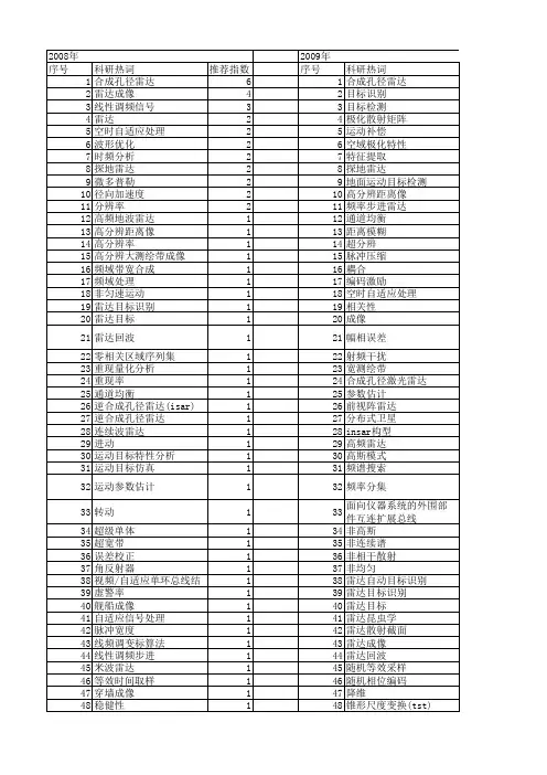
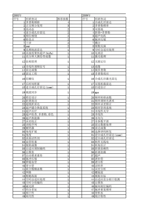
SAR雷达目标信号模拟器案例
- 格式:doc
- 大小:52.00 KB
- 文档页数:2

风电场毫米波雷达技术研究及应用摘要:现阶段,“碳达峰,碳中和”发展战略的执行效果越发显著,再加上电力体制的改革工作持续深入,对我国风电行业的发展具有良好的推动作用。
本文以上述内容为基础,针对风电场毫米波雷达技术展开研究,分析毫米波雷达技术的关键作用,整理相关经验,给出针对性发展建议,希望能够为同领域工作者提供合理参考作用。
关键词:风电场;毫米波雷达技术;新能源开发与应用前言:风能作为重要的可再生清洁能源之一,在现代化电力系统中承载着越来越重要的电力支持任务。
其中,风场信息测量工作作为风电行业保持良好发展状态的重要内容,属于风电场内不可或缺的重要组成结构。
在风力发电机工作并获取风能的过程中,为进一步提升电能的实际生产效率,需借助传感技术,主动感知风速、风向信息,并辅助完成风机控制任务,及时校正偏航误差问题,通过这种方式准确控制风机的最终指向,达到提升发电总量的效果。
一、米波雷达测风基本原理常规情况下,风资源评估、风功率预测系统、风电场运营管理等内容均属于风力发电系统中的重要内容,因此,需要对300m范围内的所有风速风向信息进行全面探测[1]。
在传统类型的风场中,测风塔作为主要测量工具,发挥着重要作用,但是,因其建设成本相对较高,并且灵活度不足,在风场测量工作中存在较多不便,所以,需要找出一种更加便捷且准确的探测技术,完成测风任务。
基于此,以激光和声波技术为主的测风雷达设备在风力发电行业中的应用正变得越发广泛,但是,在实际使用过程中,同样存在一些问题会对探测效果造成影响,需要得到妥善处理。
本文以上述内容为背景,对现有新型测风技术及其产品进行详细说明,即毫米波测风雷达设备,该设备不仅可以在不同高度内准确测得风力信息,同时还可以保证自身在各种不良环境下保持稳定工作状态,保证最终测得数据的准确性。
在此期间,在实际使用的过程中还具有天候、雨天性能好、无噪声、低功耗等诸多使用优势,可以为相关企业和技术人员提供更为优质的辅助效果。
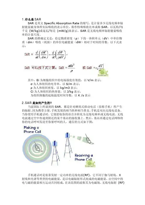
1.什么是SARSAR是英文Specific Absorption Rate的缩写,是计量多少无线电频率辐射能量被身体所实际吸收的表示单位,称作特殊吸收比率或称SAR,以瓦特/每千克 (W/kg)或毫瓦/每克 (mW/g)来表示。
SAR是无线电频率辐射能量吸收率的计量尺度。
SAR的准确定义是:给定物质密度(ρ)下的一体积单元(dV)中单位物质(dm)吸收(耗损)的单位电磁能量(dW)相对于时间的导数,以下式表示:其中:Ei为细胞组织中的电场强度有效值,以V/m表示;σ为人体组织的电导率,以S/m表示;ρ为人体组织密度,以kg/m3表示;Ci为人体组织的热容量,以J/kg表示,为组织细胞的起始温度时间导数,以K /s表示2.SAR是如何产生的?当前国际上所谈到的SAR,都是针对蜂窝式移动电话(俗称手机)所产生的辐射。
因为携带方便,手机发展的相当快和相当普及。
手机是双向无线电设备。
当你使用手机通话时,它便拾取你的语音并转化为无线电频率或无线电波。
无线电波通过空中传递到附近的某个基站的接收器上。
然后,基站再通过电话网络将你的电话呼叫发送至你要呼叫的人。
通信的方式如下图:手机通话时是依靠发射一定功率的无线电波(RF),它不同于伽马射线、X射线和光谱等类型的电磁能量,是以电磁辐射形式组成的电磁能量,由空间中的电与磁的能量相互运动共同组成,在该范围的波称其为电磁场。
无线电辐射 (RF)能量的用途广泛,电信、无线电收音机、电视广播、无线电话、寻呼机、非接触卡电话、警察和消防部门的无线电工具)、点对点联络和卫星通讯均依赖于无线电频率辐射(RF)能量。
另外的用途还包括微波炉、雷达、工业加热器、熨斗、医疗设施等。
微波频率段的无线电(RF)能量能够热水,能够快速烹调含水量大的食品;雷达依赖于无线电 (RF)跟踪汽车和飞机,并用于军事用途;工业炉和熨斗使用无线电 (RF)能量加工成形可塑材料、胶木制品、密封皮革如鞋和皮夹、加工食品;无线电 (RF)能量的医疗用途包括起搏器的监控和操作。
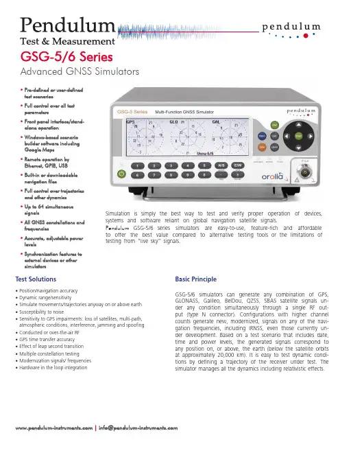
Basic PrincipleG SG -5/6 simulators can generate any combination of G PS, G LONASS, G alileo, BeiDou, QZSS, SBAS satellite signals un-der any condition simultaneously through a single RF out-put (type N connector). Configurations with higher channel counts generate new, modernized, signals on any of the navi-gation frequencies, including IRNSS, even those currently un-der development. Based on a test scenario that includes date, time and power levels, the generated signals correspond to any position on, or above, the earth (below the satellite orbits at approximately 20,000 km). It is easy to test dynamic condi-tions by defining a trajectory of the receiver under test. The simulator manages all the dynamics including relativistic effects.Test Solutions•Position/navigation accuracy •Dynamic range/sensitivity•Simulate movements/trajectories anyway on or above earth •Susceptibility to noise•Sensitivity to GPS impairments: loss of satellites, multi-path, atmospheric conditions, interference, jamming and spoofing •Conducted or over-the-air RF •GPS time transfer accuracy •Effect of leap second transition •Multiple constellation testing•Modernization signals/ frequencies •Hardware in the loop integrationGSG-5/6 SeriesAdvanced GNSS Simulators•Pre-defined or user-defined test scenarios•Full control over all test parameters•Front panel interface/stand-alone operation•Windows-based scenario builder software including Google Maps •Remote operation by Ethernet, GPIB, USB •Built-in or downloadable navigation files•Full control over trajectories and other dynamics •Up to 64 simultaneous signals•All GNSS constellations and frequencies•Accurate, adjustable power levels•Synchronization features to external devices or other simulatorsSimulation is simply the best way to test and verify proper operation of devices, systems and software reliant on global navigation satellite signals.Pendulum G SG -5/6 series simulators are easy-to-use, feature-rich and affordable to offer the best value compared to alternative testing tools or the limitations of testing from “live sky” signals. | *****************************•Constellations: GPS, GLONASS, Galileo, BeiDou, QZSS, IRNSS •Modulations: BPSK, QPSK, BOC (all)•SBAS: WAAS, EGNOS, GAGAN, MSAS, SAIF (included)•Spurious transmission: ≤40 dBc •Harmonics: ≤40 dBc•Output signal level: -65 to -160 dBm; 0.1 dB resolution down to -150 dBm; 0.3 dB down to -160 dBm•Power accuracy: ±1.0 dB •Pseudorange accuracy: Within any one frequency band:1 mm; Across different frequency bands: 30 cm•Inter-channel bias: Zero•Inter-channel range: >54 dB •Limits:Standard ExtendedAltitude18,240 m(60,000 feet)20,200,000 m (66,273,000 feet)Acceleration 4.0 g No limitsVelocity515 m/s (1000knots)20,000 m/s (38,874 knots)Jerk20 m/s3No limit •White noise signal level: -50 to -160 dBm; 0.1 dB resolution down to -150 dBm;0.3 dB down to -160 dBm. ±1.0 dB accuracy External Frequency Reference Input •Connector: BNC female•Frequency: 10 MHz nominal•Input signal level: 0.1 to 5Vrms•Input impedance: >1kΩFrequency Reference Output •Connector: BNC female•Frequency: 10 MHz sine•Output signal level: 1Vrms in to 50 Ω load External Trigger Input•Connector: BNC female•Level: TTL level, 1.4V nominalXPPS Output•Connector: BNC female•Rate: 1, 10, 100, 1000 PPS (configurable)•Pulse ratio: 1/10 (1 high, 9 low)•Output signal level: approx. 0V to +2.0V in 50 Ω load•Accuracy: Calibrated to ±10 nSec of RF timing mark output (option to reduce by a factor of ten with a characterization of offsets)Built-in TimebaseInternal Timebase – High Stability OCXO •Ageing per 24 h: <5x10⁻¹⁰•Ageing per year: <5x10⁻⁸•Temp. variation 0…50°C: <5x10⁻⁹•Short term stability (Adev @1s): <5x10-12 Auxiliary FunctionsInterface•GPIB (IEEE-488.2), USB 1.X or 2.X (SBTMC-488), Ethernet (100/10 Mbps)Settings•Predefined scenarios: User can change date, time, position, trajectory, number of satellites, satellite power level and atmospheric model •User defined scenarios: Unlimited •Trajectory data: NMEA format (GGA or RMC messages, or both), convert from other formats with GSG StudioView™ (see separate datasheet)General SpecificationsCertifications•Safety: Designed and tested for Measurement Category I, Pollution Degree 2, in accordance with EN/IEC 61010-1:2001 and CAN/CSA-C22.2 No. 61010-1-04 (incl. approval)•EMC: EN 61326-1:2006, increased test levels per EN 61000-6-3:2001 and EN 61000-6-2:2005 Dimensions•WxHxD: 210 x 90 x 395 mm(8.25” x 3.6” x 15.6”)•Weight: approx. 2.7 kg (approx. 5.8 lb) Optional Antenna•Frequency: 1000 to 2600 MHz •Impedance: 50 Ω•VSWR: <2:1 (typ)•Connector: SMA male•Dimensions: 15 mm diameter x 36 mm length Environmental•Class: MIL-PRF-28800F, Class 3•T emperature: 0°C to +50°C (operating); -40°C to +70°C non-condensing @ <12,000 m (storage)Humidity:•5-95 % @ 10 to 30°C•5-75 % @ 30 to 40°C•5-45 % @ 40 to 50°CPower•Line Voltage: 100-240 V AC, 50/60/400 Hz •Power Consumption: 40 W max.Simple Set-up and Operation Even the most inexperienced operator can configure scenarios on-the-fly without the need for an external PC and pre-compila-tion phase. Via the front panel, the user can swiftly modify parameters. Each unit comes with a license for GSG StudioView™ Windows software to graphically create, modify, and upload scenarios. A G oogle Maps interface makes trajectory creation easy. Trajectories can also be defined by recorded or generated NMEA formats. Connectivity Extends Ease-of-use and FlexibilityG SG simulators can be controlled via an Ethernet network connection, USB or GPIB. A built-in web interface allows complete operation of the instrument through front panel controls. It also al-lows for file transfers. Connectivity also supports the integration of G NSS simula-tion into a wide range of other applica-tions. There is an option to control signal generation in real-time through a simple command set. It can synchronize to ex-ternal systems in many other ways based on its precision timing capabilities and the ability to automatically download ephem-eris and almanac data via RINEX files. Input/OutputRF GNSS Signal Generation •Connector: Type N female•DC blocking: internal, up to 7 VDC; 470 Ωnominal load•Frequency bands:•L1/E1/B1/SAR: 1539 to 1627 MHz•L2/L2C: 1192 to 1280 MHz•L5/E5/B2: 1148 to 1236 MHz•E6/B3:1224 to 1312 MHz•Output channels:•1 (GSG-51); 4, 8, 16 (GSG-5); 32 (GSG-62),48, (GSG-63), 64 (GSG-64)•Any channel can generate anyconstellation or a derivative signal(multipath, interference, jamming)•Any set of 16 channels can generate withina frequency bandOptional FeaturesRecord and Playback (OPT-RP)This option provides the easiest way to create a complex scenario by recording satellite signals on a route. This option includes a recording receiver and software to automatically generate a simulation scenario that can be modified to ask ‘what if’ questions.•True life constellation replication •Automatic scenario generation•Ability to modify signal parameters •Compatible with any recording that includes NMEA 0183 RMC, GGA, and GSV sentences Real-time Scenario Generator (OPT-RSG) This option supports generation of 6DOF trajectory information via position, velocity, acceleration, or heading commands as the input for GPS RF generation. Vehicle attitude and attitude rate changes, as well as satellite power levels, are also controllable via real-time commands.•Control trajectories using 6DOF•Low fixed latency from command input to RF output•Hardware-in-the-loop applications •Includes sensor simulation optionRTK/DGNSS Virtual Reference Station (OPT-RTK)This option supports generation of RTCM correction data messages for testing an RTK / Differential-GNSS receiver.•Generates RTCM 3.x correction data via 1002, 1004, 1006, 1010, 1012, and 1033 messages•User settable base station location •Support for GNSS RTK receivers using serial interfacesHigh Velocity Option (OPT-HV)This option extends the limits for simulated trajectories. As of August 2014, the extended limits are no longer USA export controlled. (See Limits chart under Input/Output specifications.) Jamming Simulation (OPT-JAM)This option extends the capability of the standard interference simulation feature. Set noise or sweep types of interference and create a location-based jammer to test your system’s susceptibility.•Adjustable bandwidth and amplitude interference•Location-based jamming•Swept-frequency jammingeCall Scenarios (OPT-ECL)This option provides scenarios for testing eCall in vehicle systems per Regulation (EU) 2017/79.Sensor Simulation (OPT-SEN)This option generates sensor data in responseto a query according to the trajectory of theGPS RF simulation in real-time. See technicalnote for more details.•Simultaneously test GPS plus other sensorinputs to your nav system•Simulate data for accelerometers,gravimeters, gyroscopes and odometersOrdering InformationBase Configurations•GSG-51: Single channel GPS L1 generator(contact the factory for alternativeconstellations and upgrades to multi-channeland/or frequencies)•GSG-5: 4-channel GPS L1 simulator.Software options increase output channelsto 8 or 16, and adds GLONASS, BeiDou (B1),Galileo (E1), or QZSS constellations. Factoryupgradable to GSG-62 to add more channeland/or frequencies)•GSG-62: 32-channels and up to 2simultaneous frequency bands. Softwareoptions adds GLONASS, BeiDou, Galileo,QZSS or IRNSS constellations; and addssignals on other frequencies (P-code, L2,L2C, Galileo E5a/b, BeiDou B2)•GSG-63: 48-channels and up to 3simultaneous frequency bands. Samesoftware options as GSG-62•GSG-64: 64-channels and up to 4simultaneous frequency bands. Samesoftware options as GSG-62Included with instrument•User manual and GSG StudioView software(one license per unit) on CD•RF cable, 1.5 m•SMA to Type N adapter•USB cable•Certificate of calibration•3-year warranty1Optional Accessories•Option 01/71: Passive GNSS Antenna•Option 22/90: Rack-mount kit•Option 27H: Heavy-duty hard transport case•OM-54: User Manual (printed)•Additional StudioView licenses are availableOptional UpgradesConstellations•OPT-GLO: GLONASS Constellation•OPT-GAL: Galileo Constellation•OPT-BDS: BeiDou Constellation•OPT-QZ: QZSS Constellation•OPT-IRN: IRNSS Constellation (requires atleast GSG-62 and OPT-L5)Frequencies (requires at least GSG-62; non-GPS signals are enabled when constellationoption is installed)•Option L2: enables GPS L1P, GPS L2P, GLOL2 C/A•Option L2C: enables GPS L2C•Option L5: enables GPS L5, Galileo E5 a/b,BeiDou B2, IRNSS L5•Option L6: enables Galileo E6 b/cChannels/Simultaneous Frequencies2•Option 8: 4-channel to 8-channel upgrade•Option 16: 8-channel to 16-channel upgrade•Option 32/2: 16-channel to 32-channel, dualfrequency upgrade•Option 48/3: 32-channel to 48-channel, threefrequency upgrade•Option 64/4: 48-channel to 64-channel, fourfrequency upgradeApplication Packages (typical requirement for16 channel min)•OPT-RSG: Real-time scenario generator•OPT-HV: High velocity upgrade to extendedlimits•OPT-RP: Record and playback package•OPT-JAM: Jamming package•OPT-RTK: RTK virtual base station scenarios•OPT-SEN: Sensor simulation data via protocol(included with OPT RSG)•OPT-ECL: eCall scenariosOptional Services•Option 90/54:GSG Calibration Service•Option 95/05: Extended warranty to 5 years•GSG-INST: User Training and Installation•OPT-TIM: Timing Calibration Service1Warranty period and available services may vary dependent on country.2Option may require the unit to be returned to factory for upgrade.Models Channels # of Sim.Freq.Upgrade to nexthigher modelUpgradetypeConstellations and Signal T ypes Frequency BandsGSG-5111OPT-4Software GPS L1 C/A IncludedOthers if constellation is ordered:•GLONASS L1 C/A •QZSS L1•Galileo E1•BeiDou B11539-1627 MHz (L1)GSG-541OPT-8Software 8OPT-16Software 16OPT-32/2FactoryGSG-62322OPT-48/3Factory Same as aboveOptions if constellation andfrequency are ordered:•GPS L1P, L2P, GLONASS L2 C/A (OPT L2)•GPS L2C (OPT L2C)•GPS L5, IRNSS L5, Galileo E5a/b,BeiDou B2 (OPT L5)Same as above and 3 other ranges•1192-1280 MHz (L2)•1148-1236 MHz (L5)•1224-1312 MHz (E6/B3)GSG-63483OPT 64/4FactoryGSG-64644––Configuration SummaryOct 29, 2018 rev.2© 2018, Pendulum Instruments and OroliaSpecifications subject to change or improvement without notice.。
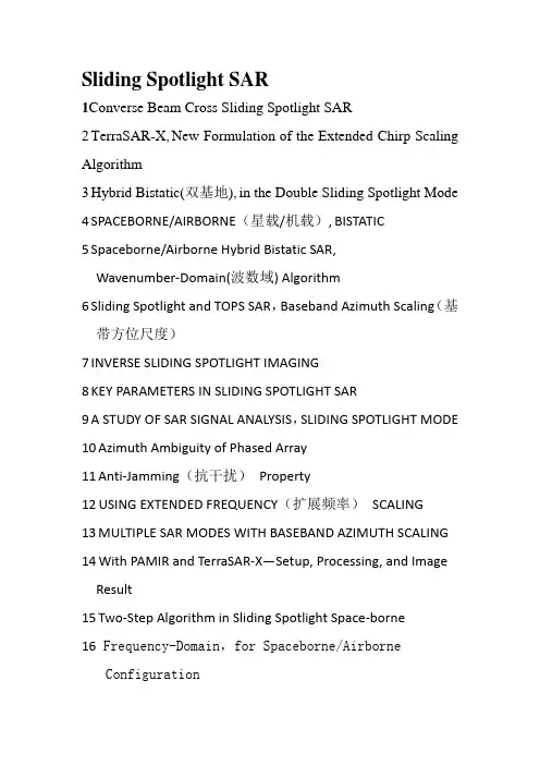
Sliding Spotlight SAR1Converse Beam Cross Sliding Spotlight SAR2TerraSAR-X,New Formulation of the Extended Chirp Scaling Algorithm3Hybrid Bistatic(双基地),in the Double Sliding Spotlight Mode 4SPACEBORNE/AIRBORNE(星载/机载),BISTATIC5Spaceborne/Airborne Hybrid Bistatic SAR,Wavenumber-Domain(波数域) Algorithm6Sliding Spotlight and TOPS SAR,Baseband Azimuth Scaling(基带方位尺度)7INVERSE SLIDING SPOTLIGHT IMAGING8KEY PARAMETERS IN SLIDING SPOTLIGHT SAR9A STUDY OF SAR SIGNAL ANALYSIS,SLIDING SPOTLIGHT MODE 10Azimuth Ambiguity of Phased Array11Anti-Jamming(抗干扰)Property12USING EXTENDED FREQUENCY(扩展频率)SCALING13MULTIPLE SAR MODES WITH BASEBAND AZIMUTH SCALING 14With PAMIR and TerraSAR-X—Setup, Processing, and Image Result15Two-Step Algorithm in Sliding Spotlight Space-borne16 Frequency-Domain,for Spaceborne/AirborneConfiguration17 KOMPSAT-5 SPOTLIGHT SAR PROCESSOR, USING FSA WITH CALCULATION OF EFFECTIVE VELOCITY18 Time-Frequency,High-Resolution19 A Special Point Target Reference Spectrum20 Hybrid(混合式) Bistatic SAR TerraPAMIR,Geometric Description and Point Target Simulation(几何描述与点目标仿真)21Using Azimuth Frequency De-ramping(方位频率去斜)22Sliding Spotlight,TOPS SAR Data,Without Subaperture (子孔径)23 EXTENDED THREE-STEP FOCUSING ALGORITHM24The Study of realization method(实现方法)25Double Sliding Spotlight Mode with TerraSAR-X and PAMIR Based on Azimuth Chirp Filtering26A Unified(统一的) Focusing Algorithm(UFA),Based on FrFT(fractional(分数) Fourier transform)27 A MULTI-MODE SPACE-BORNE,BASED ON SBRAS(Space-borne Radar Advance Simulator)(星载雷达超前模拟器)28PRESENCE OF SQUINT(下斜视)29Large-Scene,Multiple Channels in Azimuth30Full-Aperture Azimuth,for Beam Steering (光束控制)SAR31Beam Steering (光束控制)SAR Data Processing by a Generalized PFA32Multichannel,Ultrahigh-Resolution(超高分辨率) and Wide-Swath Imaging(宽测绘带成像)33A Multi-mode Space-borne SAR34Processing of Ultrahigh-Resolution Space-borne Sliding Spotlight SAR Data on Curved Orbit(曲线轨迹)35Multichannel Sliding Spotlight and TOPS Synthetic Aperture Radar Data36Burst Mode Synthetic Aperture Radar(突发模式合成孔径雷达)37Novel High-Order Range Model(新的高阶模型),Imaging Approach for High-Resolution LEO(低轨) SAR38FULL-APERTURE IMAGING ALGORITHM39Azimuth Resampling Processing for Highly Squinted (大斜视)Synthetic Aperture Radar Imaging With Several Modes40Full-Aperture SAR,Squinted Sliding-Spotlight Mode 41X-Band SAR,TerraSAR-X,Next Generation and World SAR Constellation(一系列)42Multichannel Full-aperture,Beam Steering SAR43MONITORING THE DEFORMATION(变形监测) OF SHUPING LANDSLIDE(树坪滑坡)44USING A RANDOMLY STEERED SPOTLIGHT(随机转向聚焦)45THREE-STEP FOCUSING ALGORITHM(三步聚焦算法)ON SPATIAL VARIATION CHARACTERISTIC(空间变化特征)46 ATTITUDE STEERING STRATEGY(态度转向战略),AGILE SMALL SAR SATELLITE(敏捷小卫星)47A REFINED GEOMETRIC(几何) CORRECTION ALGORITHM FOR SPOTLIGHT AND SLIDING48EFFECTS OF PRF VARIATION ON SPACEBORNE SAR IMAGING 49Image Formation Processing,With Stepped Frequency Chirps50Fast processing of very high resolution and/or very long range airborne SAR images.51TerraSAR-X Staring52Imaging for MIMO(Multiple-input/output) Sliding Spotlight53An Azimuth Resampling,Highly Squinted Sliding Spotlight and TOPS SAR54Beam Steering SAR Data Processing By a Generalized PFA(polar formation algorithm)极坐标格式算法55 computational efficient high resolution algorithm56 An Efficient Approach With Scaling Factors(变标因子) for TOPS-Mode SAR Data FocusingTOPS1TOPS-Mode Raw Data Processing with CSA2New DOA(波达方向) Estimator for Wideband Signals3Extended Chirp Scaling4Processing of Sliding Spotlight and TOPS SAR Data Using Baseband Azimuth Scaling5TerraSAR-X,Mode Design and Performance Analysis6Multichannel Azimuth Processing,ScanSAR(扫描式雷达)and TOPS7Resolution Improvement of Wideband DOA Estimation “Squared-TOPS”(方顶)8INVESTIGATIONS ON TOPS INTERFEROMETRY(干涉测量法) WITH TERRASAR-X9Efficient Full Aperture Processing10TOPS Interferometry(干涉测量法)with TerraSAR-X.11TOPS Sentinel-1 and TerraSAR-X Processor Comparison仿真数据12An Efficient Approach With Scaling Factors13Sliding Spotlight and TOPS SAR Data Processing Without Subaperture(子孔径)14Using the Moving Band Chirp Z-Transform15EXTENDED THREE-STEP FOCUSING ALGORITHM16Scalloping(扇形) Correction in TOPS Imaging Mode SAR Data17 重复18TOPS Mode Raw Data Generation From Wide-Beam SAR Imaging Modes19An Azimuth Frequency Non-Linear Chirp Scaling(FNCS) Algorithm for TOPS SAR Imaging With High Squint Angle 20Using Chirp Scaling Algorithm21Multichannel Sliding Spotlight and TOPS Synthetic Aperture Radar Data22A COMBINED MODE OF TOPS AND INVERSE TOPS FOR MECHANICAL BEAM STEERING(机械波束转向) SPACE-BORNE SAR 组合模式23on Full-Aperture Multichannel Azimuth Data Processing 24OPERATIONAL STACKING(操作层)OF TERRASAR-X SCANSAR(扫描雷达) AND TOPS DATA25SIGNAL PROPERTIES(信号特性) OF TOPS-BASED NEAR SPACE SLOW-SPEED SAR26DOPPLER-RELATED FOCUSING ASPECTS27Squinted TOPS SAR Imaging Based on Modified Range Migration Algorithm and Spectral Analysis(改进范围迁移算法及频谱分析)28Doppler-Related Distortions in TOPS SAR Images(多普勒相关的扭曲)29A Subaperture Imaging Algorithm to Highly Squinted TOPS SAR Based on SPECAN and Deramping(处理与去斜)30An Azimuth Resampling based Imaging Algorithm for Highly Squinted Sliding Spotlight and TOPS SAR三、●MOTION COMPENSATION●Modification of SAR Step Transform●Precision SAR Processing Using Chirp Scaling●Highly Squinted Data Using a Chirp Scaling Approach withIntegrated Motion Compensation●Strip-Map(条形图)SAR Autofocus●HYBRID(混合)STRIP-MAP(带状地形图)/SPOTLlGHT SAR●Polarimetric SAR(极化SAR) for a Comprehensive TerrainScene(地形场景) Using the Mapping and Projection Algorithm (用映射和投影的方法)9717 SIFFT SAR Processing Algorithm6982 Using Noninteger(非整数) Nyquist SVA(空间变迹) Technique3232PFA(极性坐标形式算法) algorithm●the Compensation of the SAR Range Cell Migration Basedon the Chirp Z-Transform●Chirp Scaling Approach,for Processing Squint Mode●HIGH RESOLUTION,USING RANDOM PULSE TIMING(随机脉冲定时)●Extended Chirp Scaling Algorithm(ECSA),Stripmap andScanSAR Imaging Modes●Motion compensation using SAR autofocus●Signal Properties of Spaceborne Squint-Mode SAR●the Extended Chirp Scaling(ECSA)●High Quality Spotlight SAR Processing AlgorithmDesigned for LightSAR Mission●rate allocation (速度分配) for Spotlight SAR Phase HistoryData Compression●An Extension to Range-Doppler SAR Processing to AccommodateSevere Range Curvature(适应严重的距离弯曲)●Frequency Scaling Algorithm(FSA)● Time-Varying Step-Transform Algorithm for High Squint SARImaging●Without azimuth oversampling in range migration algorithm ●High-speed focusing algorithm for circular syntheticaperture radar (C-SAR)●22 Two-step Spotlight SAR Data Focusing Approach●Motion Compensation●New Applications of Nonlinear Chirp Scaling●New Subaperture Approach,High Squint SAR● a Two-Step Processing Approach●Sub-aperture algorithm fo r motion compensation improvementin wide-beam SAR data processing●Multibaseline(多基线) ATI-SAR(Abstract-Advanced,along-track,interferometry干涉测量法)for Robust Ocean Surface Velocity Estimation in Presence of Bimodal(双峰的) Doppler Spectrum●FOPEN SAR Imaging Using UWB(超宽带) Step-Frequency(步进频率) and Random Noise Waveforms能够穿透叶簇并发现隐蔽于叶簇的目标,具有极其重要的军事作用。

第三章DSInSAR系统的测高糖度及性能评估InSAR信号间的相关性。
参照表3.1中的有关参数,根据(3.61)式产生后向散射系数对,后向散射系数对中不仅包含后向散射去相关因素:方位角之差、视角之差和体散射,还通过传输因子包含了几何去相关因素:基线去相关、轨道不平行去相关。
由于成像函数(3.52)~(3.53)式中包含多普勒中心去相关,所以后向散射系数对经成像处理后的干涉复图像对中包含多普勒中心去相关。
另外,通过在复图像对上叠加噪声还可以模拟加性噪声去相关。
当地形坡度以=5。
、一=10。
,地面粗糙度盯地=0,基线毋=1100m,热噪声信噪比为10dB时,由后向散射系数对生成的干涉相位图如图3.9(a)所示,由模拟复图像对生成的干涉相位图如图3.9∞所示。
厦坦妇踺玛问两■R(a)后向散射系数对的干涉相位图(b)复图像对的干涉相位圈图3.9模拟器的干涉相位图从图中可以看出,复图像对干涉相位图的噪声大于后向散射系数对于涉相位图的噪声,这主要是由于复图像对生成过程中的一些去相关因素造成的。
假设热噪声信噪比为10dB,在考虑熟噪声去相关、基线去相关、多普勒中心去相关、轨道不平行去相关、方位角绕动去相关和视角去相关情况下,对于不同基线长度,模拟器产生的复图像对相关系数如表3.6所示,表中同时列出了由(3.26)式推导的理论相关系数。
从表中可知,模拟器真实准确地模拟了InSAR系统信号间的相关性,所以通过上述模拟仿真可以分析、验证DStnSAR系统的性能。
表3.6不同基线长度下,模拟相关系数与理论相关系数比较吼(m)5508001loo13501650理论相关系数O.7157O.63400.54270.47120.388l模拟相关系数O.71920.6347O.54280.47450.387743。
数字阵列通道幅相误差实时校正方法作者:凌子涵孙慧峰来源:《中国新通信》2022年第13期摘要:本文对数字阵列通道幅相误差的产生及影响进行了分析与讨论,并给出了基于Remez算法和粒子群优化算法的复系数FIR校正滤波器设计方法,最后通过仿真验证了算法的有效性与工程价值。
关键词:数字阵列;幅相误差;复系数FIR滤波器;粒子群算法一、引言数字阵列天线是在传统相控阵天线的基础上,引入A/D转换器、数字T/R组件等数字化器件,并结合数字波束形成技术和数字处理技术而出现的新型阵列天线。
与传统阵列相比,具有大动态范围、自适应空间干扰抑制、同时多波束形成等优点,在现代雷达中得到了广泛的应用[1]。
宽带数字阵列的每一个通道都包含一个数字T/R组件,其中模拟器件的存在必将导致通道内部的幅相特性与理想特性发生偏离,且随着外部环境因素的变化而变化,导致通道之间的幅相特性产生较大的差异,从而引起通道失配。
阵列信号处理的一个前提假设是各通道频率特性时刻保持一致,当通道间出现失配时,后续数字波束形成效果会受到严重影响,出现主瓣展宽、旁瓣升高等,从而导致雷达检测性能的下降[2-3]。
数字阵列通道误差的校正主要分为预失真校正和实时滤波校正,预失真校正方法通过在系统中加入频率特性与失真特性相反的模块,保证信号线性放大来实现幅相误差校正,具有简单灵活、精确度高等优点,但无法对接收信号进行实时校正,且预失真校正只能对相位误差进行校正而无法对幅度误差进行校正。
实时滤波方法则是通过提取误差通道的幅相特性,并引入一个对应频率特性的数字FIR滤波器对误差进行校正。
FIR滤波器结构简单,易于控制,但实系数FIR滤波器会在整个频带上产生较大的群延迟,且幅相特性总是对称,因此需要设计复系数FIR滤波器对幅相误差进行校正[4-5]。
本文首先分析了通道幅相误差模型及其对阵列性能的影响,接着讨论了通道幅相误差的提取方法,之后研究了复系数FIR滤波器设计方法并使用粒子群算法进行优化,最后分析了实际的校正效果。
SAR雷达目标信号模拟器案例
来源:北京华力创通科技股份有限公司作者:发表时间:2010-04-08 16:08:50 目前机载 SAR 雷达设备的主要测试手段是在地面采用点目标信号进行部分指标和分辨率测试。
进
一步完整的成像测试需要安装在运载飞机上进行实际飞行测试,得到最后的指标。
星载 SAR 雷达设备的主要测试手段同样是在地面点目标信号进行部分指标和分辨率测试。
通过
这种测试来估计实际的成像指标。
XXX 型 SAR 雷达目标信号模拟器可以实时模拟回放多点目标和场景目标回波。
用于机载或星载
SAR 雷达设备在地面进行完整的功能和性能指标调试和测试。
XXX 型 SAR 雷达目标回波信号模拟器基本原理是一种数字储频体制的测试信号模拟设备。
接收
来自雷达系统 TR 组件送出的脉冲发射信号,并在此基础上生成触发脉冲和回波信号;实时模拟点目
标回波信号:--能进行时间延迟、能叠加多普勒频移,能进行幅度调制;非实时模拟面目标回波信
号--可叠加地表信息、轨道特性、平台姿态特性和幅相误差、波位特性、天线性能等工程误差
XXX 型 SAR 雷达目标回波信号模拟器主要由三个功能单元组成:
射频单元
将来自雷达系统脉冲发射信号转换到中频,并将中频单元的模拟回波信号混频至射频,通过射频
电缆注入或通过天线回放给被测雷达;
数字中频单元
基于数字储频体制获取中频信号,经过数字变换成多点目标回波中频信号回放给射频单元。
或根
据被测雷达的信号特征,将已经存储的大型场景目标回波回放出去
数学仿真单元
运行 SAR 雷达场景目标模拟生成算法,生成场景(即面目标)回波数据,注入给数字中频单元
技术优势
幅相控制技术
高速 AD/DA 技术( 20M - 1.5G 采样率)
实时点目标运算,非实时面目标模拟
高速板间数据传输技术(单通道最高速率可达 6Gbps )
大容量板级数据存储技术( 20G )
应用方案
雷达系统回波模拟
精密延迟信号实现
用于宽带雷达模拟器
实时记录 SAR 发射信号
实时回放数字信号、模拟各种条件
下的回波信号
技术性能
AD/DA 指标: 1.5GSPS , 10bits
板间数据传输速度: 6 × 6Gbps
单板数据存储容量: 16GB
磁盘阵列容量: 2TB
相位精度:二次相位误差:≤ 10 °
三次相位误差:≤ 8 °
带内幅度波动:± 0.5dB
采样率: 1.2GSPS
多普勒带宽: 2000 - 3000Hz
回波宽度: 80 - 250us ,步长 5us
整体时延:τ +2us - 300us ,步长 0.5us 可调,τ为脉宽。