
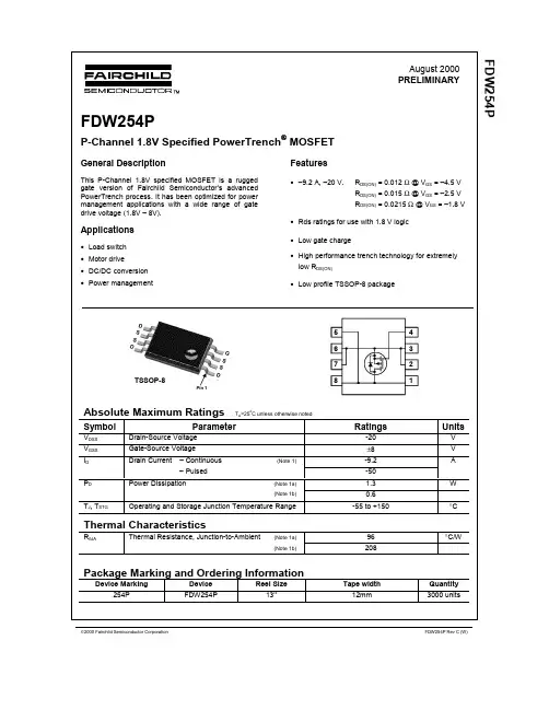
FDW254P中文资料
- 格式:pdf
- 大小:227.22 KB
- 文档页数:6
Preliminary
This is a product that has fixed target specifications but are subject Ramtron International Corporation
to change pending characterization results. 1850 Ramtron Drive, Colorado Springs, CO 80921
(800) 545-FRAM, (719) 481-7000
Rev. 1.0
Aug. 2004
Page 1 of 13 FM25W256
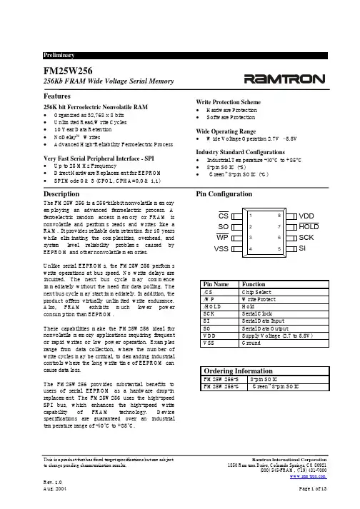
256Kb FRAM Wide Voltage Serial Memory
Features
256K bit Ferroelectric Nonvolatile RAM
• Organized as 32,768 x 8 bits
• Unlimited Read/Write Cycles
• 10 Year Data Retention
• NoDelay™ Writes
• Advanced High-Reliability Ferroelectric Process
Very Fast Serial Peripheral Interface - SPI
• Up to 25 MHz Frequency
• Direct Hardware Replacement for EEPROM
• SPI Mode 0 & 3 (CPOL, CPHA=0,0 & 1,1)
Write Protection Scheme
• Hardware Protection
• Software Protection
Wide Operating Range
• Wide Voltage Operation 2.7V – 5.5V
FE2.1
高速七端口USB2.0集线器控制芯片
一引言
FE2.1芯片是高度集成,高品质,高性能,低能耗,总体花费低的高速七端口USB2.0集线器解决方案。
FE2.1适应多样任务译码器(MMT)风格,借此达到最大的数据输出。六个(而不是两个)非周期数据处理缓冲器被用来将潜在的传输干扰降至最低。整个设计基于状态机控制原理,降低了相应延迟时间。该芯片中没有使用微控制器。
为了保证高品质,整个芯片覆盖测试扫描链—包括高速模块(频率480MHz),所以在运行前可以检测所有逻辑组件。芯片拥有特殊的自检建立模式,可以在封装和测试阶段测试高速、全速和低速模拟前端结束(AFE)元件。
通过使用0.18微米制造工艺和全面电源/时钟控制机制实现低功耗。若无必要,芯片的大部分不会被锁住。 特点:
■ 低功耗:
□七个下行端口全部在高速模式工作时电流为155mA,
□一个下行端口工作在高速模式下电流为66mA,
■ 完全符合通用串行总线规范修订版2.0(USB2.0):
□上传端口支持高速度(480MHz信)和全速(12MHZ)模式;
□7下行端口支持高速(480MHz信),全速(12MHz)和低速(1.5MHz)模式;。 ■集成USB2.0收发器;
■集成上传1.5KΩ上拉电阻、下行1.5KΩ下拉电阻和串行电阻;
■集成5V转3.3V和1.8V的电压调节器;
■集成上电复位电路
■集成12MHz的振荡器与反馈电阻和晶体负载电容;
■集成12MHz转480MHz锁相回路;
■多种任务译码器
□一个任务译码器负责一个下行端口;
□单任务译码器采用备用接口0,多任务译码器用备用接口1;
□每个任务译码器可以处理64个开始分散任务、32个完全分散任务和6个无周期任务;
■只支持自供电模式
■主板配置选项——
□成组或单独的电源控制模式选项;
□全局、多模块或单模块过流保护选项;
□配置可拆卸或不可拆卸下行设备;
DD250/S – DD256/S 1 of 2 © 2006 Won-Top ElectronicsPbDD250/S – DD256/S25A GLASS PASSIVATED DISH TYPE PRESS-FIT DIODEFeatures! Glass Passivated Die Construction! Low Leakage! Low Cost C Anode +! High Surge Current Capability! Low Forward! C-Band Terminal Construction D Mechanical Data B! Case: 8.4mm or 9.5mm Dish Type Press-Fitwith Silicon Rubber Sealed on Top A! Terminals: Contact Areas Readily Solderable! Polarity: Cathode to Case (Reverse Units AreAvailable Upon Request and Are DesignatedBy A “R” Suffix, i.e. DD250R or DD250SR)! Polarity: White Color Equals Standard,Black Color Equals Reverse Polarity! Mounting Position: Any! Lead Free: For RoHS / Lead Free Version,Add “-LF” Suffix to Part Number, See Page 2 “S” Suffix Designates 8.4mm Dish No Suffix Designates 9.5mm DishMaximum Ratings and Electrical Characteristics @TA=25°C unless otherwise specifiedSingle Phase, half wave, 60Hz, resistive or inductive load.For capacitive load, derate current by 20%.CharacteristicSymbolDD250/SDD251/SDD252/SDD253/SDD254/SDD255/SDD256/SUnit Peak Repetitive Reverse Voltage Working Peak Reverse Voltage DC Blocking VoltageVRRMVRWMVR50100200300400500600V RMS Reverse VoltageVR(RMS)3570140210280350420V Average Rectified Output Current @TC = 150°CIO25A Non-Repetitive Peak Forward Surge Current 8.3ms Single half sine-wave superimposed on rated load (JEDEC Method)IFSM300A Forward Voltage @IF = 25AVFM1.0V Peak Reverse Current @TA = 25°C At Rated DC Blocking Voltage @TA = 100°CIRM5.0500µA Typical Junction Capacitance (Note 1)Cj300pF Typical Thermal Resistance (Note 2)RJC1.0°C/W Operating and Storage Temperature RangeTJ, TSTG-65 to +175°CNote:1. Measured at 1.0 MHz and applied reverse voltage of 4.0V D.C.2. Thermal Resistance: Junction to case, single side cooled.WTEPOWER SEMICONDUCTORS
Presence Sensing Safety Devices
Safety Edges
Safedge™ Controllers
Description
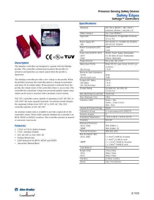
The Safedge controllers are designed to operate with the Safedge
profiles. The controller continuously monitors the profile for
actuation and generates an output signal when the profile is
depressed.
The Safedge controller provides a low voltage to the profile. When
the profile is pressed, the controller detects a change in resistance
and turns off its output relays. When pressure is released from the
profile, the output relays of the controller return to an on state. The
controller has redundant voltage free positively-guided output relays
which can be used to interface with a machine control system.
The ‘251’ controller comes capable of operating at 24V AC/DC, or
120/230V AC from separate terminals. An internal switch changes
the operating voltage from 120V AC to 230V AC. The ‘252’