数据记录仪专业版
- 格式:doc
- 大小:282.00 KB
- 文档页数:7
培养基室清洗机URS目录1.目的 (2)2.范围 (2)3.职责 (3)4.内容 (3)4.1概述 (3)4.2法规要求 (3)4.2.1 GMP要求 (3)4.2.2安全及环保要求 (3)4.3安装要求 (3)4.3.1 安装位置 (3)4.3.2安装尺寸 (4)4.3.3地面承重 (4)4.3.4可用的公用系统 (4)4.3.5洁净级别及房间环境条件 (4)4.3.6 可用的能源配置 (4)4.3.7外观及材质要求 (4)4.4运行要求 (4)4.4.1原辅料、包装材料、产品的规格标准 (4)4.4.2设备效率、产能 (5)4.4.3工艺参数范围(速度、温度等) (5)4.4.4自动部件清洗机系统功能及技术要求 (5)4.5电气、自动控制要求 (6)4.5.1自动控制过程的要求 (7)4.5.1.1报警系统 (7)4.5.1.2警告系统 (7)4.5.1.3软件要求 (7)4.5.1.4控制功能: (7)4.5.1.5系统安全 (8)4.5.2计算机化系统的验证要求 (9)4.6安全要求 (9)4.7文件要求(包括但不限于以下文件) (10)4.8服务要求 (11)4.9洗瓶机主要部件品牌要求 (13)5.附件 (13)1.目的本URS是一份用于从用户的角度定义培养基室清洗机的法规要求、安装要求、运行要求、电气和自动化控制要求、安全要求及文件要求等各方面要求的关键文件。
用于指导用户方、供应商、施工方等各方面人员在清洗机整个生命周期过程中各项活动按要求进行,使所购买的清洗机满足本URS的要求。
2.范围本URS仅用于武汉生物制品研究所有限责任公司培养基室清洗机,包括设计、制造、测试、运输以及安装完成后的调试、验证及培训。
3.职责4.内容4.1概述培养基室需要购买1台自动部件清洗机,必须能用于中试管、血浆瓶(250ml、500ml)的清洗器具的最终清洗,每次可同时清洗中试管数量不少于500支,血浆瓶150个及各类瓶塞200个,也可以用于大试管、取样瓶、扁瓶等的最终清洗。
睡眠- 第一期非快速动眼期睡眠(Stage N1),脑电从alpha波(8-13 Hz)过渡至theta波(4-7 Hz)。
这个阶段与进入睡眠到对象肌肉紧张度和对外界环境觉察度下降有关。
- 第二期非快速动眼期睡眠(Stage N2)过程中,EMG的频率下降,对环境的察觉度消失,这个阶段占整个睡眠的45-55%。
- 第三期非快速动眼期睡眠(Stage N3)过程中,脑电出现delta波(0.5-4 Hz),并且这种波形占所有波形的50%以上。
这被看作是最深度的睡眠阶段。
人类的睡眠是在快速动眼期睡眠(REM)和非快速动眼期睡眠(NREM)之间交替。
药物(例如酒精、安眠药)或者睡眠障碍可以抑制特定的睡眠阶段。
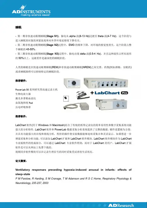
推荐硬件:PowerLab 30系列研究型高速记录主机生物电放大器激光多普勒血流仪血氧饱和度Pod压电呼吸绑带推荐软件:LabChart软件(用于Windows和Macintosh)结合了传统的纸带记录仪的简单易用性和数字采集系统功能强大的分析特性。
LabChart软件和PowerLab数据采集分析系统提供了完整的数据,硬件设置极为方便,并具有功能强大的在线和离线分析,程控的操作使实验数据能够连续采集并和灵活显示。
如果想进一步增强采集和分析功能,可以添加LabChart扩展和LabChart软件模块。
LabChart软件模块作为LabChart 专业版软件的组成部分,可以通过LabChart 专业软件得到;而对于LabChart的用户,LabChart扩展软件是可以从网站上免费下载的。
视频同步软件模块可以在记录生理信号的同时采集受试者的生活状况。
论文摘要:Ventilatory responses preceding hypoxia-induced arousal in infants: effects of sleep-stateP M Parslow, R Harding, S M Cranage, T M Adamson and R S C Horne, Respiratory Physiology & Neurobiology, 235-237, 2003。
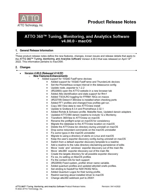
Product Release Notes ATTO 360™ Tuning, Monitoring, and Analytics Softwarev4.00.0 - macOS1. General Release InformationThese product release notes define the new features, changes, known issues and release details that apply to the ATTO 360™ Tuning, Monitoring, and Analytics Software Version 4.00.0 that was released on April 14th 2022. This information pertains to macOS®.2. Changes• Version 4.00.0 (Released 4/14/22)o New Features/Enhancements▪ Added support for 10GbE FastFrame devices• Added support for 10GbE FastFrame and ThunderLink devices• Set the Prometheus scrape interval in the datasource config• Update node_exporter to 1.2.2• (IR22683) open the ATTO website in a new browser tab• Added Atto identification and stats support for ffrm1• Added TSO/LRO toggling for FFRM1 NICs on macos• (IR22709) Detect if 360view is installed when checking ports• Added FF1 profiles and changed how profiles get run.• Copy 360 View data to new ATTOview install• Update to Grafana 8.3.4 and Prometheus 2.32.1• Added Rohde & Schwarz profile. Makefile fixes. Updated darwin adapters• Updated ATTO360 darwin readme to include 12.x Monterey.• Transform 360View to ATTOview on macOS• Rename the preflight script on macOS for consistency• Migrate the database to the ATTOview location on macOS• Delete the ATTOview bin directory during uninstall on macOS• Drop some redundant commands on the macOS uninstaller• Fix some typos in the macOS uninstaller• Migrate to using a directory of alerts on Linux and macOS• Keep the user's exporter discovery config during uninstall on macOS• Switch from a default exporter discovery template to a readme• Add a readme to the rules directory disclaiming persistence of edits• Move `node` and `windows` exporter discovery out of the main file• Move `atto360` exporter discovery out of the main file•Create the targets directory for all possible exporter discovery• Fix sw_lro setting on MacOS profiles• Fix the contact info for tech support• (IR22859) Fixed system_profiler driver name variable.• Added quantum profiles and updated atto/dell onefs profiles.• Set striding to fixedoff for N351/N352 NICs.• Added Quantum Logos for their tuning profile.• Restrict warning about installed driver to macOS• Change atto360 webhook port to 25001•Version 3.10.0 (Released 10/25/21)o New Features/Enhancements▪Added support for macOS 12 Monterrey Operating System▪Added XtendSAN profile iSCSI connectivity on macOS▪Added timestamping to diagnostic events▪Changed Default to home user dir to generate diagnostic bundle▪360 View packaged is now notarized▪360 now raises alert when kernel extension loading is blocked for security reasons▪Alert added for incompatible ThunderLink ports▪Additional alerts added for ATTO devices and FastFrame driver•Version 3.00.2 (Released 6/15/21)o New Features/Enhancements▪Updated CLI tools to include latest ATnetstat▪Addressed active ThunderLink port issues on M1 Mac’s•Version 3.0 (Released 5/13/2021)o New Features/Enhancements▪Added RDMA support▪Added new tuning profiles▪Several new diagnostic alerts added▪New alerts to detect RX miss conditions•Version 2.1 (Released 2/4/2021)o New Features/Enhancements▪Added missing separator line from lro in nic info.▪Removed autoscrollbar from Diagnostic table▪Isilon SMB Profile does not survive reboot▪Added scrollbar to transceiver information popup.▪Cannot set flow control on the N322▪Changed reboot message to only appear on Server Performance profile.▪Add support for Network Services on macOS▪SMB Signing does not change despite tuning profile setting▪Changed TB link rate message to a more descriptive one.▪Changed NIC Info tab to display the port instead of channel▪Add Avid profile▪Fixed visibility of lines separating switch objects.▪Check proper operation of helper app during initialization▪Upgraded WinOF2 to 2.60.50000 and WinMFT to 4.16.0.105•Version 2.0 (Released 10/6/2020)o New Features/Enhancements▪360 View•Launch dashboard from System Information Tab•Shows performance metrics and other statistics collected in a time seriesdatabase▪Added support for MacOS Big Sur▪Created additional optical SFP Statistics and Diagnostics▪Additional bug fixes•Version 1.20 (Released 6/17/2020)o New Features/Enhancements▪Enhanced NIC Statistics adding more data and error statistics▪Created DELL OneFS partner tuning profiles page and added custom OneFS Tuning Profiles for work with SMB, NFS, SMB-Multichannel network shares▪Added support for optical transceiver vendor and diagnostic info▪Added links to ATTO 360 manual in Help menu▪Added support for link speed▪Added support for Thunderbolt Link Rate▪Add diagnostic alert when Thunderbolt link speed is less than devices max capable link speed▪Add diagnostic alert to indicate that packets are being fragmented (Mismatched MTU sizes)▪Parameters can no longer be changed when interface is disabled •Version 1.01 (Released 1/23/2020)o New Features/Enhancements▪Added support for the following Linux Operating Systems•CentOS/RHEL 7•SLES 15 Service Pack 0•Version 1.00 (Released 12/18/2019)o New Features/Enhancements▪Initial Release3. Known Issues/Advisementso On Windows® version changing the scale and layout settings to values over the recommended percentage can cause some unintended behavior we recommend not using values overrecommended settings for best usability.o On the macOS® version initiating tuning profiles can sometimes cause SMB shares to unmount, we recommend unmounting SMB shares before running tuning profiles.o Adjusting MTU sizes can cause 360 to freeze, restart 360 to continue using4. Affected ProductsProduct Name SKUFastFrame3 N322 FFRM-N322-DA0FastFrame3 N351 FFRM-N351-DA0FastFrame3 N352 FFRM-N352-DA0FastFrame3 N311 FFRM-N311-DA0FastFrame3 N312 FFRM-N312-DA0Thunderlink 3102 TLN3-3102-000Thunderlink 3252 TLNS-3252-0005. Contacting ATTO SupportATTO Technology, Inc. is renowned for its technical support services. ATTO’s goal is to provide you the quickest response possible for your technical support needs. Please visithttps:///support/ for hours of operation.ATTO Technical Support can be contacted via phone or email:•Phone: 716.691.1999 ext. 242•E-Mail: ************************。
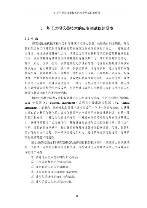
5 基于虚拟仪器技术的应变测试仪的研发5.1 引言应变测量是机械工程中分析零件或结构受力状态、验证设计的正确性、确定整机在实际工作时负载情况和研究某些物理现象机理的重要手段之一,对发展设计理论、保证机械设备安全运行,以及实现自动检测和自动控制等都具有重要的作用。
以应变测量为基础的机械量测量的内容极其广泛,例如测量对象的受力、变形、应力、位移、扭矩,以及材料的力学性质等等。
传统的应变测量仪器以应变仪为主,它由测量电桥、放大器、相敏检波器、低通滤波器、稳压电源和振荡器等组成,如果要显示和记录数据,再配备指示仪表、示波器和记录仪等,构成这样一个测试系统需要多台设备,设备之间必须很好的匹配,设备的选型、调试和使用比较麻烦,而且设备功能单一、固定。
传统应变仪在测量的精度、稳定性和可靠性等方面都已经比较成熟,但仍然难以满足应变测量内容的多样性对应变测量仪器提出的各种不同的要求。
随着计算机的发展,虚拟仪器技术进入测试技术领域,使上述问题迎刃而解。
1986年美国NI(National Instrument)公司首先提出虚拟仪器(VI,Virtual Instrument )的概念,随后虚拟仪器技术逐步形成了一个以计算机为基础,以软件为核心的完整的仪器体系。
虚拟仪器并不完全等同于计算机辅助测试,它是一种新的工业标准,一种现代化的技术规范,一种建立在信号采集与分析理论基础之上,软硬件及其接口实现标准化,具有良好集成性与柔性的仪器体系。
采用这个体系,按照它的规则操作,我们就能充分发挥计算机在数据计算、传输、存储和显示等方面巨大优势,投入最少的财力和人力,通过最方便快捷的途径,得到最高的测量精度和稳定性。
基于虚拟仪器技术的应变测试仪是将虚拟仪器技术应用于应变应力测试领域的一次尝试,研发的主要目的是解决以下传统硬件化应变测试仪器无法或难以实现的几个问题:①多通道应力应变实时图形化显示;②应变采集数据的存储与回放;③任意时刻应力应变值测量;④多参量测量值超极限的自动报警;⑤波形与统计特征值的打印输出;⑥波形的放大与光标跟踪读数。

大亚湾核电站失水事故监视系统改造设计与验证张益林;王源;王旻;刘胜智;季松棣【摘要】针对大亚湾核电站失水事故(LOCA)监视系统(LSS)面临部件老化、备件无法采购导致系统工作不稳定及故障报警闪发的现状,提出对LSS系统进行整体升级的改造方案;描述了新LSS系统采用PLC产品及冗余配置后的设计方案,以及通过对LSS系统的计算模型及接口等关键技术进行研究与分析,并采取各种方法对功能进行验证,完全掌握LSS系统的计算模型,实现LSS系统的自主化设计和改造.%For LOCA Surveillance System (LSS) facing the aging parts, unable to purchase spare parts leading to unstable work and the flash failure alarm of LSS in Daya Bay Nuclear Power Station, the localized modification of the whole upgrading program is proposed. The design of new LSS system after using PLC products and redundant configuration is described. Based on researching and analyzing the key technologies of the calculation model and interface, and adopting various methods to verify the functions of LSS system, the calculation model of LSS system is fully grasped. The independent design and renovation is realized.【期刊名称】《计算机测量与控制》【年(卷),期】2012(020)008【总页数】3页(P2201-2203)【关键词】失水事故监视系统(LSS);部件老化;备件无法采购;设计;验证【作者】张益林;王源;王旻;刘胜智;季松棣【作者单位】中科华核电技术研究院,广东深圳518026;中科华核电技术研究院,广东深圳518026;中科华核电技术研究院,广东深圳518026;大亚湾核电运营管理有限责任公司,广东深圳518124;大亚湾核电运营管理有限责任公司,广东深圳518124【正文语种】中文【中图分类】TL3630 引言失水事故监视系统(LSS)是一个在线堆芯运行监视系统,通过实时或延迟显示数据、曲线来帮助核电站操纵员了解堆芯运行的状态,当发生异常情况时发出报警信号,提醒并辅助操作员控制反应堆状态[1]。
船载航行数据记录仪(VDR)介绍船载航行数据记录仪(VOYAGE DATA RECORDER缩写VDR)是一种船舶安全监控产品,主要用于实时采集、记录船舶航行过程中各种静态、动态航行数据,并将最新一段时期的数据保存于最终存储器,该存储器在船舶失事后有较大的生存可能性,以便打捞出来后,在特定的VDR数据再现设备真实再现船舶发生重大海难或受损前后一段时间内船舶航行状态、驾控人员操作处理情况以作为事故调查,判断事故发生原因的重要依据和处理海事纠纷的重要证据。
其功能相当于飞机上的黑匣子,因而也有人将VDR 称为“船用黑匣子”。
它与飞机黑匣子、汽车黑匣子等同属于电子信息类的安全事件取证和证据保全类产品。
2000年12月国际海事组织(IMO)通过A.861(20)号决议案,要求国际航行及沿海航行船舶均应安装船载航行数据记录仪(VDR)。
国际海事组织第20次大会(1997年11月27日)通过了《船载航行资料记录仪(VDR)性能标准》A.861(20)号决议。
《船载航行资料记录仪(VDR)性能标准》的附件《船载航行资料记录仪(VDR)性能标准建议案》是建议船用黑匣子的最低标准,主要内容有:1. 船用黑匣子是一个完整的系统,包括资料处理,编码,资料介面,记录介质,电源供应和专用备用电源(可充电式VDR辅助电池)和相关项目。
2. 应能连续记录在事故发生期间的有关活动,当船电中断时船舶的应急电源应能供电,当应急电源中断时专用备用电源应供电2 小时。
3. 能记录日期,时间,船位,速度,艏向,驾驶室声音,通信声音,雷达资料和显示后的选择,测深仪,主报警,操舵命令和回应,轮机命令和回应,船体破口状况,水密和防火门状况,横摇和船体应力,风速和风向等。
4. 要求在正常工作状态下应是完全自动的。
能在事故后保存记录资料并恢复和再现这些资料。
与船舶任何设备的连接,都不应妨碍该设备的正常工作,即使船用黑匣子系统出现故障时。
国际海事组织对安装船用黑匣子的建议时间国际海事组织海上安全委员会第72次会议(2000年5月17-26日),决定同意对国际间航行的滚装船和客运船上安装VDR的最后期限;第73次会议(2000年11月27日-12月6日)对各种船舶安装船用黑匣子的建议时间期限为:2002年7月1日及以后建造的客轮;2002年7月1日及以前建造的滚装客船在不晚于2002年7月1日以后的首次检时;2002年7月1日及以后建造除滚装客船以外的客轮不晚于2004年1月1日;2002年7月1日及以后建造的,除旅客轮船以外3000总吨及以上轮船.Ships' “black boxes” and automatic identification systems – regulations enter into force on 1 July 2002New regulations for certain size ships to carry voyage data recorders (VDRs) and automatic identification systems (AISs) enter into force today (1 July 2002).The mandatory regulations are among a raft of amendments to the International Convention for the Safety of Life at Sea, 1974 (SOLAS) entering into force on 1 July 2002. In addition, under its second phase of implementation, the International Management Code for the Safe Operation of Ships and for Pollution Prevention (ISM Code) becomes mandatory for most ships trading internationally on 1 July 2002.The revised SOLAS chapter V (Safety of Navigation), which was adopted in December 2000, includes a number of important new requirements for ships, including those relating to carriage of VDRs and AIS and acceptance of electronic charts as meeting the chart carriage requirements.Voyage data recordersLike the black boxes carried on aircraft, VDRs enable accident investigators to review procedures and instructions in the moments before an incident and help to identify the cause of any accident. Performance standards for VDRs were adopted by IMO in 1997 (IMO resolution A.861(20)) and IMO encourages all ships to carry VDRs.In addition, IMO’s Maritime Safety Committee (MSC) in May 2002 approved MSC/Circ.1024 on Guidelines on Voyage Data Recorders (VDR) ownership to complement the VDR performance standards.VDR requirementsThe following ships are required to carry VDRs, under regulation 20 of the new SOLAS Chapter V:passenger ships constructed on or after 1 July 2002;ro-ro passenger ships constructed before 1 July 2002 not later than the first survey on or after 1 July 2002; passenger ships other than ro-ro passenger ships constructed before 1 July 2002 not later than 1 January 2004; and ships, other than passenger ships, of 3,000 gross tonnage and upwards constructed on or after 1 July 2002.VDRs are required to meet performance standards “not inferior to those adopted by the Organization”. Performance standards for VDRs were adopted in 1997 and give details on data to be recorded and VDR specifications. They state that the VDR should continuously maintain sequential records of preselected data items relating to status and output of the ship's equipment and command and control of the ship. The VDR should be installed in a protective capsule (太空舱) that is brightly coloured and fitted with an appropriate device to aid location. It should be entirely automatic in normal operation. Under the new regulation, the voyage data recorder system, including all sensors, shall be subjected to an annual performance test conducted by an approved testing or servicing facility to verify the accuracy, duration and recoverability of the recorded data.Administrations may exempt ships, other than ro-ro passenger ships, constructed before 1 July 2002, from being fitted with a VDR where it can be demonstrated that interfacing a VDR with the existing equipment on the ship is unreasonable and impracticable.VDRs for existing cargo shipsIn December 2000, IMO’s Maritime Safety Committee (MSC) adopted a resolution on the carriage of VDRs on existing cargo ships, which calls for a feasibility study (可行性研究)to be carried out to ascertain the need for mandatory carriage of VDRs on these ships. The feasibility study, being conducted by the Sub-Committee on Safety of Navigation (and other Sub-Committees as appropriate), takes into account such factors as practicability, technical problems relating to the retrofitting (花样翻新)of VDRs, adequacy of existing performance standards including the possible development of simplified standards, experience in the use of VDRs on ships already fitted with them, including data that could not have been obtained without VDRs, and relevant financial implications, including a cost-benefit analysis.The aim is to finalize the study by 1 January 2004 so that, if the study demonstrates a compelling (强制的)need for mandatory carriage of VDRs on existing cargo ships, relevant amendments to SOLAS Chapter V and the associated performance standards can be drafted. In the meantime, the resolution invites Governments toencourage shipowners to install VDRs on existing cargo ships voluntarily, so that wide experience of their use may be gained.IMO GUIDELINES ON VOYAGE DATA RECORDERS (VDR) OWNERSHIP AND RECOVERY1.) Ownership of VDR/data:The ship owner will, in all circumstances and at all times, own the VDR and its data. however, in the event of an accident the following guidelines would apply.2.) Recovery of VDR:Recovery of the VDR is conditional on the accessibility of the VDR or the data contained therein.a.) In the case of a non-catastrophic (灾难的)accident, recovery of the memory should bestraightforward. For example, in some VDRs it can be accomplished by removal of a hard discfrom the VDR unit. This action will have to be taken soon after the accident to best preserve therelevant evidence for use by both the investigator and the ship owner. As the investigator is veryunlikely to be in a position to instigate this action soon enough after the accident, the owner mustbe responsible, through its on-board standing orders, for ensuring the timely preservation of thisevidence in this circumstance.b.) In the case of abandonment of a vessel during an emergency, masters should, where time andother responsibilities permit, recover the memory and remove it to a place of safety and preserveit until it can be passed to the investigator.c.) In the case of a catastrophic accident, where the VDR is inaccessible and the data has notbeen retrieved prior to abandonment, a decision will need to be taken by the Flag State in co-operation with any other substantially (充分的)interested States on the viability (生存能力)and cost of recovering the VDR balanced against the potential use of the information. If it isdecided to recover the VDR the investigator should be responsible for co-ordinating its recovery.The possibility of the capsule having sustained damage must be considered and specialistexpertise will be required to ensure the best chance of recovering and preserving the evidence. Inaddition the assistance and co-operation of the owners, insurers and the manufacturers of theVDR and those of the protective capsule may be required.3.) Custody (保管)of VDR/data:In all circumstances, during the course of an investigation, the investigator should have custody of the original VDR data, perhaps in the form of the whole or part(s) of the VDR itself, in the same way as if he has custody of other records or evidence under the Code for the Investigation of Marine Casualties and Incidents.4.) Read-out of VDR/data:In all circumstances the responsibility to arrange down loading and read-out of the data from the recovered memory in whatever form should, in the first instance, be undertaken by the investigator who should keep the shipowner fully informed. Additionally, specially in the case of a catastrophic accident where the memory may have sustained damage, the assistance of specialist expertise may be required to ensure the best chance of success.5.) Access to the data:Although the investigator will have custody of the original VDR memory in whatever form for the duration of the investigation, a copy of the data must be provided to the ship owner at an early stage in all circumstances. Further access to the data will be governed by the applicable domestic legislation of the flag state, coastal state and the lead investigating state as appropriate and the guidelines given in the Code for the Investigation of Marine Casualties and Incidents.Data items to be recorded。
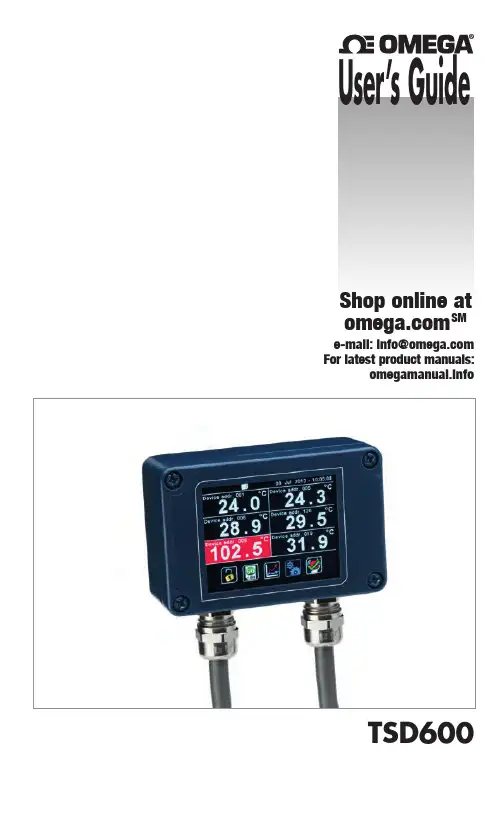
e-mail:**************For latest product manuals:Shop online at SMUser’s GuideTSD6002The information contained in this document is believed to be correct, but OMEGA accepts no liability for any errors it contains, and reserves the right to alter specifications without notice.Servicing North America:U.S.A.:Omega Engineering, Inc., One Omega Drive, P.O. Box 4047S tamford, CT 06907-0047 USAToll-Free: 1-800-826-6342 (USA & Canada only)Customer Service: 1-800-622-2378 (USA & Canada only) Engineering Service: 1-800-872-9436 (USA & Canada only) Tel: (203) 359-1660 Fax: (203) 359-7700 e-mail:**************For Other Locations Visit /worldwide***********************The TSD600 is a temperature indicator, data logger, alarm unit and configuration tool for Omega infrared temperature sensors. It is compatible with all models in the OS210-C4 and OS-MINIHUB series, as well as all OS-MINI and OS-MINIFB models with Modbus output.The TSD600 functions as the Modbus Master on an RS485 network of up to 6 temperature sensors, and can itself be connected as a slave device to another RS485 network via a second, isolated Modbus interface. This allows multiple TSD600 units to be multi-dropped to create a large network of sensors and displays.Optional alarm relay modules allow the TSD600 to be connected to alarm equipment such as sounders and beacons, and optional analogue output modules allow it to be connected to non-Modbus instrumentation.All the configurable parameters for the hub, the connected sensors and the optional output modules are adjustable via the TSD600’s built-in resistive touch screen interface, which can be operated even with gloves on.With an optional MicroSD Card inserted, the TSD600 functions as a fully-configurable data logger. SPECIFICATIONSDisplay 2.83” (72 mm) resistive touch TFT,320 x 240 pixels, backlitSupply Voltage 10 to 30 V DCMaximum Current Draw 100 mAAmbient Temperature Range 0°C to 60°CRelative Humidity Maximum 95%, non-condensing Configurable Parameters (global) Temperature units, date and time, data logging,graph channels, alarm loggingConfigurable Parameters (per channel) Signal processing, emissivity setting, reflected energycompensation, alarms, Modbus addressAlarm Configuration12 alarms (2 per sensor) with adjustable level,individually configurable as HI or LO. Temperature Units °C or °F selectableTemperature Resolution 0.1° below 1000°; 1° above 1000°Signal Processing Average, peak hold, valley hold, minimum, maximum Display Sample Period120 ms per device (720 ms in total for 6 devices) Compatible Sensor Types OS201-C4 (all models),OS-MINIHUB (all models),OS-MINI (-BB and -BRT models),OS-MINIFB (–BRT models)Compatible Output Module Types ICP DAS M-7061 12-channel relay output moduleICP DAS M-7024 4-channel analogue outputmodule, selectable V/mAMECHANICALDimensions98(w) x 64(h) x 36(d) mm excluding cable glands Weight280 g1DATA LOGGINGWith an optional MicroSD Card installed in the slot inside the TSD600, data logging may be manually started and stopped via a button on the temperature display screen, or scheduled to begin at a pre-determined time via the Settings menu.If the TSD600 is connected via the slave interface to another Modbus network, logging may also be started remotely by the Modbus Master on that network.DATA LOGGING SPECIFICATIONSLogging Interval 1 to 86,400 seconds (1 day)MicroSD Card Max. capacity: 32 GB (not included)Internal Clock Battery 1 x BR 1225 3V (not included)Variables Logged T arget temperature, sensing head temperature, alarm events File Format.csv (can be imported to Excel)Configurable Parameters Sample period, number of samples, scheduled start dateand time2The TSD600 has removable screw terminal blocks for the Modbus Slave and Modbus Master interfaces.− Connect the Master interface to the sensors and output modules. Be sure to check the power supply requirements of each device before applying power.− Optionally, connect the Slave interface to another Modbus network with its own Modbus Master such as a PLC or SCADA system.Isolation is provided between the Slave and Master interfaces.MICROSD CARD AND BATTERYThe MicroSD Card and battery slots are located on the touch screen circuit board. Unscrew the lid of the TSD600 to access them.The battery is optional. With a battery fitted, the internal clock will continue to run when the power is off. Without a battery, the unit will request the date and time each time the power is cycled.All other settings are stored in the unit’s permanent memory and will be preserved when it isswitched off, regardless of whether a battery is fitted.3PASSWORDThe default password is 1234. The password may be changed via the touch screen interface.USING THE TOUCH SCREEN INTERFACEVisit for help on how to use the touch screen interface, including a diagramshowing how to navigate to each setting.4MODBUS OVER SERIAL LINE (RS485)INTERFACEBaud rate9600Format8 data, No parity, 1 stop bitReply delay (ms) 20SUPPORTED FUNCTIONSRead register0x03, 0x04Write single register 0x06Write multiple register 0x10The list below includes all available addresses:R = Read, W = Write5SENSOR SETTINGS ADDRESS SPACEThe settings of attached sensors can be read by adding the following offsets to the addresses speci-fied by the sensor manufacturer:See sensor manual for further details.Notes:1. For further information please refer to /specs.php2. Use address 255 to communicate with any connected unit (only one sensor connected)3. Use address 0 to broadcast to all connected units (no response expected)6WARRANTY/DISCLAIMEROMEGA ENGINEERING, INC. warrants this unit to be free of defects in materials and workmanship for a period of 13 months from date of purchase. OMEGA’s WARRANTY adds an additional one (1) month grace period to the normal one (1) year product warranty to cover handling and shipping time. This ensures that OMEGA’s customers receive maximum coverage on each product.If the unit malfunctions, it must be returned to the factory for evaluation. OMEGA’s Customer Service Department will issue an Authorized Return (AR) number immediately upon phone or written request. Upon examination by OMEGA, if the unit is found to be defective, it will be repaired or replaced at no charge. OMEGA’s WARRANT Y does not apply to defects resulting from any action of the purchaser, including but not limited to mishandling, improper interfacing, operation outside of design limits, improper repair, or unauthorized modification. T his WARRANT Y is VOID if the unit shows evidence of having been tampered with or shows evidence of having been damaged as a result of excessive corrosion; or current, heat, moisture or vibration; improper specification; misapplication; misuse or other operating conditions outside of OMEGA’s control. Components in which wear is not warranted, include but are not limited to contact points, fuses, and triacs.OMEGA is pleased to offer suggestions on the use of its various products. However, OMEGA neither assumes responsibility for any omissions or errors nor assumes liability for any damages that result from the use of its products in accordance with information provided by OMEGA, either verbal or written. OMEGA warrants only that the parts manufactured by the company will be as specified and free of defects. OMEGA MAKES NO OTHER WARRANTIES OR REPRESENTATIONS OF ANY KIND WHATSOEVER, EXPRESSED OR IMPLIED, EXCEPT THAT OF TITLE, AND ALL IMPLIED WARRANTIES INCLUDING ANY WARRANTY OF MERCHANTABILITY AND FITNESS FOR A PARTICULAR PURPOSE ARE HEREBY DISCLAIMED. LIMITATION OF LIABILITY: The remedies of purchaser set forth herein are exclusive, and the total liability of OMEGA with respect to this order, whether based on contract, warranty, negligence, indemnification, strict liability or otherwise, shall not exceed the purchase price of the component upon which liability is based. In no event shall OMEGA be liable for consequential, incidental or special damages.CONDITIONS: Equipment sold by OMEGA is not intended to be used, nor shall it be used: (1) as a “Basic Component” under 10 CFR 21 (NRC), used in or with any nuclear installation or activity; or (2) in medical applications or used on humans. Should any Product(s) be used in or with any nuclear installation or activity, medical application, used on humans, or misused in any way, OMEGA assumes no responsibility as set forth in our basic WARRANTY / DISCLAIMER language, and, additionally, purchaser will indemnify OMEGA and hold OMEGA harmless from any liability or damage whatsoever arising out of the use of the Product(s) in such a manner.RETURN REQUESTS/INQUIRIESDirect all warranty and repair requests/inquiries to the OMEGA Customer Service Department. BEFORE RET URNING ANY PRODUCT (S) T O OMEGA, PURCHASER MUST OBT AIN AN AUTHORIZED RETURN (AR) NUMBER FROM OMEGA’S CUSTOMER SERVICE DEPARTMENT (IN ORDER TO AVOID PROCESSING DELAYS). The assigned AR number should then be marked on the outside of the return package and on any correspondence.T he purchaser is responsible for shipping charges, freight, insurance and proper packaging to prevent breakage in transit.OMEGA’s policy is to make running changes, not model changes, whenever an improvement is possible. This affords our customers the latest in technology and engineering.OMEGA is a registered trademark of OMEGA ENGINEERING, INC.© Copyright 2015 OMEGA ENGINEERING, INC. All rights reserved. This document may not be copied, photocopied, reproduced, translated, or reduced to any electronic medium or machine-readable form, in whole or in part, without the prior written consent of OMEGA ENGINEERING, INC.FOR WARRANTY RETURNS, please have the following information available BEFORE contacting OMEGA:1. Purchase Order number under which the product was PURCHASED,2.M odel and serial number of the product under warranty, and 3. R epair instructions and/or specific problems relative to the product.FOR NON-WARRANTY REPAIRS, consult OMEGA for current repair charges. Have the following information available BEFORE contacting OMEGA:1. P urchase Order number to cover the COST of the repair,2. Model and serial number of theproduct, and3. Repair instructions and/or specific problemsrelative to the product.Where Do I Find Everything I NeedforProcess Measurement and Control?OMEGA…Of Course!Shop online at SMTEMPERATUREThermocouple, RTD & Thermistor Probes, Connectors, Panels & AssembliesWire: Thermocouple, RTD & ThermistorCalibrators & Ice Point References Recorders, Controllers & Process MonitorsInfrared Pyrometers PRESSURE, STRAIN AND FORCETransducers & Strain GagesLoad Cells & Pressure Gages Displacement Transducers Instrumentation & Accessories FLOW/LEVEL Rotameters, Gas Mass Flowmeters & Flow ComputersAir V elocity IndicatorsTurbine/Paddlewheel Systems Totalizers & Batch ControllerspH/CONDUCTIVITYpH Electrodes, Testers & Accessories Benchtop/Laboratory Meters Controllers, Calibrators, Simulators & PumpsIndustrial pH & Conductivity Equipment DATA ACQUISITIONData Acquisition & Engineering Software Communications-Based Acquisition SystemsPlug-in Cards for Apple, IBM & CompatiblesData Logging Systems Recorders, Printers & Plotters HEATERSHeating CableCartridge & Strip Heaters Immersion & Band Heaters Flexible HeatersLaboratory Heaters ENVIRONMENTAL MONITORING AND CONTROL Metering & Control Instrumentation RefractometersPumps & TubingAir, Soil & Water Monitors Industrial Water & Wastewater TreatmentpH, Conductivity & Dissolved Oxygen InstrumentsM-5582/0516。

Communicatio ns World Weekly5新闻关注在国内物联网规模商用业务实属不多的当下,车联网一直被业内各方所关注与看好。
目前,中国联通、中国移动等运营商已经联合多家私家车车联网平台供应商与汽车厂商,推出了前装或后装的车联网应用服务,为随后的客车及货车车联网布局起到了示范作用。
为抓住车联网行业机遇,5月31日,国内客车行业领导厂商宇通客车及其合作伙伴中国移动、诺基亚西门子通信在京联合推出了宇通客车车联网产品“安节通”智能运营系统,拥有安全管理、油耗管理、车线管理、维保管理、智能故障管理和司机助手等多项功能,标志着我国客车车联网规模商用已启动。
据悉,安节通车联网平台由诺基亚西门子通信与宇通共同开发,基于诺基亚西门子通信开放、灵活的物联网平台搭建,中国移动负责车联网应用的无线通信与网络服务。
目前,安节通产品已经启动了基本版、专业版与豪华版的销售活动,初期定价分别为人民币2000元、4500元与5700元,宇通内部受访人士向记者表示,上述定价基本无法实现盈利,“对安节通而言,现阶段主要是为了提升客户服务而不是盈利”。
客车车联网需求更为迫切“安全”与“节能”是当前汽车行业最为关注的两大问题,相比私家车,客车由于自身吨位高、油耗大、安全事故后果严重等原因对节能、安全和智能管理的需求更为迫切。
同时,目前行业趋势与客户需求也要求客车企业从提供单一车辆性能保障,转变为提供“人、车、管理”的整体客户运营解决方案。
在上述趋势与需求推动下,目前已有不少客车企业提供了以G S 服务为主的车联网领域的应用,相较而言,此次中国移动、诺基亚西门子通信与宇通联合推出的安节通平台架构更加先进,功能更加完备。
据悉,安节通产品主要由车载终端设备、无线传播媒介、服务器平台三部分组成,具有“安全、节能、高效、方便”四大特征。
其中,车载终端设备包含多功能行车记录仪和司机助手两部分,前者是具有行驶记录功能的卫星定位装置,可识别车辆信号并通过无线设备传输到服务器平台,而后者则是人车交流的平台,集安全提示、故障诊断、维保管理、娱乐视听、视频监控等十大功能于一体;无线传播媒介是车辆与车辆之间、车辆与服务器平台沟通交流的纽带;服务器平台可收集、记录车辆发送的信息并进行数据处理与分析,从而实现运输企业的高效运营。
电影《受益人》观后感范文《受益人》该片讲述了主人公吴海为了给儿子治病,刻意结识了一个与他同样身处边缘和底层的网络女主播淼淼,决心酝酿一场别有用心的婚姻骗局的故事。
下面就是小编给大家带来的电影《受益人》观后感范文,希望大家喜欢!电影《受益人》观后感范文(一)随着电影《少年的你》引起的观影浪潮之后,最近又有几部优秀的国产电影即将上映。
而在这些电影里呼声最高的是一部犯罪喜剧片——《受益人》在国产影视界,说到最火的犯罪喜剧片,大家的第一印象就是陈思成导演的《唐人街探案》系列。
在《唐人街探案》系列电影里,王宝强和刘昊然这对CP给观众们带来了很多的欢笑。
而国产犯罪喜剧片最早让大家熟知的电影是由著名导演宁浩的作品——《疯狂的石头》。
导演宁浩的现实主义的风格受到很多观众们的肯定。
其中影片《疯狂的石头》、《疯狂的赛车》、《疯狂的外星人》这几部电影也是成功的打开了国产犯罪喜剧片的高潮时刻。
2019年11月8日,由宁浩监制,申奥执导,大鹏、柳岩、张子贤主演的电影《受益人》将在全国上映。
这部影片的男女主角选择了喜剧演员大鹏和他的影视CP柳岩,这对CP从《屌丝男士》到《煎饼侠》,一直都是一对“活宝”的存在。
两人相爱相杀却又含着各种喜剧包袱,随时随刻都可能给观众带来感动和欢笑。
电影片名为“受益人”,顾名思义,这部犯罪喜剧电影的故事是关于一次骗保的杀人计划!影片讲述了由大鹏饰演的男主吴海的儿子得了先天哮喘,但这种病的治疗费用非常昂贵。
为了给儿子治病,他联合自己的好友钟振江(张子贤饰)准备欺骗由柳岩饰演的底层的网络女主播淼淼,骗婚骗保!计划设计得相当完美,但是在执行的时候却没有成功。
在两人刚刚开始行动的时候就屡次遭遇各种事故。
吴海觉得是上天不让他这样做,但在好友钟振江的一再怂恿下,他还是硬着头皮继续着计划。
但随着他和淼淼逐渐熟悉,他发现淼淼是一个非常好的女孩,不想为了自己的利益去伤害这个无辜的女孩。
更重要的是,吴海发现自己真的爱上了淼淼!电影《受益人》宣传照最终吴海的良心击败了自己的邪念,他把自己所有的想法全都告诉了淼淼,从为什么接近她到为什么要骗保。
广州虹科电子科技有限公司
广州虹科电子科技有限公司
数据记录仪专业版
单独的数据记录仪,带故障防护数据采集功能
4个CAN总线接口,可选电隔离
数字输入/输出
集成 GPS接收器和 UMTS/GPRS 调制解调器(可选)支持高达 128 GB 容量 CF
卡“热插拔” 独特的触发条件,分组记录信号和信息支持用户定义前置触发缓
冲,大小仅由 CF 卡容量决定 支持 CCP 协议,目前正在开发新的协议应用
工作温度: -40°C to+85°C 通电后快速启动非常低的待用电源消耗
UniCAN 2 Professional是一个基于 µ 控制器单独的数据记录仪,具有高端设备
的优越特性和大容量存储的特点。这是因为:
基本功能直接在硬件(FPGA)层面实现。
独特的 REC09 数据文件管理系统(由 CSM 开发),可处理现代大容量存储卡中
特殊的数据存储问题。
应用领域
主要应用于采集测量数据,以及采集在道路测试、耐久性测试、驱动动力特性,
标定等情况下的 ECU 信息。应用领域有:
轿车、卡车、客车、越野车、大型旅行车
农业、建筑业和特殊用途车辆
飞机、火车和军用车辆
另外,也可应用于新技术的测试和验证,如:
广州虹科电子科技有限公司
广州虹科电子科技有限公司
电动技术
混合动力技术
燃料电池动力技术
配置
UniCAN 2 Professional 目前提供两种方式进行快速、安全和方便的配置:
高达 128 GB 容量的紧凑型闪存卡
GPRS, EDGE, UMTS/3G
CSM也提供在 UniCAN 2 环境(工作温度:-40°C ~+85°C,坚固设计)下使用的
CF 卡,已经经过有故障保护 功能的 CSM REC09 文件系统格式化,并且贴有明
显的标签。
通过 UniCAN 2 Config Tool进行配置,这个新的配置工具强调操作的简单和高
效,具有以下特点:
生成/管理记录仪的配置
对 CF 卡进行格式化、读取、写入操作
为设备调制解调操作和远程数据交换进行配置(SIM卡, FTP 服务器, ...) 车队
管理 用标准软件对数据后期处理进行数据流控制 固件升级 (通过 CF 卡或远
程数据交换)
数据源和输出
UniCAN 2 Professional 可以从不同的数据源记录数据:
CAN, free running 模式(可能的“只听”模式)
使用 CCP 协议的 CAN(Seed & Key 独自按照顾客需 求)
GPS 定位数据和其他内部系统信号 数字输入
此外
可以激活数字输出
广州虹科电子科技有限公司
广州虹科电子科技有限公司
传送 CAN 信息(支持“激活节点”)
数据采集和记录
UniCAN 2 Professional可以同时记录 8个独立通道组的输 入信号变量,和8个
独立信息组的 CAN信息(踪迹)事件驱动。
信号由 DBC或 A2L 描述文件和CANini信号数据库(包括GPS,系统信号)定义。
在通道组内部,每个通道可以设置单独的采样率。信号可以用于不同的通道组,
也可以用单独的采样率记录下来。每个通道组有单独的触发条件,并且可以以线
型和环型方式存储。支持的采样率如下:
CAN信号
100 µs, 200 µs, 500 µs, 1 ms, 2 ms, 5 ms,
10 ms, ... , 10 s, 30 s, 60 s, „, 60 min
GPS 定位数据
250 ms, 500 ms, 1 s, 2 s, „, 60 min
每个信息组 CAN 信息的定义是通过信息滤波器处理的。每个信息组可以有单独
的触发条件,并且可以用线型和环型方式存储。
独特的 REC09 数据文件系统为 CF 卡提供稳定的数据存储条件,保证在突然断
电时没有数据丢失。因此,REC09 数据文件系统实际上为数据记录提供了故障保
护。
记录过程中突然断电和移去 CF 卡不会损坏数据。最多可忽略5秒数据丢失,重
新接入CF卡和恢复电源供应,可以继续记录。
测量数据文件在记录过程中进行压缩。另外,在写入数据到CF 卡的过程中,REC09
数据文件系统执行随机写入优化。
这大大减少了现代大容量存储卡的数据存储开销时间,数据存储开销时间与带小
数据包内存中碎片的递增有关。
启动性能: UniCAN 2Professional可以随时进行测量。根据CF卡配置的复杂度和
容量,大概启动 600ms 后进行数据记 录。
UniCAN 2 Professional的内部时钟周期是1µs,因此,输入 CAN 信息的时间分
辨率是 1 µs。
广州虹科电子科技有限公司
广州虹科电子科技有限公司
另外,可以通过GPS信号,利用实时时钟“高精确度”同步几个 UniCAN 2
Professional。例如,利用这个原理,2 个远程操作的 UniCAN 2 Professional,
可以轻松实现同步,并且自动提供公共目录的数据,以作评估用。
触发条件
使用 UniCAN 2 Config Tool可以对每个独立的通道/信息组定义不同的触发条
件。因此,基本上可以记录所有进入 CAN 的信息。
除了边缘触发、门触发、翻转触发模式, 以下是其它的模式:
用不同逻辑功能结合,可以定义高达 32 个事件/通道条件定义起止时间范围条
件 没有信号 / 信息(循环监测) 错误帧。
前置触发/后置触发
对于每个通道和信息组,可以定义单独的前置和后置触发内存存储区域。这些信
息直接存储在CF卡中,CF卡的容量决定了存储区域大小。
因此,在触发条件满足前,历史数据存储量不受限制。
启动延迟
用户可以设定一个延迟参数(100 ms~60 s),保证在这个时间内的非正常启动状
态信号不予记录。
Wake-On-CAN
可选的附加功能 Wake-On-CAN,在 CAN 总线信息传输时启动记录仪。
存储格式
CF卡上每个通道和信息组的存储有两种方式:
环型存储:当存储容量到达最大时,卡上旧的数据将被新的数据覆盖。
线型存储: 当存储容量到达最大时,测量过程结束。测量数据不再写入卡中。
广州虹科电子科技有限公司
广州虹科电子科技有限公司
单个存储区域最大不能超过 128 GB。
目前,支持在工业温度条件下应用的CF卡最大可达到16GB。
数据流控制
利用 UniCAN 2 Config Tool测量数据有两种传输方式:
从 CF 卡中直接读取数据
通过调制解调器/ FTP 服务器进行远程数据传输获得的测量数据可以进行筛
选,或者转换成其他可以使用标准软件分析数据格式(如 Vector MDF,
ASCII, ...) 。
CF 卡可以在 UniCAN 2 Professional通电的情况下插入或拔出。这种“热插拔”
功能,可以通过更换存储卡来进行大容量数据交换。
为了进行远程传输,用户必须配置模式为“从记录仪到 FTP数据传输”,并且用
UniCAN 2 Config Tool 将传输的数据 转换成文件。
数据传输模式在下列情况是有效的:
点火之后
在预定义时间间隔, 如每个小时数据采集和存储是连续同时进行的
调制解调器连接中断,数据传输将会在调制解调器重新接入网络时继续进行。
为了最大限度保证数据安全和完整,CSM 使用独特的二进制数据传输方式,这种
方式可以使因调制解调器连接中断产生的多余数据最少化,并且在欧洲、美国和
亚洲主要车辆制 造商长期应用中得到了证实。
由 CSM 特别开发的数据后期处理软件控制,自动接通进入FTP 服务器的数据。
测量数据经过分析,并被组合成所需的文件格式(如 MDF),存储在特定的目录
以进行更多处理。
广州虹科电子科技有限公司
广州虹科电子科技有限公司
注释:1) 4 个数字输入/输出. 标准: 3 个数字输入和 1 个数字输出. 也可以
有其他组合。
标准发货清单:
1.UniCAN 2 Professional 带金属盒和安装指引
2.在 Windows 7, Vista 和 XP 平台上运行的 CD,包含 UniCAN 2 Config Tool
(也包括数据后期处理软件)详细的文本资料
广州虹科电子科技有限公司
广州虹科电子科技有限公司
配件:
CAN 分离电缆 最多连接 4 条 CAN 总线
供电电缆 (开线终端), 串接和输入/输出电缆
多种类型天线
UniCAN 2 专业版数据卡,最大 16 GB 容量
其他可选功能:
内置 GPS-模块
16 通道 ANTARIS 4 定位装置, 4 Hz 位置更新频率
内置 GPRS/EDGE/UMTS 调制解调器 电隔离 CAN 总线
Wake-On-CAN