
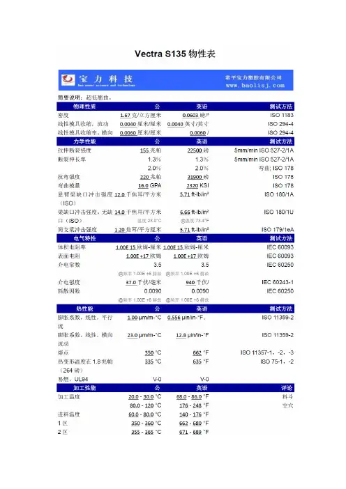
Vectra S135
- 格式:pdf
- 大小:430.94 KB
- 文档页数:2


The VXR-1000 Series is designed to provide extended handheld coverage by repeating transmissions in both di-rections through an existing high power mobile radio.Reliability is assured by a highly integrated surface mount circuit design and a aluminum extrusion chassis. Impor-tant channel frequency data is stored in EEPROM, and is easily programmable by dealers using a personal com-puter and the V ertex Standard VPL-1 Programming Cable and CE-22 Software.Please take a few minutes to read this manual carefully.The information presented here will allow you to derive maximum performance from your VXR-1000. After read-ing it, keep the manual handy for quick reference, in case questions arise later on.We’re glad you joined the Vertex Standard team. Call on us any time, because our business is communications.Let us help you get your message across.This device complies with Part 15 of the FCC rules.Operation is subject to the condition that this de-vice does not cause harmful interference.VXR-1000OPERATING MANUALCopyright 2013Vertex Standard LMR, Inc.All rights reserved.No portion of this manual may be reproducedwithout the permission of Vertex Standard LMR, Inc.C ONTROLS & C ONNECTORS Front Panel Microphone JackConnect the microphone plug to this jack. CHANNEL Selector Knob This knob selects the operating channel.PRI Indicator When on, “PRI ” indicates that the unit is at priority count zero and will repeat all transmissions.TX IndicatorWhen on, “TX ” indicates that the repeater is transmitting to the handheld.COR IndicatorThis lamp blinks red when the VXR-1000 is receiving a sig-nal from a handheld, and glows red while the VXR-1000 is receiving a sub-audible tone from the handheld.MBL IndicatorThis lamp blinks red when the Mobile is receiving signal from repeater or base, and glows red while the Mobile is transmit-ting to the repeater or base.PWR IndicatorThis is the main “P OWER O N ” indicator for the VXR-1000. VOLUME KnobThis knob adjusts the receiver volume.H ARDWARE S ETTINGSJP1004:Controls the output impedance of the transmit audioline to the mobile radio.Short: low-Z (600 Ω); open: high-Z (4.7 k Ω) *JP1005:Controls the maximum drive level of the transmit au-dio output to the mobile.Short: low level output (0-100 mV)*; open: high level output (0-5 V).JP1001/1002/1003:Polarity of Power supply control.Default setting: active high (JP1003: short).VR1001:Mobile Microphone levelVR1002:Mobile RX Audio (External Modulation level)VR1007:Mobile TX Audio (output level)*default setting The VXR-1000 has a fixed 3 minute time-out timer for base to handheld transmissions. If the mobile COR is active for more than 3 minutes it will send a error blip and cease transmission until the mobile COR is inactive.Rear PanelEXT SP (External Speaker)An external loudspeaker may be connected to this 2-contact,3.5-mm mini-phone jack.DSUB 9-Pin Accessory ConnectorExternal TX audio line-input, PTT, external RX audio line-output, and other signals may be obtained from this connec-tor for use with accessories.Antenna SocketThe Antenna socket is a standard 50 Ω BNC antenna connec-tor.F UNCTIONAL D ESCRIPTIONWhen the user leaves the vehicle, they activate their mobile ra-dio via its front panel or a separate switch. When the mobile ra-dio is receiving a signal, the VXR-1000 will begin transmitting on the hand-held’s receive frequency. The user is able to hear and respond to all radio traffic, including other hand-helds on the same frequency. The repeater jumpers and potentiometers are custom-configured for use with the particular mobile radio to which it will be connected. The CE-22 software is used to pro-gram the repeater for the required operating parameters.T RUNKING O PERATIONWhen the radio is connected to a trunking mobile you wish to access the system from your handheld radio, key the handheld briefly then release the PTT key. The radio will attempt to ac-quire a voice channel on the trunking system by keying the mo-bile for 200 mS and monitoring the “on-air detect” line from the mobile. If the VXR-1000 does not see the radio transmit at all (system is busy), it will send a low tone to the handheld to alert you that the system is busy. The radio will automatically retry every 5 seconds and send a “busy” tone to the handheld with each unsuccessful attempt, to indicate progress of the call attempt.If unsuccessful after 30 seconds, the radio will transmit an “in-tercept” tone to alert the handheld that the call attempt failed.When the VXR-1000 detects that the mobile is transmitting, it will continue to monitor the “on-air detect” line until the trans-mitter remains keyed for at least 250 mS to determine if the radio is merely handshaking or retrying. After successful acquisition of a voice channel, it will continue to hold the mobile’s PTT ac-tive for 2 seconds and transmit a “go-ahead” blip to the handheld.You may then key their handheld to speak on the voice channel.If you do not key up within the 2-second period, the radio will un-key the mobile and send the “intercept” tone, as before.S PECIFICATIONSGENERALFrequency Range :150 - 174 MHz (VXR-1000V )450 - 470 MHz (VXR-1000U )Number of Channels :16 Channels Channel Spacing :12.5/25 kHz Supply Voltage :13.8V DCAmbient Temperature Range :−30 °C to +60 °C Frequency Stability :2.5 ppm RF Input-Output Impedance :50 ΩAudio Output Impedance :8 ΩCase Size (WHD):111 x 25.4 x 136 mm Weight :400 gRECEIVERCircuit Type :Double ConversionSuperheterodyneSensitivity (EIA 12dB SINAD ):0.30 µV (VXR-1000V)0.35 µV (VXR-1000U)20 dB Quieting :0.40 µV (VXR-1000V)0.45 µV (VXR-1000U)Squelch Threshold :0.2 µV to 2 µV Adjacent Channel Selectivity :60 dB Intermodulation Rejection :60 dB Spurious and Image Rejection :60 dB Conducted Spurious Emissions :−57 dBm Audio Output : 1 W into 8 Ω w/<5% THD Hum and Noise :40 dB TRANSMITTERPower Output : 5.0/2.5/1.0/0.5 W Modulation :16K0F3E /11K0F3E Maximum Deviation :±5 kHz/2.5 kHz Conducted Spurious Emissions :60 dBc FM Hum and Noise :40 dBO PTIONAL A CCESSORIESMH-53A8J MicrophoneMLS-100External Loudspeaker VPL-1Programming CableCE-22Programming Software (for IBM PC/compatibles only)FRB-4Programming Interface BoxT9101411Radio-to-Radio Cloning Connection Cable(used with the FRB-4 Programming Interface Box)Vertex Standard LMR, Inc.W ARRANTY P OLICYV ertex Standard warrants, to the original purchaser only, its V er-tex Standard manufactured communications products against de-fects in materials and workmanship under normal use and ser-vice for a given period of time from the date of purchase.Limited Warranty Details:North America customers (USA and Canada):/lmr/warranty-terms.aspx Customers outside of North America:Contact the authorized dealer in your country.。

}Rev.1/Add.12/Rev.6/Amend.4E/ECE/324E/ECE/TRANS/50530 December 2009AGREEMENTCONCERNING THE ADOPTION OF UNIFORM TECHNICAL PRESCRIPTIONSFOR WHEELED VEHICLES, EQUIPMENT AND PARTS WHICH CAN BE FITTEDAND/OR BE USED ON WHEELED VEHICLES AND THE CONDITIONS FOR RECIPROCAL RECOGNITION OF APPROVALS GRANTED ON THE BASIS OFTHESE PRESCRIPTIONS ∗/(Revision 2, including the amendments that entered into force on 16 October 1995)_________Addendum 12: Regulation No. 13Revision 6 - Amendment 4Supplement 2 to the 11 series of amendments: Date of entry into force: 24 October 2009UNIFORM PROVISIONS CONCERNING THE APPROVAL OF VEHICLES OF CATEGORIES M, N AND O WITH REGARD TO BRAKING_________UNITED NATIONS∗/ Former title of the Agreement:Agreement Concerning the Adoption of Uniform Conditions of Approval and Reciprocal Recognition of Approval for Motor Vehicle Equipment and Parts, done at Geneva on 20 March 1958.GE.09-}Rev.1/Add.12/Rev.6/Amend.4E/ECE/324E/ECE/TRANS/505Regulation No 13page 2Add new paragraphs 2.35. and 2.36., to read:"2.35. "Subject trailer" is a trailer representative of the trailer type for which type approval is sought.2.36. The "brake factor (B F)" is the input to output amplification ratio of the brake."Add a new paragraph 12.1.8., to read:"12.1.8. As from the official date of entry into force of Supplement 2 to the 11 series of amendments to this Regulation, no Contracting Party applying this Regulation shallrefuse to grant approval under this Regulation as amended by Supplement 2 tothe 11 series of amendments."Add a new paragraph 12.2.7., to read:"12.2.7. As from 48 months after the date of entry into force of Supplement 2 to the 11 series of amendments to this Regulation, Contracting Parties applying this Regulation shallgrant approvals only if the vehicle type to be approved meets the requirements of thisRegulation as amended by Supplement 2 to the 11 series of amendments."Add a new paragraph 12.3.2., to read:"12.3.2. Starting 84 months after the entry into force of Supplement 2 to the 11 series of amendments to this Regulation, Contracting Parties applying this Regulation mayrefuse first national registration (first entry into service) of a vehicle which does notmeet the requirements of Supplement 2 to the 11 series of amendments to thisRegulation."Annex 11,Paragraph 2., amend to read:"2. The term "identical", as used in paragraphs 1.1., 1.2. and 1.3. above, means identical as regards the geometric and mechanical characteristics and the materials used forthe components of the vehicle referred to in those paragraphs.In the case of trailers, these requirements are deemed to be fulfilled, with respect toparagraphs 1.1. and 1.2. above, if the identifiers referred to in Appendix 2,paragraph 3.7. of this Annex for the axle / brake of the subject trailer are contained ina report for a reference axle / brake.A "reference axle / brake" is an axle / brake for which a test report mentioned inAppendix 2, paragraph 3.9. of this annex exists."E/ECE/324E/ECE/TRANS/505}Rev.1/Add.12/Rev.6/Amend.4Regulation No 13page 3Annex 11 - Appendix 1,Table I, amend to read (including footnote 1/):"Axles of the vehicle Reference axlesStatic mass (P) 1/Brakingforce neededat wheelsSpeed Test mass(P e) 1/Brakingforcedeveloped atwheelsSpeedkg N km/h kg N km/h Axle 1Axle 2Axle 3Axle 41/ See paragraph 2.1. of Appendix 2 to this annex"Table III, third row, amend to read (including the deletion of footnote 2/):"REFERENCE AXLE .......………….REPORT NO. ......…… Date .........……..(copy attached)Type-I Type-III Braking force per axle (N)(see paragraph 4.2.1., Appendix 2)Axle 1 Axle 2 Axle 3 T1= ....... % F eT2= ....... % F eT3= ....... % F eT1= ...... % F eT2= ...... % F eT3= ...... % F e… … …" Annex 11 – Appendix 2,Insert a new paragraph 1.2.2., to read:"1.2.2. Tests carried out in accordance with this appendix prior to Supplement 2 to the 11 series of amendments to this Regulation which, together with any supportingdata from the vehicle/axle/brake manufacturer, provide sufficient information tomeet the requirements of Supplement 2 to the 11 series of amendments can be usedfor a new report or the extension of an existing test report without the need to carry-out actual tests."}Rev.1/Add.12/Rev.6/Amend.4E/ECE/324E/ECE/TRANS/505Regulation No 13page 4Paragraph 1.4.1., amend to read:"1.4.1. In the case of air ... shall be adjusted to:s0 > 1.1 · s re-adjust (the upper limit … by the manufacturer),"Paragraph 2., amend to read:"2. SYMBOLS AND DEFINITIONS2.1. SymbolsP = part of the vehicle mass borne by the axle under static conditionsF = normal reaction of road surface on the axle under static conditions = P·gF R= total normal static reaction of road surface on all wheels of trailerF e= test axle loadP e= F e / gg = acceleration due to gravity: g = 9.81 m/s2C = brake input torqueC0= brake input threshold torque, definition see paragraph 2.2.2.C0,dec = declared brake input threshold torqueC max= declared maximum brake input torqueR = tyre rolling radius (dynamic)T = brake force at tyre/road interfaceT R= total brake force at tyre/road interface of the trailerM = brake torque = T·Rz = braking rate = T/F or M/(R·F)s = actuator stroke (working stroke plus free stroke)s p= see Annex 19, Appendix 7Th A= see Annex 19, Appendix 7l = lever lengthr = internal radius of brake drums or effective radius of brake discsp = brake actuation pressureNote: Symbols with the suffix "e" relate to the parameters associated with the reference brake test and may be added to other symbols as appropriate.2.2. Definitions2.2.1. Mass of a disc or drum2.2.1.1. The "declared mass" is the mass declared by the manufacturer which is arepresentative mass for the brake identifier (see paragraph 3.7.2.2. of this appendix).2.2.1.2. The "nominal test mass" is the mass which the manufacturer specifies for the disc ordrum with which the relevant test is carried out by the Technical Service.}Rev.1/Add.12/Rev.6/Amend.4E/ECE/324E/ECE/TRANS/505Regulation No 13page 52.2.1.3. The "actual test mass" is the mass measured by the Technical Service prior to thetest.2.2.2. "Brake input threshold torque":2.2.2.1. The brake input threshold torque "C0" is the input torque necessary to produce ameasurable brake torque. This torque may be determined by extrapolation ofmeasurements within a range not exceeding 15 percent braking rate or otherequivalent methods (e.g. Annex 10, paragraph 1.3.1.1.).2.2.2.2. The brake input threshold torque "C0,dec" is the brake input threshold torque declaredby the manufacturer which is a representative brake input threshold torque for thebrake (see paragraph 3.7.2.2.1. of this appendix) and is needed to produce diagram 2of Annex 19.2.2.2.3. The brake input threshold torque "C0,e" is determined by the procedure as defined inparagraph 2.2.2.1. above, measured by the Technical Service at the end of the test. 2.2.3. "External diameter of a disc":2.2.3.1. The "declared external diameter" is the external diameter of a disc declared by themanufacturer which is a representative external diameter for the disc (seeparagraph 3.7.2.2.1. of this appendix).2.2.3.2. The "nominal external diameter" is the external diameter which the manufacturerspecifies for the disc on which the relevant test is carried out by the TechnicalService.2.2.3.3. The "actual external diameter" is the external diameter measured by the TechnicalService prior to the test.2.2.4. The "effective length of the cam shaft" is the distance from the centre line of theS-cam to the centre line of the operating lever."Paragraph 3.4., amend to read:"3.4. Test conditions (general)"Paragraphs 3.7. to 3.7.3., should be deleted.Insert new paragraphs 3.7. to 3.9.4., to read:"3.7. Identification}Rev.1/Add.12/Rev.6/Amend.4E/ECE/324E/ECE/TRANS/505Regulation No 13page 63.7.1. The axle shall carry in a visible position at least the following identificationinformation grouped together, in any order, in a legible and indelible manner:(a) Axle manufacturer and/or make;(b) Axle identifier (see paragraph 3.7.2.1. of this appendix);(c) Brake identifier (see paragraph 3.7.2.2. of this appendix);(d) F e identifier (see paragraph 3.7.2.3. of this appendix);(e) Base part of test report number (see paragraph 3.9. of this appendix).An example is given below:Axle Manufacturer and/or make ABCID1-XXXXXXID2-YYYYYYID3-11200ID4-ZZZZZZZ3.7.1.1. A non-integrated automatic brake adjustment device shall carry in a visible positionat least the following identification information grouped together, in a legible andindelible manner:(a) Manufacturer and/or make;(b) Type;(c) Version.3.7.1.2. The make and type of each brake lining shall be visible when the lining/pad ismounted on the brake shoe / back plate in a legible and indelible manner.3.7.2. Identifiers3.7.2.1. Axle identifierThe axle identifier categorizes an axle in terms of its braking force/torque capabilityas stated by the axle manufacturer.The axle identifier shall be an alphanumeric number consisting of the four characters"ID1-" followed by a maximum of 20 characters.3.7.2.2. Brake identifierThe brake identifier shall be an alphanumeric number consisting of the fourcharacters "ID2-" followed by a maximum of 20 characters.A brake with the same identifier is a brake which does not differ with regard to thefollowing criteria:}Rev.1/Add.12/Rev.6/Amend.4E/ECE/324E/ECE/TRANS/505Regulation No 13page 7(a) Type of brake (e.g. drum (S-cam, wedge, etc.) or disc brake (fixed, floating,single or twin disc, etc.));(b) Base material (e. g. ferrous or non ferrous) with respect to calliper housing,brake carrier, brake disc and brake drum;(c) Dimensions with the suffix "e" according to figures 2A and 2B of Appendix 5of this annex;(d) The basic method used within the brake to generate the braking force;(e) In the case of disc brakes, the friction ring mounting method: fixed or floating;(f) Brake factor B F;(g) Different brake characteristics with respect to the requirements of Annex 11which are not covered by subparagraph 3.7.2.2.1.3.7.2.2.1. Differences allowed within the same brake identifierThe same brake identifier may include different brake characteristics with regard tothe following criteria:(a) Increase in maximum declared brake input torque C max;(b) Deviation of declared brake disc and brake drum mass m dec: ± 20 per cent;(c) Method of attachment of the lining / pad on the brake shoe / back plate;(d) In the case of disc brakes, increase of maximum stroke capability of the brake;(e) Effective length of the cam shaft;(f) Declared threshold torque C0,dec;(g) ± 5 mm from the declared external diameter of the disc;(h) Type of cooling of the disc (ventilated/non-ventilated);(i) Hub (with or without integrated hub);(j) Disc with integrated drum – with or without parking brake function;(k) Geometric relationship between disc friction surfaces and disc mounting;(l) Brake lining type;(m) Material variations (excluding changes in base material, see paragraph 3.7.2.2.) for which the manufacturer confirms that such a material variation does notchange the performance with respect to the required tests;(n) Back plate and shoes.3.7.2.3. F e identifierThe F e identifier indicates the test axle load. It shall be an alphanumeric numberconsisting of the four characters "ID3-" followed by the F e value in daN, without the"daN" unit identifier.E/ECE/324E/ECE/TRANS/505}Rev.1/Add.12/Rev.6/Amend.4Regulation No 13page 83.7.2.4. Test report identifierThe test report identifier shall be an alphanumeric number consisting of the fourcharacters "ID4-" followed by the base part of the test report number.3.7.3. Automatic brake adjustment device (integrated and non-integrated)3.7.3.1. Types of automatic brake adjustment deviceThe same type of automatic brake adjustment device does not differ with regard tothe following criteria:(a) Body: base material (e. g. ferrous or non ferrous, cast iron or forged steel);(b) Maximal permitted brake shaft moment;(c) Adjustment operating principle, e.g. stroke (travel) dependent, force dependentor electronic/mechanical.3.7.3.2. Versions of automatic brake adjustment device, with respect to the adjustmentbehaviourAutomatic brake adjustment devices within a type that have an impact on the runningclearance of the brake are considered to be different versions.3.8. Test criteriaThe testing shall demonstrate compliance with all the requirements laid down inAppendix 2 of this annex.In the case that a new test report, or a test report extension, is required for a modifiedaxle/brake within the limits specified in paragraph 3.7.2.2.1. the following criteriaare used to determine the necessity for further testing taking into account worst caseconfigurations agreed with the Technical Service.Abbreviations shown below are used in the subsequent table:CT (complete test) Test according to Annex 11, Appendix 2:3.5.1.: Supplementary cold performance test3.5.2.: Fade test (Type-I test) */3.5.3.: Fade test (Type-III test) */Test according to Annex 19:4.: Cold performance characteristics for trailer brakes*/FT (fade test) Test according to Annex 11, Appendix 2:3.5.1.: Supplementary cold performance test3.5.2.: Fade test (Type-I test) */3.5.3.: Fade test (Type-III test) */*/ If applicableE/ECE/324E/ECE/TRANS/505}Rev.1/Add.12/Rev.6/Amend.4Regulation No 13page 9Differences according toparagraph 3.7.2.2.1. aboveTest criteria(a) Increase in maximum declared brakeinput torque C maxChange allowed without additional testing(b) Deviation of declared brake disc andbrake drum mass m dec: ± 20 per cent CT: The lightest variant shall be tested if the nominal test mass for a new variant deviates less than 5 per cent from a previously tested variant with a higher nominal value then the test of the lighter version may be dispensed with.The actual test mass of the test specimen may vary ± 5 per cent from the nominal test mass.(c) Method of attachment of the lining /pad on the brake shoe / back plate The worst case specified by the manufacturer and agreed by the Technical Services conducting the test(d) In the case of disc brakes, increase ofmaximum stroke capability of thebrakeChange allowed without additional testing(e) Effective length of the cam shaft The worst case is considered to be the lowest cam shaft torsional stiffness and shall be verified by either:(i) FT or(ii) Change allowed without additional testing if by calculation the influence with respect to stroke and braking force can be shown. In this case the test report shall indicate the following extrapolated values: s e, C e, T e, T e/F e,(f) Declared threshold torque C0,dec It shall be checked that the brake performance remains within the corridors of Diagram 2 of Annex 19.(g) ± 5 mm from the declared externaldiameter of the disc The worst case test is considered the smallest diameterThe actual external diameter of the test specimen may vary ± 1 mm from the nominal external diameter specified by the axle manufacturer.(h) Type of cooling of the disc(ventilated/non-ventilated)Each type shall be tested(i) Hub (with or without integrated hub) Each type shall be tested(j) Disc with integrated drum – with orwithout parking brake functionTesting is not required for this feature (k) Geometric relationship between discfriction surfaces and disc mountingTesting is not required for this feature (l) Brake lining type Each type of brake liningE/ECE/324E/ECE/TRANS/505}Rev.1/Add.12/Rev.6/Amend.4Regulation No 13page 10Differences according toparagraph 3.7.2.2.1. aboveTest criteria (m) Material variations (excludingchanges in base material, seeparagraph 3.7.2.2.) for which themanufacturer confirms that such amaterial variation does not changethe performance with respect to therequired testsTest not required for this condition(n) Back plate and shoes Worst case test conditions */:Back plate: minimum thickness Shoe: lightest brake shoe*/ No test is required if the manufacturer can demonstrate that a change does not effect the stiffness3.8.1. If an automatic brake adjustment device deviates from a tested one according toparagraphs 3.7.3.1. and 3.7.3.2. an additional test according to paragraph 3.6.2. ofthis appendix is necessary.3.9. Test report3.9.1. Test report numberThe test report number consists of two parts: a base part and a suffix which identifiesthe issue level of the test report.The base part, consisting of a maximum of 20 characters, and suffix shall be clearlyseparated from each other using e.g. a dot or slash.The base part of the test report number shall only cover brakes with the same brakeidentifier and the same brake factor (according to paragraph 4. of Annex 19 to thisRegulation).3.9.2. Test codeIn addition to the test report number a "test code" consisting of up to eight characters(e.g. ABC123) shall indicate the test results applicable to the identifiers and the testspecimen, which is described by the details given in paragraph 3.7. above.3.9.3. Test results3.9.3.1. The result of tests carried out in accordance with paragraphs 3.5. and 3.6.1. of thisappendix shall be reported on a form, a model of which is shown in Appendix 3 tothis annex.3.9.3.2.In the case of a brake installed with an alternative brake adjustment device the results of tests carried out in accordance with paragraph 3.6.2. of this appendix shall be reported on a form, a model of which is shown in Appendix 4 to this annex. 3.9.4. Information documentAn information document, provided by the axle or vehicle manufacturer, containing at least the information defined in Appendix 5 to this annex shall be part of the Test Report.The information document shall identify, if applicable, the various variants of the brake/axle equipment with respect to the essential criteria listed in paragraph 3.7.2.2.1. above."Paragraph 4.1., amend to read: "4.1. Verification of componentsThe brake specification of the vehicle to be type approved shall comply with the requirements laid down in paragraphs 3.7. and 3.8. above"Paragraphs 4.1.1. to 4.1.7., should be deleted. Paragraph 4.3.1.4., the formula, amend to read:()F 0.01RR C C C C F 0.01T T eoe e o e e ⋅+⋅−−⋅−=Paragraph 4.3.2., the formula, amend to read:F T = F T RRΣΣpage 12Annex 11 – Appendix 3, amend to read (including the deletion of figures 1A, 1B, 2A and 2B):"Annex 11 – Appendix 3MODEL TEST REPORT FORM AS PRESCRIBED IN PARAGRAPH 3.9.OF APPENDIX 2 TO THIS ANNEXTEST REPORT No. ………Base part: ID4- ………Suffix: ……………1. General1.1. Axle manufacturer (name and address): ..........................................................................1.1.1. Make of axle manufacturer:..............................................................................................1.2. Brake manufacturer (name and address): .........................................................................1.2.1. Brake identifier ID2-:........................................................................................................1.2.2. Automatic brake adjustment device: integrated/non-integrated 1/1.3. Manufacturer's Information Document: ...........................................................................2. Test RecordThe following data has to be recorded for each test:2.1. Test code (see paragraph3.9.2. of Appendix 2 of this annex): ........................................2.2. Test specimen: (precise identification of the variant tested related to theManufacturer's Information Document. See also paragraph 3.9.2. of Appendix 2 of thisannex)2.2.1. Axle2.2.1.1. Axle identifier: ID1-..........................................................................................................2.2.1.2. Identification of tested axle: .............................................................................................2.2.1.3. Test axle load (Fe identifier): ID3-............................................................................daN 2.2.2. Brake2.2.2.1. Brake identifier: ID2-........................................................................................................2.2.2.2. Identification of tested brake: ...........................................................................................2.2.2.3. Maximum stroke capability of the brake 2/:.....................................................................2.2.2.4. Effective length of the cam shaft 3/:.................................................................................2.2.2.5. Material variation as per paragraph3.8 (m) of Appendix 2 of this annex: ......................2.2.2.6. Brake drum / disc 1/2.2.2.6.1. Actual test mass of disc / drum 1/: ...................................................................................2.2.2.6.2. Nominal external diameter of disc 2/: ..............................................................................2.2.2.6.3. Type of cooling of the disc ventilated/non-ventilated 1/2.2.2.6.4. With or without integrated hub 1/2.2.2.6.5. Disc with integrated drum – with or without parking brake function 1/ 2/2.2.2.6.6. Geometric relationship between disc friction surfaces and disc mounting:......................2.2.2.6.7. Base material:....................................................................................................................2.2.2.7. Brake lining or pad 1/2.2.2.7.1. Manufacturer:....................................................................................................................2.2.2.7.2. Make:................................................................................................................................2.2.2.7.3. Type:.................................................................................................................................2.2.2.7.4. Method of attachment of the lining / pad on the brake shoe / back plate 1/: ...................2.2.2.7.5. Thickness of back plate, weight of shoes or other describing information(Manufacturer's Information Document) 1/:.....................................................................2.2.2.7.6. Base material of brake shoe / back plate 1/:......................................................................2.2.3. Automatic brake adjustment device (not applicable in the case of integrated automaticbrake adjustment device) 1/2.2.3.1. Manufacturer (name and address): ...................................................................................2.2.3.2. Make:................................................................................................................................2.2.3.3. Type:.................................................................................................................................2.2.3.4. Version:.............................................................................................................................2.2.4. Wheel(s) (dimensions see Figures 1A and 1B in Appendix 5 of this annex)2.2.4.1. Reference tyre rolling radius (R e) at test axle load (F e): ..................................................2.2.4.2. Data of the fitted wheel during testing:Tyre size Rim size X e (mm) D e (mm) E e (mm) G e (mm) 2.2.5. Lever length le: ................................................................................................................2.2.6. Brake actuator2.2.6.1. Manufacturer: ...................................................................................................................2.2.6.2. Make: ...............................................................................................................................2.2.6.3. Type: ................................................................................................................................2.2.6.4. (Test) Identification number: ...........................................................................................2.3. Test results (corrected to take account of rolling resistance of 0.01·F e)2.3.1. In the case of vehicles of categories O2 and O3Test type: 0 IAnnex 11, Appendix 2, paragraph: 3.5.1.2. 3.5.2.2./3. 3.5.2.4.Test speed km/h 40 40 40Brake actuator pressure p e kPa -Braking time min - 2.55 -Brake force developed T e daNBrake efficiency T e/F e-Actuator stroke s e mm -Brake input torque C e Nm -Brake input threshold torque C0,e Nm -page 142.3.2. In the case of vehicles of category O4Test type: 0 III Annex 11, Appendix 2, paragraph: 3.5.1.2. 3.5.3.1. 3.5.3.2.Test speed initial km/h 60 60Test speed final km/hBrake actuator pressure p e kPa -Number of brake applications - - 20 -Duration of braking cycle s - 60 -Brake force developed T e daNBrake efficiency T e/F e-Actuator stroke s e mm -Brake input torque C e Nm -Brake input threshold torque C0,e Nm -2.3.3. This item is to be completed only when the brake has been subject to the testprocedure defined in paragraph 4. of Annex 19 to this Regulation to verify the coldperformance characteristics of the brake by means of the brake factor (B F).2.3.3.1. Brake factor B F:2.3.3.2. Declared threshold torque C0,dec Nm2.3.4. Performance of the automatic brake adjustment device (if applicable)2.3.4.1. Free running according to para. 3.6.3. of Annex 11, Appendix 2: yes / no 1/3. Application rangeThe application range specifies the axle/brake variants that are covered in this testreport, by showing which variables are covered by the individual test codes.4. This test has been carried out and the results reported in accordance with Appendix 2to Annex 11 and where appropriate paragraph 4. of Annex 19 to Regulation No. 13 aslast amended by the ... series of amendments.At the end of the test defined in paragraph 3.6. of Annex 11, Appendix 2, 4/ therequirements of paragraph 5.2.2.8.1. of Regulation No. 13 were deemed to be fulfilled/ not fulfilled. 1/Technical Service 5/ carrying out the testSigned: ....................................... Date: ........................................5. Approval Authority 5/Signed: ....................................... Date: ........................................。