MAX3076EEPD+中文资料
- 格式:pdf
- 大小:507.04 KB
- 文档页数:25
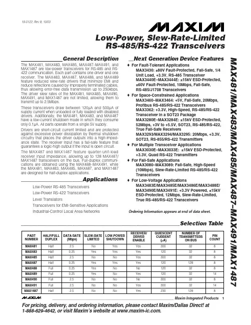
General Description
The MAX3070E–MAX3079E 3.3V, ±15kV ESD-protected,
RS-485/RS-422 transceivers feature one driver and one
receiver. These devices include fail-safe circuitry, guar-
anteeing a logic-high receiver output when receiver
inputs are open or shorted. The receiver outputs a logic
high if all transmitters on a terminated bus are disabled
(high impedance). The MAX3070E–MAX3079E include a
hot-swap capability to eliminate false transitions on the
bus during power-up or hot insertion.
The MAX3070E/MAX3071E/MAX3072E feature reduced
slew-rate drivers that minimize EMI and reduce reflec-
tions caused by improperly terminated cables, allowing
error-free data transmission up to 250kbps. The
MAX3073E/MAX3074E/MAX3075E also feature slew-
rate-limited drivers but allow transmit speeds up to
500kbps. The MAX3076E/MAX3077E/MAX3078E driver
slew rates are not limited, making transmit speeds up to
16Mbps possible. The MAX3079E slew rate is pin
selectable for 250kbps, 500kbps, and 16Mbps.
The MAX3072E/MAX3075E/MAX3078E are intended for
half-duplex communications, and the MAX3070E/
MAX3071E/MAX3073E/MAX3074E/MAX3076E/MAX307
7E are intended for full-duplex communications. The
MAX3079E is selectable for half-duplex or full-duplex
operation. It also features independently programmable
receiver and transmitter output phase through
separate pins.
The MAX3070E–MAX3079E transceivers draw 800µA
of supply current when unloaded or when fully loaded
with the drivers disabled. All devices have a 1/8-unit
load receiver input impedance, allowing up to 256transceivers on the bus.
Applications
Lighting Systems
Industrial Control
Telecom
Security Systems
InstrumentationFeatures
o3.3V Operation
oElectrostatic Discharge (ESD) Protection for
RS-485 I/O Pins
±15kV Human Body Model
oTrue Fail-Safe Receiver While Maintaining
EIA/TIA-485 Compatibility
oHot-Swap Input Structure on DE and RE
oEnhanced Slew-Rate Limiting Facilitates Error-
Free Data Transmission
(MAX3070E–MAX3075E/MAX3079E)
oLow-Current Shutdown Mode (Except
MAX3071E/MAX3074E/MAX3077E)
oPin-Selectable Full-/Half-Duplex Operation
(MAX3079E)
oPhase Controls to Correct for Twisted-Pair
Reversal (MAX3079E)
oAllow Up to 256 Transceivers on the Bus
oAvailable in Industry-Standard 8-Pin SO Package
MAX3070E–MAX3079E+3.3V, ±15kV ESD-Protected, Fail-Safe,
Hot-Swap, RS-485/RS-422 Transceivers
________________________________________________________________Maxim Integrated Products
1Ordering Information19-2668; Rev 1; 1/03
For pricing, delivery, and ordering information,please contact Maxim/Dallas Direct!at
1-888-629-4642, or visit Maxim’s website at www.maxim-ic.com.
PARTTEMP RANGEPIN-PACKAGE
MAX3070EEPD-40°C to +85°C14 Plastic DIP
MAX3070EESD-40°C to +85°C14 SO
MAX3070EAPD-40°C to +125°C14 Plastic DIP
MAX3070EASD-40°C to +125°C14 SO
MAX3071EEPA-40°C to +85°C8 Plastic DIP
MAX3071EESA-40°C to +85°C8 SO
MAX3071EAPA-40°C to +125°C8 Plastic DIP
MAX3071EASA-40°C to +125°C8 SO
Selector Guide, Pin Configurations, and Typical Operating
Circuits appear at end of data sheet.Ordering Information continued at end of data sheet.元器件交易网www.cecb2b.com
MAX3070E–MAX3079E+3.3V, ±15kV ESD-Protected, Fail-Safe,
Hot-Swap, RS-485/RS-422 Transceivers
2
_______________________________________________________________________________________ABSOLUTE MAXIMUM RATINGS
DC ELECTRICAL CHARACTERISTICS(V
CC= 3.3V ±10%, T
A=T
MINto T
MAX, unless otherwise noted. Typical values are at V
CC= 3.3V and T
A= +25°C.) (Note 1)Stresses beyond those listed under “Absolute Maximum Ratings” may cause permanent damage to the device. These are stress ratings only, and functional
operation of the device at these or any other conditions beyond those indicated in the operational sections of the specifications is not implied. Exposure to
absolute maximum rating conditions for extended periods may affect device reliability.(All voltages referenced to GND)
Supply Voltage (V
CC).............................................................+6V
Control Input Voltage (RE, DE, SLR,
H/F, TXP, RXP)......................................................-0.3V to +6V
Driver Input Voltage (DI)...........................................-0.3V to +6V
Driver Output Voltage (Z, Y, A, B).............................-8V to +13V
Receiver Input Voltage (A, B)....................................-8V to +13V
Receiver Input Voltage
Full Duplex (A, B)..................................................-8V to +13V
Receiver Output Voltage (RO)....................-0.3V to (V
CC+ 0.3V)
Driver Output Current.....................................................±250mAContinuous Power Dissipation (T
A= +70°C)
8-Pin SO (derate 5.88mW/°C above +70°C).................471mW
8-Pin Plastic DIP (derate 9.09mW/°C above +70°C).....727mW