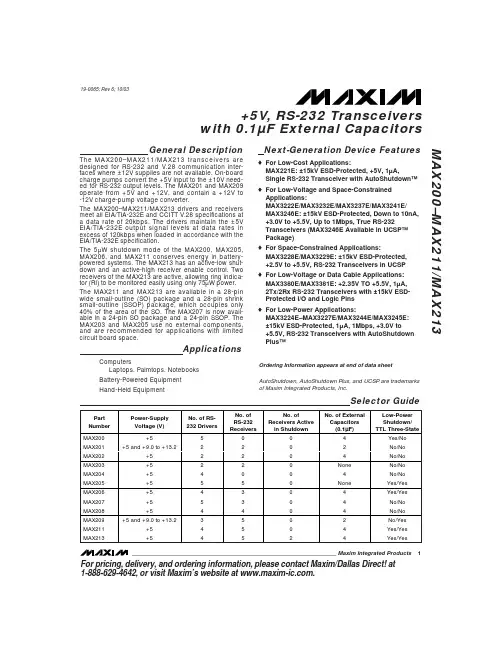
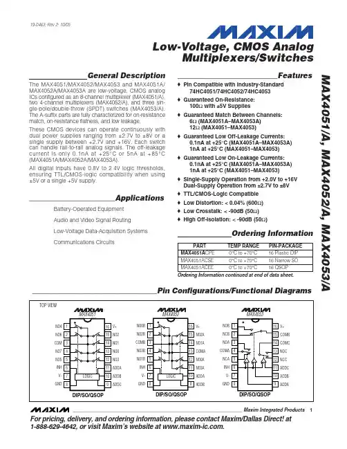
MAX1843ETI+中文资料
- 格式:pdf
- 大小:850.08 KB
- 文档页数:13
MAX18432.7A, 1MHz, Low-Voltage, Step-Down Regulator with
Internal Synchronous Rectification in TQFN Package
________________________________________________________________Maxim Integrated Products119-1986; Rev 2; 4/06
General Description
The MAX1843 constant-off-time, pulse-width modulated(PWM) step-down DC-DC converter is ideal for use in 5Vand 3.3V to low-voltage conversion necessary in note-book and subnotebook computers. This device featuresan internal PMOS power switch and internal synchronousrectification for high efficiency and reduced componentcount. An external Schottky diode is not required. Theinternal 90mΩpower switch and 70mΩnMOS synchro-nous-rectifier switch easily deliver continuous load cur-rents up to 2.7A. The MAX1843 produces a preset +2.5V,+1.8V, or +1.5V output voltage or an adjustable outputfrom +1.1V to VIN. It achieves efficiencies as high as95%.
The MAX1843 uses a unique current-mode, constant-off-time, PWM control scheme, which includes Idle Mode™to maintain high efficiency during light-load operation.The programmable constant-off-time architecture setsswitching frequencies up to 1MHz, allowing the user tooptimize performance trade-offs between efficiency, out-put switching noise, component size, and cost. TheMAX1843 features an adjustable soft-start to limit surgecurrents during startup, a 100% duty-cycle mode for lowdropout operation, and a low-power shutdown mode thatdisconnects the input from the output and reduces sup-ply current below 1µA. The MAX1843 is available in a 28-pin TQFN package with an exposed backside pad.
Applications
5V or 3.3V to Low-Voltage Conversion
CPU I/O Ring
Chipset Supplies
Notebook and Subnotebook ComputersFeatures
♦±1% Output Accuracy
♦Up to 1MHz Switching Frequency
♦95% Efficiency
♦Internal pMOS/nMOS Switches
90mΩ/70mΩOn-Resistance at VIN= +4.5V 110mΩ/80mΩOn-Resistance at VIN= +3V
♦Output Voltage
+2.5V, +1.8V, or +1.5V Pin Selectable+1.1V to VINAdjustable
♦+3V to +5.5V Input Voltage Range
♦350µA Operating Supply Current
♦< 1µA Shutdown Supply Current
♦Programmable Constant-Off-Time Operation
♦Idle Mode Operation at Light Loads
♦Thermal Shutdown
♦Adjustable Soft-Start Inrush Current Limiting
♦100% Duty Cycle During Low-Dropout Operation
♦Output Short-Circuit Protection
♦28-Pin TQFN Package
Ordering Information
Idle Mode is a trademark of Maxim Integrated Products, Inc.
MAX
18432526
27
2822
23
24
8910111213
234567LXINSSCOMPINN.C.LXLXPGNDVCCFBSELPGNDPGND
TQFNTOP VIEW
N.C.+11415161718192021
REF
GND
N.C.
N.C.N.C.
FB
TOFFN.C.
LXN.C.
LX
N.C.
SHDN
N.C.Pin Configuration
TOFF
COMPVCC
FBSELSHDNIN
PGND
GND
REFSSLX
FBMAX1843OUTPUT+1.1V TOVININPUT+3V TO +5.5V
0.01µF1µF2.2µF470pF10ΩTypical Configuration
For pricing, delivery, and ordering information,please contact Maxim/Dallas Direct!at
1-888-629-4642, or visit Maxim’s website at www.maxim-ic.com.PARTTEMPRANGEPIN-PACKAGEPKGCODEMAX1843ETI+-40°C to +85°C28 TQFNT2855-6
+Denotes lead-free package.元器件交易网www.cecb2b.com
MAX18432.7A, 1MHz, Low-Voltage, Step-Down Regulator with
Synchronous Rectification in TQFN Package
2_______________________________________________________________________________________ABSOLUTE MAXIMUM RATINGS
ELECTRICAL CHARACTERISTICS
(VIN= VCC= +3.3V, FBSEL = GND, TA= 0°C to +85°C, unless otherwise noted. Typical values are at TA= +25°C.)Stresses beyond those listed under “Absolute Maximum Ratings” may cause permanent damage to the device. These are stress ratings only, and functionaloperation of the device at these or any other conditions beyond those indicated in the operational sections of the specifications is not implied. Exposure toabsolute maximum rating conditions for extended periods may affect device reliability.VCC, IN to GND........................................................-0.3V to +6VIN to VCC.............................................................................±0.3VGND to PGND.....................................................................±0.3VAll Other Pins to GND.................................-0.3V to (VCC+ 0.3V)LX Current (Note 1).............................................................±4.7AREF Short Circuit to GND Duration............................ContinuousESD Protection.....................................................................±2kVContinuous Power Dissipation (TA= +70°C)28-Pin TQFN (derate 20mW/°C above +70°C, part mounted on 1in2of 1oz copper)......................................................1.6WOperating Temperature Range...........................-40°C to +85°C Storage Temperature Range.............................-65°C to +150°C Junction Temperature......................................................+150°CLead Temperature (soldering, 10s)................................+300°C