DIRECTIVES
COMMISSION DIRECTIVE 2012/46/EU
of 6 December 2012
amending Directive 97/68/EC of the European Parliament and of the Council on the approximation
of the laws of the Member States relating to measures against the emission of gaseous and particulate pollutants from internal combustion engines to be installed in non-road mobile
machinery
(Text with EEA relevance)
THE EUROPEAN COMMISSION,
Having regard to the Treaty on the Functioning of the European Union,
Having regard to Directive 97/68/EC of the European Parliament and of the Council of 16 December 1997 on the approximation of the laws of the Member States relating to measures against the emission of gaseous and particulate pollutants from internal combustion engines to be installed in non-road mobile machinery ( 1 ), and in particular Article 14 thereof,
Whereas:
(1) Directive 2004/26/EC of the European Parliament and of
the Council of 21 April 2004 amending Directive
97/68/EC on the approximation of the laws of the Member States relating to measures against the emission of gaseous and particulate pollutants from internal combustion engines to be installed in non-road mobile machinery ( 2 ) introduced new emission Stages IIIA, IIIB and IV to Directive 97/68/EC, in order to increase environmental protection and preserve human health. The test methods have been amended accordingly, first by Directive 2004/26/EC and later by Commission Directive 2010/26/EU of 31 March 2010 amending Directive 97/68/EC of the European Parliament and of the Council on the approximation of the laws of the Member States relating to measures against the emission of gaseous and particulate pollutants from internal combustion engines to be installed in non-road
mobile machinery ( 3 ).
(2)
The Stage IV limit values will become mandatory for type approvals issued as of 1 January 2013 for engines of category Q and as of 1 October 2013 for engines of category R. Based on the experience gained with heavy duty euro V and VI engines under Regulation (EC) No 595/2009 of the European Parliament and of the Council
of 18 June 2009 on type-approval of motor vehicles and engines with respect to emissions from heavy duty vehicles (euro VI) and on access to vehicle repair and maintenance information and amending Regulation (EC) No 715/2007 and Directive 2007/46/EC and repealing Directives 80/1269/EEC, 2005/55/EC and 2005/78/EC ( 4 ), certain gaps have been identified in the test requirements for Stage IV engines. In order to enable type approval of Stage IV engines of categories Q and R, taking into account technical progress, and in order to increase global harmonisation, it is necessary to revise and complement certain provisions of Directive 97/68/EC. It is also necessary in order to reduce the margin of interpretation of test results and to limit the errors in the appreciation of engine emissions.
(3) Directive
2010/26/EU introduced provisions on NO x control which are necessary to ensure that the sophis -
ticated after treatment systems, required in order to meet the new emission limits for Stage IIIB and IV engines, function properly. In particular, to avoid that operators circumvent compliance with emission limits, it is appro -priate to complement the provisions on NO x control by introducing an operator warning system based on the corresponding provisions of Regulation (EC) No 595/2009 for heavy duty vehicles (euro VI), combined with a two-stage inducement system which reduces significantly the equipment’s performance thus enforcing compliance.
(4) With
the introduction of electronically controlled engines it is necessary to adapt the test procedure in order to ensure that engine tests better reflect real use conditions, further preventing circumvention of emission requirements (cycle beating). Therefore, during type approval, compliance should be demonstrated at a working area of the tested engine which has been selected on the basis of the ISO 8178 standard. It is also necessary to specify the engine operating conditions under which those tests are carried out and to modify the calculation methods for specific emissions in order to correspond to those required for heavy duty vehicles (euro VI) and to align them with the provisions of the major trading partners of the Union.
( 1 ) OJ L 59, 27.2.1998, p. 1. ( 2 ) OJ L 146, 30.4.2004, p. 1. ( 3 ) OJ L 86, 1.4.2010, p. 29.
( 4 ) OJ L 188, 18.7.2009, p. 1.
(5) Directive 97/68/EC requires the manufacturer to specify
the engine emission performance under specific ambient
control conditions relating to altitude or pressure and temperature. In order to better reflect the real use of engines, it is appropriate to extend the temperature/ pressure and altitude criteria by aligning the provisions more closely with the requirements for heavy duty euro VI engines.
(6) The
durability requirements should also be revised in order to guarantee the efficiency of the emission
reduction once the engine is in operation. Due to the technological changes associated with Stage IV engines and their respective after treatment system, the durability provisions laid down in Directive 97/68/EC are not appropriate for those engines, and therefore provisions based on those of Regulation (EC) No 595/2009 regarding heavy duty euro VI engines should be inte -grated in Directive 97/68/EC.
(7) A
globally harmonised test procedure for Stage IV engines has been adopted at the level of the United Nations Economic Commission for Europe (UNECE Regulation No 96.03 series of amendments). It is appro -priate to provide that that procedure also applies to the testing of those engines in the Union.
(8) Directive
97/68/EC provides that approvals issued under other specific Union or UNECE legislation are equivalent to type approvals issued under that Directive. The references to the legal acts considered as equivalent should be adapted to current versions in force. With regard to heavy duty euro VI engines it is necessary to specify that the equivalency can only be met if certain additional inducement requirements are respected.
(9) The reporting of carbon dioxide (CO 2
) emissions provides further indication about the performance of
an engine. Reporting of CO 2 emissions on the engine test cycles is part of the provisions of Regulation (EC) No 595/2009 for heavy duty vehicles (euro VI and Envi -ronmental Protection Agency (EPA) 40CFR Greenhouse Gas Emissions Standards). It is therefore appropriate to introduce such provisions also in Directive 97/68/EC.
(10) Directive 97/68/EC does not contain specific
requirements for crankcase emissions, which are secondary engine emissions. In order to avoid interpre -tation problems, it is necessary to clarify how crankcase emissions are taken into account in judging whether the emission test is passed or not. Those provisions should be aligned with Heavy Duty euro VI and US Tier 4 provisions (EPA 40CFR part 1039).
(11) Directive
97/68/EC specifies that engines are categorised in different engine power ranges due to the net engine power and thus emission limit requirements. With new electronically controlled engines, the maximal engine power could be different from the rated engine power. In order to ensure that the emission requirements are met, the engine power to be considered should be the maximum engine power.
(12) The
information documents laid down in Directive 97/68/EC should be updated to reflect technical
progress and the changes introduced. The new documents should allow a complete reporting.
(13) Directive 97/68/EC should therefore be amended accord -
ingly. (14) In accordance with the Joint Political Declaration of
Member States and the Commission on explanatory documents of 28 September 2011, Member States have undertaken to accompany, in justified cases, the notifi -cation of their transposition measures with one or more documents explaining the relationship between the components of a directive and the corresponding parts of national transposition instruments.
(15) The measures provided for in this Directive are in
accordance with the opinion of the Technical
Committee of Motor Vehicles competent under Article 15 of Directive 97/68/EC,
HAS ADOPTED THIS DIRECTIVE:
Article 1
Amendments to Directive 97/68/EC
Directive 97/68/EC is amended as follows:
(1) Annex I is amended in accordance with Annex I to this
Directive; (2) Annex II is amended in accordance with Annex II to this
Directive; (3) Annex III is amended in accordance with Annex III to this
Directive; (4) Annex VI is amended in accordance with Annex IV to this
Directive; (5) Annex VII is amended in accordance with Annex V to this
Directive; (6) Annex XI is replaced by the text set out in Annex VI to this
Directive; (7) Annex XII is replaced by the text set out in Annex VII to
this Directive.
Article 2 Transposition
1. Member States shall bring into force the laws, regulations and administrative provisions necessary to comply with the Directive by 21 December 2013 at the latest. They shall forthwith communicate to the Commission the text of those provisions.
When Member States adopt those provisions, they shall contain a reference to this Directive or be accompanied by such a reference on the occasion of their official publication. Member States shall determine how such reference is to be made. 2. Member States shall communicate to the Commission the text of the main provisions of national law which they adopt in the field covered by this Directive.
Entry into force
This Directive shall enter into force on the twentieth day following that of its publication in the Official Journal of the European Union.
Article 4
Addressees
This Directive is addressed to the Member States.
Done at Brussels, 6 December 2012.
For the Commission
The President
José Manuel BARROSO
Annex I to Directive 97/68/EC is amended as follows:
(1) the following Sections 3.2.3 and 3.2.4 are added:
‘3.2.3. The parenthesised number of the emissions stage, in roman numerals, which shall be prominently visible and located near to the type approval number.
3.2.
4. The parenthesised letters SV which are referring to small volume engine manufacturer and which shall be
prominently visible and located near to the type approval number on each engine placed on the market under
the small volume derogation set out in Article 10(4).’;
(2) Section 8.3.2.2 is replaced by the following:
‘8.3.2.2. The control conditions applicable for Stage IIIB and Stage IV are the following:
(a) Control conditions for Stage III B engines:
(i) an altitude not exceeding 1 000 metres (or equivalent atmospheric pressure of 90 kPa);
(ii) an ambient temperature within the range 275 K to 303 K (2 °C to 30 °C);
(iii) the engine coolant temperature above 343 K (70 °C).
Where the auxiliary emission control strategy is activated when the engine is operating within the
control conditions set out in points (i), (ii) and (iii), the strategy shall only be activated exceptionally.
(b) Control conditions for Stage IV engines:
(i) the atmospheric pressure greater than or equal to 82,5 kPa;
(ii) the ambient temperature within the following range:
— equal to or above 266 K (– 7 °C),
— less than or equal to the temperature determined by the following equation at the specified atmospheric pressure: T c= – 0,4514 ? (101,3 – p b) + 311, where: T c is the calculated ambient air
temperature, K and P b is the atmospheric pressure, kPa;
(iii) the engine coolant temperature above 343 K (70 °C).
Where the auxiliary emission control strategy is activated when the engine is operating within the
control conditions set out in points (i), (ii) and (iii), the strategy shall only be activated when demon-
strated to be necessary for the purposes identified in Section 8.3.2.3. and approved by the Type
Approval authority.
(c) Cold temperature operation
By derogation from the requirements of point (b), an auxiliary emission control strategy may be used on
a Stage IV engine equipped with exhaust gas recirculation (EGR) when the ambient temperature is below
275 K (2 °C) and if one of the two following criteria is met:
(i) intake manifold temperature is less than or equal to the temperature defined by the following
equation: IMT c=P IM/15,75 + 304,4, where: IMT c is the calculated intake manifold temperature,
K and P IM is the absolute intake manifold pressure in kPa;
(ii) engine coolant temperature is less than or equal to the temperature defined by the following equation: ECT c=P IM/14,004 + 325,8, where: ECT c is the calculated engine coolant temperature,
K and P IM is the absolute intake manifold pressure, kPa.’;
(3) in Section 8.3.2.3, point (b) is replaced by the following:
‘(b) for operational safety reasons;’;
(4) the title of Section 8.4 is replaced by the following:
‘Requirements on NO x control measures for Stage IIIB engines’;
(5) the following Sections 8.5, 8.6 and 8.7 are added:
on
NO x control measures for Stage IV engines
‘8.5. Requirements
the
describes
functional
operational
of
characteristics
fully
manufacturer
8.5.1. The
that
shall
provide
information
the NO x control measures using the documents set out in Section 2 of Appendix 1 to Annex II and in
Section 2 of Appendix 3 to Annex II.
8.5.2. The engine emission control strategy shall be operational under all environmental conditions regularly
pertaining in the territory of the Union, especially at low ambient temperatures. This requirement is not
restricted to the conditions under which a base emission control strategy must be used as specified in
Section 8.3.2.2.
8.5.3. When a reagent is used, the manufacturer shall demonstrate that the emission of ammonia over the hot
NRTC or NRSC at the type approval procedure does not exceed a mean value of 10 ppm.
8.5.4. If reagent containers are installed on or connected to a non-road mobile machine, means for taking a
sample of the reagent inside the containers must be included. The sampling point must be easily accessible
without requiring the use of any specialised tool or device.
with
Article
in accordance
4(3), upon the following:
8.5.5. The
type
be made conditional,
approval
shall
(a) providing to each operator of non-road mobile machinery written maintenance instructions;
(b) providing to the OEM installation documents for the engine, inclusive of the emission control system
that is part of the approved engine type;
(c) providing to the OEM instructions for an operator warning system, an inducement system and (where
applicable) reagent freeze protection;
(d) the application of provisions on operator instruction, installation documents, operator warning system,
inducement system and reagent freeze protection that are set out in Appendix 1 to this Annex.
IV
stage
8.6. Control
area
for
In accordance with paragraph 4.1.2.7 of this Annex, for stage IV engines the emissions sampled within the
control area defined in Annex I Appendix 2 shall not exceed by more than 100 % the limit values of the
emissions in table 4.1.2.6 of this Annex.
8.6.1. Demonstration requirements
The technical service shall select up to three random load and speed points within the control area for
testing. The technical service shall also determine a random running order of the test points. The test shall
be run in accordance with the principal requirements of the NRSC, but each test point shall be evaluated
separately. Each test point shall meet the limit values defined in Section 8.6.
requirements
8.6.2. Test
The test shall be carried out immediately after the discrete mode test cycles as described in Annex III.
However, where the manufacturer, pursuant to point 1.2.1 of Annex III, chooses to use the procedure of
Annex 4B to UNECE Regulation No 96.03 series of amendments the test shall be carried out as follows:
(a) the test shall be carried out immediately after the discrete mode test cycles as described in points (a) to
(e) of paragraph 7.8.1.2 of Annex 4B to UNECE Regulation No 96.03 series of amendments but before
the post test procedures (f) or after the Ramped Modal Cycle (RMC) test in points (a) to (d) of paragraph
7.8.2.2 of Annex 4B to UNECE Regulation No 96.03 series of amendments but before the post test
procedures (e) as relevant;
(b) the tests shall be carried out as required in points (b) to (e) of paragraph 7.8.1.2 of Annex 4B to UNECE
Regulation No 96.03 series of amendments using the multiple filter method (one filter for each test
point) for each of the three chosen test points;
(c) a specific emission value shall be calculated (in g/kWh) for each test point;
(d) emissions values may be calculated on a molar basis using Appendix A.7 or on a mass basis using
Appendix A.8, but should be consistent with the method used for the discrete mode or RMC test;
(e) for gaseous summation calculations the N mode shall be set to 1 and a weighting factor of 1 shall be
used;
(f) for particulate calculations use the multiple filter method and for summation calculations N mode shall be
set to 1 and a weighting factor of 1 shall be used.
for
stage
IV
engines
Gases
Crankcase
Emissions
8.7. Verifying
of
atmosphere,
ambient
with
exception
given
the
the
discharged
crankcase
8.7.1. No
emissions
shall
directly
be
into
in paragraph 8.7.3.
8.7.2. Engines may discharge crankcase emissions into the exhaust upstream of any after treatment device during
all operation. 8.7.3. Engines equipped with turbochargers, pumps, blowers, or superchargers for air induction may discharge
crankcase emissions to the ambient atmosphere. In this case the crankcase emissions shall be added to the exhaust emissions (either physically or mathematically) during all emission testing in accordance with paragraph 8.7.3.1 of this section. 8.7.3.1. Crankcase emissions
No crankcase emissions shall be discharged directly into the ambient atmosphere, with the following
exception: engines equipped with turbochargers, pumps, blowers, or superchargers for air induction may discharge crankcase emissions to the ambient atmosphere if the emissions are added to the exhaust emissions (either physically or mathematically) during all emission testing. Manufacturers taking advantage of this exception shall install the engines so that all crankcase emission can be routed into the emissions sampling system. For the purpose of this paragraph, crankcase emissions that are routed into the exhaust upstream of exhaust after treatment during all operation are not considered to be discharged directly into the ambient atmosphere.
Open crankcase emissions shall be routed into the exhaust system for emission measurement, as follows: (a) the tubing materials shall be smooth-walled, electrically conductive, and not reactive with crankcase
emissions. Tube lengths shall be minimised as far as possible; (b) the number of bends in the laboratory crankcase tubing shall be minimised, and the radius of any
unavoidable bend shall be maximised; (c) the laboratory crankcase exhaust tubing shall meet the engine manufacturer’s specifications for
crankcase back pressure; (d) the crankcase exhaust tubing shall connect into the raw exhaust downstream of any after treatment
system, downstream of any installed exhaust restriction, and sufficiently upstream of any sample probes to ensure complete mixing with the engine’s exhaust before sampling. The crankcase exhaust tube shall extend into the free stream of exhaust to avoid boundary-layer effects and to promote mixing. The crankcase exhaust tube’s outlet may orient in any direction relative to the raw exhaust flow.’;
(6) the following Section 9 is added:
‘9. SELECTION OF ENGINE POWER CATEGORY
9.1. For the purposes of establishing the conformity of variable speed engines defined by Section 1.A.(i) and 1.A.(iv)
of this Annex with the emission limits given in Section 4 of this Annex they shall be allocated to power bands on the basis of the highest value of the net power measured in accordance with paragraph 2.4 of Annex I. 9.2. For other engine types rated net power shall be used.’; (7) the following Appendices 1 and 2 are added:
‘Appendix 1
Requirements to ensure the correct operation of NO x control measures
1. Introduction
This Annex sets out the requirements to ensure the correct operation of NO x control measures. It includes requirements for engines that rely on the use of a reagent in order to reduce emissions.
1.1. Definitions and abbreviations
“NO x Control Diagnostic system (NCD)” means a system on-board the engine which has the capability of: (a) detecting a NO x Control Malfunction;
(b) identifying the likely cause of NO x control malfunctions by means of information stored in computer
memory and/or communicating that information off-board.
“NO x Control Malfunction (NCM)” means an attempt to tamper with the NO x control system of an
engine or a malfunction affecting that system that might be due to tampering, that is considered by this
Directive as requiring the activation of a warning or an inducement system once detected.
“Diagnostic trouble code (DTC)” means a numeric or alphanumeric identifier which identifies or labels a
NO x Control Malfunction.
“Confirmed and active DTC” means a DTC that is stored during the time the NCD system concludes that
a malfunction exists.
“Scan-tool” means an external test equipment used for off-board communication with the NCD system.
“NCD engine family” means a manufacturer’s grouping of engine systems having common methods of
monitoring/diagnosing NCMs.
requirements
2. General
The engine system shall be equipped with a NO x Control Diagnostic system (NCD) able to identify the
NO x control malfunctions (NCMs) considered by this Annex. Any engine system covered by this section
shall be designed, constructed and installed so as to be capable of meeting these requirements throughout
the normal life of the engine under normal conditions of use. In achieving this objective it is acceptable
that engines which have been used in excess of the useful life period as specified in Section 3.1 of
Appendix 5 to Annex III to this Directive show some deterioration in the performance and the sensitivity
of the NO x Control Diagnostic system (NCD), such that the thresholds specified in this Annex may be
exceeded before the warning and/or inducement systems are activated.
information
2.1. Required
2.1.1. If the emission control system requires a reagent, the characteristics of that reagent, including the type of
reagent, information on concentration when the reagent is in solution, operational temperature conditions
and reference to international standards for composition and quality must be specified by the manu-
facturer, in Section 2.2.1.13 of Appendix 1 and in Section 2.2.1.13 of Appendix 3 to Annex II.
2.1.2. Detailed written information fully describing the functional operation characteristics of the operator
warning system in paragraph 4 and of the operator inducement system in paragraph 5 shall be
provided to the approval authority at the time of type-approval.
2.1.
3. The manufacturer shall provide installation documents that, when used by the OEM, will ensure that the
engine, inclusive of the emission control system that is part of the approved engine type, when installed
in the machine, will operate, in conjunction with the necessary machinery parts, in a manner that will
comply with the requirements of this Annex. This documentation shall include the detailed technical
requirements and the provisions of the engine system (software, hardware, and communication) needed
for the correct installation of the engine system in the machine.
conditions
2.2. Operating
NO x control diagnostic system shall be operational at the following conditions:
2.2.1. The
(a) ambient temperatures between 266 K and 308 K (– 7 °C and 35 °C);
(b) all altitudes below 1 600 m;
(c) engine coolant temperatures above 343 K (70 °C).
This section shall not apply in the case of monitoring for reagent level in the storage tank where
monitoring shall be conducted under all conditions where measurement is technically feasible (for
instance, under all conditions when a liquid reagent is not frozen).
protection
2.3. Reagent
freeze
2.3.1. It is permitted to use a heated or a non-heated reagent tank and dosing system. A heated system shall
meet the requirements of paragraph 2.3.2. A non-heated system shall meet the requirements of paragraph
2.3.3.
system
shall
indicated
be
the
to
instructions
written
in
tank
of
use
dosing
a
2.3.1.1. The
non-heated
and
reagent
the owner of the machine.
dosing
system
tank
and
2.3.2. Reagent
2.3.2.1. If the reagent has frozen, the reagent shall be available for use within a maximum of 70 minutes after the
start of the engine at 266 K (– 7 °C) ambient temperature.
2.3.2.2. Design criteria for a heated system
A heated system shall be so designed that it meets the performance requirements set out in this section
when tested using the procedure defined.
2.3.2.2.1. The reagent tank and dosing system shall be soaked at 255 K (– 18 °C) for 72 hours or until the reagent
becomes solid, whichever occurs first. 2.3.2.2.2. After the soak period in paragraph 2.3.2.2.1, the machine/engine shall be started and operated at 266 K
(– 7 °C) ambient temperature or lower as follows:
(a) 10 to 20 minutes idling,
(b) followed by up to 50 minutes at no more than 40 per cent of rated load.
2.3.2.2.3. At the conclusion of the test procedure in paragraph 2.3.2.2.2, the reagent dosing system shall be fully
functional. 2.3.2.3.
Evaluation of the design criteria may be performed in a cold chamber test cell using an entire machine or parts representative of those to be installed on a machine or based on field tests. 2.3.3.
Activation of the operator warning and inducement system for a non-heated system
2.3.3.1. The operator warning system described in paragraph 4 shall be activated if no reagent dosing occurs at an
ambient temperature ≤ 266 K (– 7 °C). 2.3.3.2. The severe inducement system described in paragraph 5.4 shall be activated if no reagent dosing occurs
within a maximum of 70 minutes after engine start at an ambient temperature ≤ 266 K (– 7 °C). 2.4. Diagnostic requirements
2.4.1. The NO x Control Diagnostic system (NCD) shall be able to identify the NO x control malfunctions (NCMs)
considered by this Annex by means of Diagnostic Trouble Codes (DTCs) stored in the computer memory and to communicate that information off-board upon request. 2.4.2. Requirements for recording Diagnostic Trouble Codes (DTCs)
2.4.2.1. The NCD system shall record a DTC for each distinct NO x Control Malfunction (NCM).
2.4.2.2. The NCD system shall conclude within 60 minutes of engine operation whether a detectable malfunction
is present. At this time, a “confirmed and active” DTC shall be stored and the warning system be activated according to paragraph 4. 2.4.2.3.
In cases where more than 60 minutes running time is required for the monitors to accurately detect and confirm a NCM (e.g. monitors using statistical models or with respect to fluid consumption on the machine), the Approval Authority may permit a longer period for monitoring provided the manufacturer justifies the need for the longer period (for example by technical rationale, experimental results, in-house experience, etc.).
2.4.
3. Requirements for erasing Diagnostic trouble codes (DTCs):
(a) DTCs shall not be erased by the NCD system itself from the computer memory until the failure
related to that DTC has been remedied; (b) the NCD system may erase all the DTCs upon request of a proprietary scan or maintenance tool that
is provided by the engine manufacturer upon request, or using a pass code provided by the engine manufacturer.
2.4.4. An NCD system shall not be programmed or otherwise designed to partially or totally deactivate based on
age of the machine during the actual life of the engine, nor shall the system contain any algorithm or strategy designed to reduce the effectiveness of the NCD system over time. 2.4.5. Any reprogrammable computer codes or operating parameters of the NCD system shall be resistant to
tampering. 2.4.6. NCD engine family
The manufacturer is responsible for determining the composition of an NCD engine family. Grouping
engine systems within an NCD engine family shall be based on good engineering judgement and be subject to approval by the Approval Authority.
Engines that do not belong to the same engine family may still belong to the same NCD engine family.
engine
family
NCD
an
2.4.6.1. Parameters
defining
An NCD engine family is characterised by basic design parameters that shall be common to engine
systems within the family.
In order that engine systems are considered to belong to the same NCD engine family, the following list
of basic parameters shall be similar:
(a) emission control systems;
(b) methods of NCD monitoring;
(c) criteria for NCD monitoring;
(d) monitoring parameters (e.g. frequency).
These similarities shall be demonstrated by the manufacturer by means of relevant engineering demon-
stration or other appropriate procedures and subject to the approval of the Approval Authority.
The manufacturer may request approval by the Approval Authority of minor differences in the methods
of monitoring/diagnosing the NCD system due to engine system configuration variation, when these
methods are considered similar by the manufacturer and they differ only in order to match specific
characteristics of the components under consideration (for example size, exhaust flow, etc.); or their
similarities are based on good engineering judgement.
requirements
3. Maintenance
3.1. The manufacturer shall furnish or cause to be furnished to all owners of new engines or machines written
instructions about the emission control system and its correct operation.
These instructions shall state that if the emission control system is not functioning correctly, the operator
will be informed of a problem by the operator warning system and that activation of the operator
inducement system as a consequence of ignoring this warning will result in the machine being unable
to conduct its mission.
3.2. The instructions shall indicate requirements for the proper use and maintenance of engines in order to
maintain their emissions performance, including where relevant the proper use of consumable reagents.
the
manner
same
non-technical
as
used
is
language
using
shall
instructions
3.3. The
be
written
clear
and
a
in
in the operator’s manual on the non-road mobile machinery or engine.
3.4. The instructions shall specify whether consumable reagents have to be refilled by the operator between
normal maintenance intervals. The instructions shall also specify the required reagent quality. They shall
indicate how the operator should refill the reagent tank. The information shall also indicate a likely rate of
reagent consumption for the engine type and how often it should be replenished.
3.5. The instructions shall state that use of, and refilling of, a required reagent of the correct specifications is
essential in order for the engine to comply with the requirements for the issuing of the type approval for
that engine type.
3.6. The instructions shall explain how the operator warning and inducement systems work. In addition, the
consequences, in terms of performance and fault logging, of ignoring the warning system and not
replenishing the reagent or rectifying the problem shall be explained.
warning
system
4. Operator
visual
using
that
informs
operator
the
system
alarms
machine
4.1. The
shall
include
operator
an
warning
when a low reagent level, incorrect reagent quality, interruption of dosing or a malfunction of the type
specified in paragraph 9 has been detected that will lead to activation of the operator inducement system
if not rectified in a timely manner. The warning system shall remain active when the operator inducement
system described in paragraph 5 has been activated.
4.2. The warning shall not be the same as the warning used for the purposes of signalling a malfunction or
other engine maintenance, though it may use the same warning system.
4.3. The operator warning system may consist of one or more lamps, or display short messages, which may
include, for example, messages indicating clearly:
— the remaining time before activation of the low-level and/or severe inducements,
— the amount of low-level and/or severe inducement, for example the amount of torque reduction,
— the conditions under which machine disablement can be cleared.
Where messages are displayed, the system used for displaying these messages may be the same as the one
used for other maintenance purposes.
4.4. At the choice of the manufacturer, the warning system may include an audible component to alert the
operator. The cancelling of audible warnings by the operator is permitted.
4.5. The operator warning system shall be activated as specified in paragraphs 2.3.3.1, 6.2, 7.2, 8.4, and 9.3
respectively.
for
conditions
its
ceased
the
to
have
activation
system
when
operator
4.6. The
warning
deactivated
be
shall
exist. The operator warning system shall not be automatically deactivated without the reason for its
activation having been remedied.
4.7. The warning system may be temporarily interrupted by other warning signals providing important safety
related messages.
4.8. Details of the operator warning system activation and deactivation procedures are described in Section 11.
4.9. As part of the application for type-approval under this Directive, the manufacturer shall demonstrate the
operation of the operator warning system, as specified in Section 11.
system
inducement
5. Operator
5.1. The machine shall incorporate an operator inducement system based on one of the following principles:
5.1.1. a two-stage inducement system starting with a low-level inducement (performance restriction) followed by
a severe inducement (effective disablement of machine operation);
machine
of
operation)
disablement
under
the
activated
(effective
5.1.2. a
severe
one-stage
system
inducement
conditions of a low-level inducement system as specified in paragraphs 6.3.1, 7.3.1, 8.4.1, and 9.4.1.
5.2. Upon prior approval of the type approval authority, the engine may be fitted with a means to disable the
operator inducement during an emergency declared by a national or regional government, their
emergency services or their armed services.
5.3. Low-level
system
inducement
of
any
the
in
paragraphs
after
conditions
specified
low-level
5.3.1. The
activated
inducement
system
be
shall
6.3.1,
7.3.1,
8.4.1, and
9.4.1 has occurred.
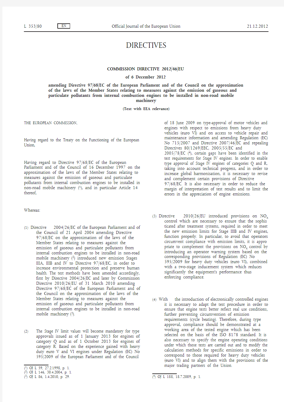
5.3.2. The low-level inducement system shall gradually reduce the maximum available engine torque across the
engine speed range by at least 25 per cent between the peak torque speed and the governor breakpoint as
shown in Figure 1. The rate of torque reduction shall be a minimum of 1 % per minute.
as
authority
approval
type
having
or
same
the
are
the
5.3.3. Other
measures
inducement
to
demonstrated
that
greater level of severity may be used.
Figure 1
Low-level inducement torque reduction scheme
5.4. Severe inducement system
5.4.1. The severe inducement system shall be activated after any of the conditions specified in paragraphs
2.3.3.2, 6.3.2, 7.3.2, 8.4.2, and 9.4.2 has occurred. 5.4.2.
The severe inducement system shall reduce the machine’s utility to a level that is sufficiently onerous as to cause the operator to remedy any problems related to Sections 6 to 9. The following strategies are acceptable:
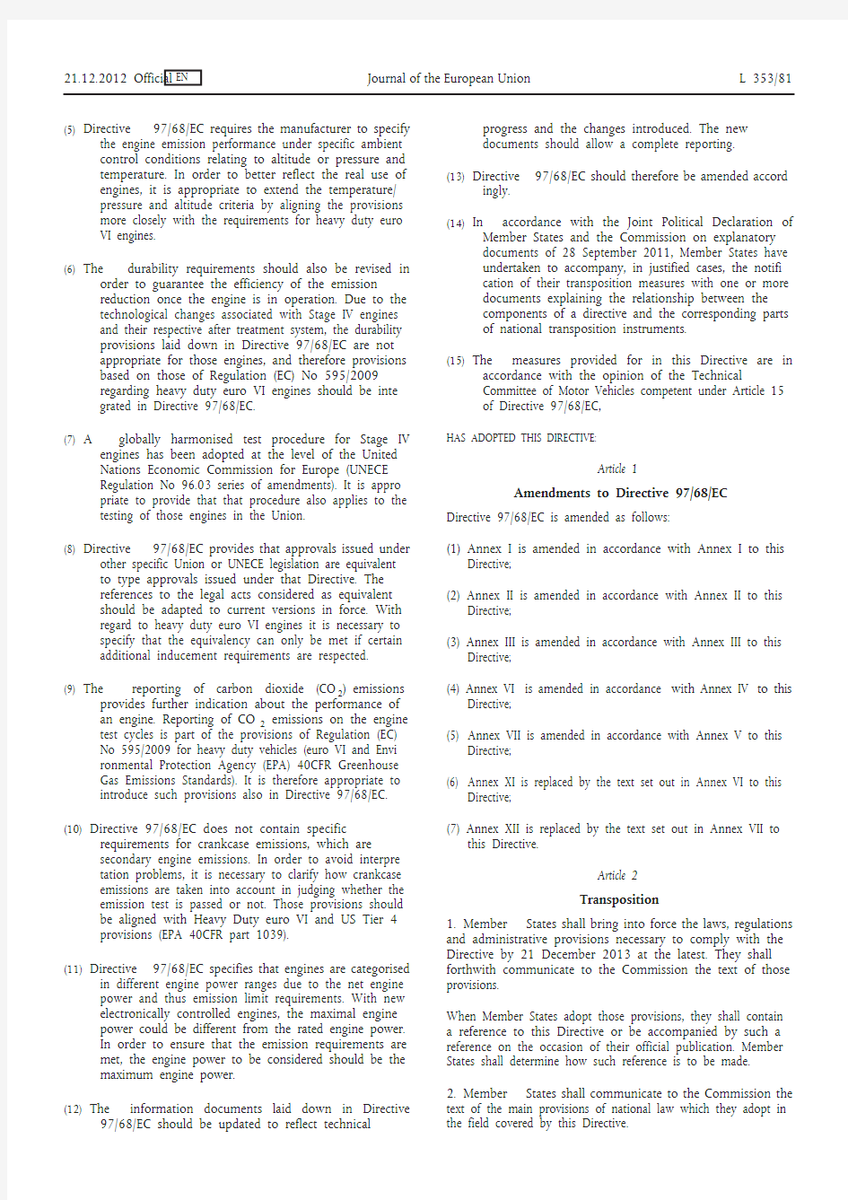
5.4.2.1.
Engine torque between the peak torque speed and the governor breakpoint shall be gradually reduced from the low-level inducement torque in Figure 1 by a minimum of 1 per cent per minute to 50 per cent of maximum torque or lower and engine speed shall be gradually reduced to 60 per cent of rated speed or lower within the same time period as the torque reduction, as shown in Figure 2.
Figure 2
Severe inducement torque reduction scheme
5.4.2.2. Other inducement measures that are demonstrated to the type approval authority as having the same or
greater level of severity may be used. 5.5.
In order to account for safety concerns and to allow for self-healing diagnostics, use of an inducement override function for releasing full engine power is permitted provided it — is active for no longer than 30 minutes, and
— is limited to three activations during each period that the operator inducement system is active.
5.6. The operator inducement system shall be deactivated when the conditions for its activation have ceased to
exist. The operator inducement system shall not be automatically deactivated without the reason for its activation having been remedied. 5.7. Details of the operator inducement system activation and deactivation procedures are described in
Section 11. 5.8.
As part of the application for type-approval under this Directive, the manufacturer shall demonstrate the operation of the operator inducement system, as specified in Section 11.
6. Reagent availability 6.1. Reagent level indicator
The machine shall include an indicator that clearly informs the operator of the level of reagent in the
reagent storage tank. The minimum acceptable performance level for the reagent indicator is that it shall continuously indicate the reagent level whilst the operator warning system referred to in paragraph 4 is activated. The reagent indicator may be in the form of an analogue or digital display, and may show the level as a proportion of the full tank capacity, the amount of remaining reagent, or the estimated operating hours remaining.
6.2. Activation of the operator warning system 6.2.1.
The operator warning system specified in paragraph 4 shall be activated when the level of reagent goes
below 10 % of the capacity of the reagent tank or a higher percentage at the choice of the manufacturer.
6.2.2. The warning provided shall be sufficiently clear, in conjunction with the reagent indicator, for the
operator to understand that the reagent level is low. When the warning system includes a message display system, the visual warning shall display a message indicating a low level of reagent (for example “urea level low”, “AdBlue level low”, or “reagent low”). 6.2.3.
The operator warning system does not initially need to be continuously activated (for example a message does not need to be continuously displayed), however activation shall escalate in intensity so that it becomes continuous as the level of the reagent approaches empty and the point where the operator inducement system will come into effect is approached (for example frequency at which a lamp flashes). It shall culminate in an operator notification at a level that is at the choice of the manufacturer, but sufficiently more noticeable at the point where the operator inducement system in paragraph 6.3 comes into effect than when it was first activated.
6.2.4.
The continuous warning shall not be easily disabled or ignored. When the warning system includes a message display system, an explicit message shall be displayed (for example “fill up urea”, “fill up AdBlue”, or “fill up reagent”). The continuous warning may be temporarily interrupted by other warning signals providing important safety related messages.
6.2.5.
It shall not be possible to turn off the operating warning system until the reagent has been replenished to a level not requiring its activation.
6.3. Activation of the operator inducement system
6.3.1. The low-level inducement system described in paragraph 5.3 shall be activated if the reagent tank level
goes below 2,5 % of its nominally full capacity or a higher percentage at the choice of the manufacturer. 6.3.2. The severe inducement system described in paragraph 5.4 shall be activated if the reagent tank is empty
(that is, when the dosing system is unable to draw further reagent from the tank) or at any level below 2,5 % of its nominally full capacity at the discretion of the manufacturer. 6.3.3.
Except to the extent permitted by paragraph 5.5, it shall not be possible to turn off the low-level or severe inducement system until the reagent has been replenished to a level not requiring their respective activation.
7. Reagent quality monitoring 7.1.
The engine or machine shall include a means of determining the presence of an incorrect reagent on
board a machine.
7.1.1. The manufacturer shall specify a minimum acceptable reagent concentration CDmin, which results in
tailpipe NO x emissions not exceeding a threshold of 0,9 g/kWh. 7.1.1.1. The correct value of CDmin shall be demonstrated during type approval by the procedure defined in
Section 12 and recorded in the extended documentation package as specified in Section 8 of Annex I. 7.1.2.
Any reagent concentration lower than CDmin shall be detected and be regarded, for the purpose of Section 7.1, as being incorrect reagent.
7.1.3.
A specific counter (“the reagent quality counter”) shall be attributed to the reagent quality. The reagent quality counter shall count the number of engine operating hours with an incorrect reagent.
7.1.3.1.
Optionally, the manufacturer may group the reagent quality failure together with one or more of the failures listed in Sections 8 and 9 into a single counter.
7.1.4.
Details of the reagent quality counter activation and deactivation criteria and mechanisms are described in Section 11.
7.2. Activation of the operator warning system
When the monitoring system confirms that the reagent quality is incorrect, the operator warning system
described in paragraph 4 shall be activated. When the warning system includes a message display system, it shall display a message indicating the reason of the warning (for example “incorrect urea detected”, “incorrect AdBlue detected”, or “incorrect reagent detected”).
7.3. Activation of the operator inducement system
7.3.1. The low-level inducement system described in paragraph 5.3 shall be activated if the reagent quality is not
rectified within a maximum of 10 engine operating hours after the activation of the operator warning system described in paragraph 7.2. 7.3.2. The severe inducement system described in paragraph 5.4 shall be activated if the reagent quality is not
rectified within a maximum of 20 engine operating hours after the activation of the operator warning system in described paragraph 7.2. 7.3.3.
The number of hours prior to activation of the inducement systems shall be reduced in case of a repetitive occurrence of the malfunction according to the mechanism described in Section 11.
8. Reagent dosing activity 8.1.
The engine shall include a means of determining interruption of dosing.
8.2. Reagent dosing activity counter
8.2.1. A specific counter shall be attributed to the dosing activity (the “dosing activity counter”). The counter
shall count the number of engine operating hours which occur with an interruption of the reagent dosing activity. This is not required where such interruption is demanded by the engine ECU because the machine operating conditions are such that the machine’s emission performance does not require reagent dosing. 8.2.1.1. Optionally, the manufacturer may group the reagent dosing failure together with one or more of the
failures listed in Sections 7 and 9 into a single counter. 8.2.2. Details of the reagent dosing activity counter activation and deactivation criteria and mechanisms are
described in Section 11. 8.3. Activation of the operator warning system
The operator warning system described in paragraph 4 shall be activated in the case of interruption of
dosing which sets the dosing activity counter in accordance with paragraph 8.2.1. When the warning system includes a message display system, it shall display a message indicating the reason of the warning (e.g. “urea dosing malfunction”, “AdBlue dosing malfunction”, or “reagent dosing malfunction”).
8.4. Activation of the operator inducement system
8.4.1. The low-level inducement system described in paragraph 5.3 shall be activated if an interruption in
reagent dosing is not rectified within a maximum of 10 engine operating hours after the activation of the operator warning system in paragraph 8.3. 8.4.2. The severe inducement system described in paragraph 5.4 shall be activated if an interruption in reagent
dosing is not rectified within a maximum of 20 engine operating hours after the activation of the operator warning system in paragraph 8.3. 8.4.3.
The number of hours prior to activation of the inducement systems shall be reduced in case of a repetitive occurrence of the malfunction according to the mechanism described in Section 11.
9. Monitoring failures that may be attributed to tampering 9.1.
In addition to the level of reagent in the reagent tank, the reagent quality, and the interruption of dosing,
the following failures shall be monitored because they may be attributed to tampering: (i) impeded EGR valve;
(ii) failures of the NO x Control Diagnostic (NCD) system, as described in paragraph 9.2.1.
9.2. Monitoring requirements
9.2.1. The NO x Control Diagnostic (NCD) system shall be monitored for electrical failures and for removal or
deactivation of any sensor that prevents it from diagnosing any other failures mentioned in paragraphs 6 to 8 (component monitoring).
A non-exhaustive list of sensors that affect the diagnostic capability are those directly measuring NO x concentration, urea quality sensors, ambient sensors and sensors used for monitoring reagent dosing activity, reagent level, or reagent consumption.
9.2.2. EGR valve counter 9.2.2.1.
A specific counter shall be attributed to an impeded EGR valve. The EGR valve counter shall count the
number of engine operating hours when the DTC associated to an impeded EGR valve is confirmed to be active.
9.2.2.1.1. Optionally, the manufacturer may group the impeded EGR valve failure together with one or more of the
failures listed in Sections 7, 8 and 9.2.3 into a single counter.
9.2.2.2. Details of the EGR valve counter activation and deactivation criteria and mechanisms are described in
Section 11.
counter(s)
9.2.3. NCD
system
failures
monitoring
considered
(ii).
the
9.1
paragraph
in
to
of
specific
9.2.3.1. A
shall
counter
each
attributed
be
The NCD system counters shall count the number of engine operating hours when the DTC associated to
a malfunction of the NCD system is confirmed to be active. Grouping of several faults into a single
counter is permitted.
9.2.3.1.1. Optionally, the manufacturer may group the NCD system failure together with one or more of the failures
listed in Sections 7, 8 and 9.2.2 into a single counter.
and
criteria
mechanisms
are
in 9.2.3.2. Details
deactivation
described of
and
NCD
the
counter(s)
activation
system
Section 11.
warning
operator
system
of
the
9.3. Activation
The operator warning system described in paragraph 4 shall be activated in case any of the failures
specified in paragraph 9.1 occur, and shall indicate that an urgent repair is required. When the warning
system includes a message display system, it shall display a message indicating the reason of the warning
(for example “reagent dosing valve disconnected”, or “critical emission failure”).
inducement
system
operator
the
9.4. Activation
of
if
be
a
specified
in
shall
failure
activated
inducement
low-level
9.4.1. The
system
described
paragraph
in
5.3
paragraph 9.1 is not rectified within a maximum of 36 engine operating hours after the activation of the
operator warning system in paragraph 9.3.
activated
be
if
failure
in
specified
a
shall
inducement
5.4
9.4.2. The
system
severe
paragraph
in
described
paragraph 9.1 is not rectified within a maximum of 100 engine operating hours after the activation of
the operator warning system in paragraph 9.3.
9.4.3. The number of hours prior to activation of the inducement systems shall be reduced in case of a repetitive
occurrence of the malfunction according to the mechanism described in Section 11.
9.5. As an alternative to the requirements in paragraph 9.2, the manufacturer may use a NO x sensor located in
the exhaust gas. In this case,
— the NO x value shall not exceed a threshold of 0,9 g/kWh,
— use of a single failure “high NO x— root cause unknown” may be used,
— Section 9.4.1 shall read “within 10 engine hours”,
— Section 9.4.2 shall read “within 20 engine hours”.
requirements
10. Demonstration
10.1. General
The compliance to the requirements of this Annex shall be demonstrated during type-approval by
performing, as illustrated in Table 1 and specified in this section:
(a) a demonstration of the warning system activation;
(b) a demonstration of the low level inducement system activation, if applicable;
(c) a demonstration of the severe inducement system activation.
Table 1
Illustration of the content of the demonstration process according to the provisions in Sections
10.3 and 10.4 of this Appendix
10.2. Engine families And NCD engine families
The compliance of an engine family or an NCD engine family with the requirements of this Section 10
may be demonstrated by testing one of the members of the considered family, provided the manufacturer demonstrates to the approval authority that the monitoring systems necessary for complying with the requirements of this Annex are similar within the family.
10.2.1.
The demonstration that the monitoring systems for other members of the NCD family are similar may be performed by presenting to the approval authorities such elements as algorithms, functional analyses, etc.
10.2.2. The test engine is selected by the manufacturer in agreement with the approval authority. It may or may
not be the parent engine of the considered family. 10.2.3.
In the case where engines of an engine family belong to an NCD engine family that has already been type-approved according to paragraph 10.2.1 (Figure 3), the compliance of that engine family is deemed to be demonstrated without further testing, provided the manufacturer demonstrates to the authority that the monitoring systems necessary for complying with the requirements of this Annex are similar within the considered engine and NCD engine families.
Figure 3
Previously demonstrated conformity of an NCD engine family
10.3. Demonstration of the warning system activation
10.3.1. The compliance of the warning system activation shall be demonstrated by performing two tests: lack of
reagent, and one failure category considered in Section 7 to 9 of this Annex. 10.3.2. Selection of the failures to be tested
10.3.2.1. For the purpose of demonstrating the activation of the warning system in case of a wrong reagent quality,
a reagent shall be selected with a dilution of the active ingredient at least as dilute as that communicated by the manufacturer according to the requirements of Section 7 of this Annex
Conformity of Engine family 1is considered as demonstrated
Conformity of NCD engine family 1
has been demonstrated for Engine family 2
Engine family 1
Engine family 2
NCD engine family 1
10.3.2.2. For the purpose of demonstrating the activation of the warning system in case of failures that may be
attributed to tampering, and are defined in Section 9 of this Annex the selection shall be performed
according to the following requirements:
10.3.2.2.1. The manufacturer shall provide the approval authority with a list of such potential failures.
10.3.2.2.2. The failure to be considered in the test shall be selected by the approval authority from this list referred to
in Section 10.3.2.2.1.
10.3.3. Demonstration
10.3.3.1. For the purpose of this demonstration, a separate test shall be performed for each of the failures
considered in Section 10.3.1.
10.3.3.2. During a test, no failure shall be present other than the one addressed by the test.
10.3.3.3. Prior to starting a test, all DTC shall have been erased.
10.3.3.4. At the request of the manufacturer, and with the agreement of the approval authority, the failures subject
to testing may be simulated.
10.3.3.5. Detection of failures other than lack of reagent
For failures other than lack of reagent, once the failure installed or simulated, the detection of that failure
shall be performed as follows:
10.3.3.5.1. The NCD system shall respond to the introduction of a failure selected as appropriate by the type
approval authority in accordance to the provisions of this Appendix. This is considered to be demon-
strated if activation occurs within two consecutive NCD test-cycles according to paragraph 10.3.3.7 of
this Appendix.
When it has been specified in the monitoring description and agreed by the Approval Authority that a
specific monitor needs more than two NCD test-cycles to complete its monitoring, the number of NCD
test-cycles may be increased to three NCD test-cycles.
Each individual NCD test-cycle in the demonstration test may be separated by an engine shut-off. The
time until the next start-up shall take into consideration any monitoring that may occur after engine shut-
off and any necessary condition that must exist for monitoring to occur at the next start-up.
10.3.3.5.2. The demonstration of the warning system activation is deemed to be accomplished if, at the end of each
demonstration test performed according to Section 10.3.2.1, the warning system has been properly
activated and the DTC for the selected failure has got the “confirmed and active” status.
10.3.3.6. Detection in case of lack of reagent
For the purpose of demonstrating the activation of the warning system in case of lack of reagent, the
engine system shall be operated over one or more NCD test cycles at the discretion of the manufacturer.
10.3.3.6.1. The demonstration shall start with a level of reagent in the tank to be agreed between the manufacturer
and the approval authority but representing not less than 10 per cent of the nominal capacity of the tank.
10.3.3.6.2. The warning system is deemed to have performed in the correct manner if the following conditions are
met simultaneously:
(a) the warning system has been activated with a reagent availability greater or equal to 10 per cent of
the capacity of the reagent tank, and
(b) the “continuous” warning system has been activated with a reagent availability greater or equal to the
value declared by the manufacturer according to the provisions of Section 6 of this Annex.
10.3.3.7. NCD test cycle
10.3.3.7.1. The NCD test cycle considered in this Section 10 for demonstrating the correct performance of the NCD
system is the hot NRTC cycle.
10.3.3.7.2. On request of the manufacturer and with approval of the Approval Authority, an alternative NCD test-
cycle can be used (e.g. the NRSC) for a specific monitor. The request shall contain elements (technical
considerations, simulation, test results, etc.) demonstrating:
(a) the requested test-cycle results in a monitor that will run in real world driving, and
(b) the applicable NCD test-cycle specified in paragraph 10.3.3.7.1 is shown to be less appropriate for the
considered monitoring.
10.3.4. The demonstration of the warning system activation is deemed to be accomplished if, at the end of each
demonstration test performed according to Section 10.3.3, the warning system has been properly
activated.
activation
system
inducement
10.4. Demonstration
of
the
tests
by
performed
engine
done
an
on
be
the
of
demonstration
10.4.1. The
inducement
system
shall
activation
test bench.
10.4.1.1. Any components or subsystems not physically mounted on the engine system, such as, but not limited to,
ambient temperature sensors, level sensors, and operator warning and information systems, that are
required in order to perform the demonstrations shall be connected to the engine system for that
purpose, or shall be simulated, to the satisfaction of the approval authority.
10.4.1.2. If the manufacturer chooses, and subject to the agreement of the approval authority, the demonstration
tests may be performed on a complete machine or machinery either by mounting the machine on a
suitable test bed or by running it on a test track under controlled conditions.
10.4.2. The test sequence shall demonstrate the activation of the inducement system in case of lack of reagent
and in case of one of the failures defined in Sections 7, 8, or 9 of this Annex.
of
demonstration:
this
purpose
the
10.4.3. For
(a) the approval authority shall select, in addition to the lack of reagent, one of the failures defined in
Sections 7, 8 or 9 of this Annex that has been previously used in the demonstration of the warning
system activation;
(b) the manufacturer shall, in agreement with the approval authority, be permitted to accelerate the test
by simulating the achievement of a certain number of operating hours;
(c) the achievement of the torque reduction required for low-level inducement may be demonstrated at
the same time as the general engine performance approval process performed in accordance with this
Directive. Separate torque measurement during the inducement system demonstration is not required
in this case;
(d) the severe inducement shall be demonstrated according to the requirements of Section 10.4.6 of this
Appendix.
10.4.4. The manufacturer shall, in addition, demonstrate the operation of the inducement system under those
failure conditions defined in Sections 7, 8 or 9 of this Annex which have not been chosen for use in
demonstration tests described in Sections 10.4.1 to 10.4.3.
These additional demonstrations may be performed by presentation to the approval authority of a
technical case using evidence such as algorithms, functional analyses, and the result of previous tests.
10.4.4.1. These additional demonstrations shall in particular demonstrate to the satisfaction of the approval
authority the inclusion of the correct torque reduction mechanism in the engine ECU.
level
inducement
system
10.4.5. Demonstration
low
test
of
the
10.4.5.1. This demonstration starts when the warning system or when appropriate “continuous” warning system
has been activated as a result of the detection of a failure selected by the approval authority.
10.4.5.2. When the system is being checked for its reaction to the case of lack of reagent in the tank, the engine
system shall be run until the reagent availability has reached a value of 2,5 per cent of the nominal full
capacity of the tank or the value declared by the manufacturer in accordance with Section 6.3.1 of this
Annex at which the low-level inducement system is intended to operate.
10.4.5.2.1. The manufacturer may, with the agreement of the approval authority, simulate continuous running by
extracting reagent from the tank, either whilst the engine is running or is stopped.
10.4.5.3. When the system is checked for its reaction in the case of a failure other than a lack of reagent in the
tank, the engine system shall be run for the relevant number of operating hours indicated in Table 3 of
this Appendix or, at the choice of the manufacturer, until the relevant counter has reached the value at
which the low-level inducement system is activated.
10.4.5.4. The demonstration of the low level inducement system shall be deemed to be accomplished if, at the end
of each demonstration test performed according to Sections 10.4.5.2 and 10.4.5.3, the manufacturer has
demonstrated to the approval authority that the engine ECU has activated the torque reduction mech-
anism.
severe
inducement
system
of
the
10.4.6. Demonstration
test
10.4.6.1. This demonstration shall start from a condition where the low-level inducement system has been
previously activated and may be performed as a continuation of the tests undertaken to demonstrate
the low-level inducement system.
10.4.6.2. When the system is checked for its reaction in the case of lack of reagent in the tank, the engine system
shall be run until the reagent tank is empty, or has reached the level below 2,5 per cent of the nominal
full capacity of the tank at which the manufacturer has declared to activate the severe inducement system.
10.4.6.2.1. The manufacturer may, with the agreement of the approval authority, simulate continuous running by
extracting reagent from the tank, either whilst the engine is running or is stopped.
10.4.6.3. When the system is checked for its reaction in the case of a failure that is not a lack of reagent in the
tank, the engine system shall then be run for the relevant number of operating hours indicated in Table 3
of this Appendix or, at the choice of the manufacturer, until the relevant counter has reached the value at
which the severe inducement system is activated.
10.4.6.4. The demonstration of the severe inducement system shall be deemed to be accomplished if, at the end of
each demonstration test performed according to paragraphs 10.4.6.2 and 10.4.6.3, the manufacturer has
demonstrated to the type-approval authority that the severe inducement mechanism considered in this
Annex has been activated.
10.4.7. Alternatively, if the manufacturer chooses, and subject to the agreement of the approval authority, the
demonstration of the inducement mechanisms may be performed on a complete machine in accordance
with the requirements of Section 5.4, either by mounting the machine on a suitable test bed or by
running it on a test track under controlled conditions.
10.4.7.1. The machine shall be operated until the counter associated with the selected failure has reached the
relevant number of operating hours indicated in Table 3 of this Appendix or, as appropriate, until either
the reagent tank is empty or, has reached the level below 2,5 per cent of the nominal full capacity of the
tank at which the manufacturer has chosen to activate the severe inducement system.
and
activation
mechanisms
inducement
deactivation
operator
11. Description
of
the
warning
and
11.1. To complement the requirements specified in this Annex concerning the warning and inducement
activation and deactivation mechanisms, this Section 11 specifies the technical requirements for an
implementation of those activation and deactivation mechanisms.
warning
system
of
the
11.2. Activation
and
deactivation
mechanisms
11.2.1. The operator warning system shall be activated when the diagnostic trouble code (DTC) associated with a
NCM justifying its activation has the status defined in Table 2 of this Appendix.
Table 2
Activation of the operator warning system
11.2.2. The operator warning system shall be deactivated when the diagnostic system concludes that the
malfunction relevant to that warning is no longer present or when the information including DTCs
relative to the failures justifying its activation is erased by a scan tool.
11.2.2.1. Requirements for erasing “NO x control information”
11.2.2.1.1. Erasing/resetting “NO x control information” by a scan-tool
On request of the scan tool, the following data shall be erased or reset to the value specified in this
Appendix from the computer memory (see Table 3).
Table 3
Erasing/resetting “NO x control information” by a scan-tool
11.2.2.1.2. NO x control information shall not be erased by disconnection of the machine’s battery(s).
11.2.2.1.3. The erasing of “NO x control information” shall only be possible under “engine-off” conditions.
11.2.2.1.4. When “NO x control information” including DTCs are erased, any counter reading associated with these
failures and which is specified in this Annex shall not be erased, but reset to the value specified in the
appropriate section of this Annex.
11.3. Activation
inducement
system
the
operator
and
deactivation
mechanism
of
11.3.1. The operator inducement system shall be activated when the warning system is active and the counter
relevant to the type of NCM justifying its activation has reached the value specified in Table 4 of this
Appendix.
11.3.2. The operator inducement system shall be deactivated when the system no longer detects a malfunction
justifying its activation, or if the information including the DTCs relative to the NCMs justifying its
activation has been erased by a scan tool or maintenance tool.
activated
immediately
or
deactivated
appro-
as
be
shall
warning
operator
and
inducement
systems
11.3.3. The
priate according to the provisions of Section 6 of this Annex after assessment of the reagent quantity in
the reagent tank. In that case, the activation or deactivation mechanisms shall not depend upon the status
of any associated DTC.
mechanism
11.4. Counter
11.4.1. General
11.4.1.1. To comply with the requirements of this Annex, the system shall contain at least four counters to record
the number of hours during which the engine has been operated while the system has detected any of the
following:
(a) an incorrect reagent quality;
(b) an interruption of reagent dosing activity;
(c) an impeded EGR valve;
(d) a failure of the NCD system according to Section 9.1(ii) of this Annex.
11.4.1.1.1. Optionally, the manufacturer may use one or more counters for grouping the failures indicated in Section
11.4.1.1.
11.4.1.2. Each of the counters shall count up to the maximum value provided in a 2 byte counter with 1 hour
resolution and hold that value unless the conditions allowing the counter to be reset to zero are met.
11.4.1.3. A manufacturer may use a single or multiple NCD system counters. A single counter may accumulate the
number of hours of two or more different malfunctions relevant to that type of counter, none of them
having reached the time the single counter indicates.
11.4.1.3.1. When the manufacturer decides to use multiple NCD system counters, the system shall be capable of
assigning a specific monitoring system counter to each malfunction relevant according to this Annex to
that type of counters.
11.4.2. Principle
counters
mechanism
of
11.4.2.1. Each of the counters shall operate as follows:
11.4.2.1.1. If starting from zero, the counter shall begin counting as soon as a malfunction relevant to that counter is
detected and the corresponding diagnostic trouble code (DTC) has the status defined in Table 2.
11.4.2.1.2. In case of repeated failures, one of the following provisions shall apply at the choice of the manufacturer.
(i) If a single monitoring event occurs and the malfunction that originally activated the counter is no
longer detected or if the failure has been erased by a scan tool or a maintenance tool, the counter
shall halt and hold its current value. If the counter stops counting when the severe inducement system
is active, the counter shall be kept frozen at the value defined in Table 4 of this Appendix or a value
of greater than or equal to the counter value for severe inducement minus 30 minutes.
(ii) The counter shall be kept frozen at the value defined in Table 4 of this Appendix or a value greater than or equal to the counter value for severe inducement minus 30 minutes.
11.4.2.1.3. In the case of a single monitoring system counter, that counter shall continue counting if a NCM relevant
to that counter has been detected and its corresponding Diagnostic trouble code (DTC) has the status
“confirmed and active”. It shall halt and hold one of the values specified in Section 11.4.2.1.2, if no NCM
that would justify the counter activation is detected or if all the failures relevant to that counter have been
erased by a scan tool or a maintenance tool.
Table 4
Counters and inducement
国六排放标准China VI vehicle emission standards Sales and registrations of new vehicles in regions including Beijing, Shanghai, Tianjin, Hebei province and Guangdong province now have to comply with the "China VI" vehicle emission standards, which is believed to be one of the world's strictest rules on automobile pollutants. 北京、上海、天津、河北、广东等地区销售和登记注册的新车都需符合国六排放标准,该标准被认为是全世界最严格的机动车污染物排放标准之一。 【知识点】 国六排放标准(China VI vehicle emission standards)全称为“国家第六阶段机动车污染物排放标准(China's stage 6 vehicle emission standards)”,分为对轻型车以及重型柴油车两类标准,全称分别为《轻型汽车污染物排放限值及测量方法(中国第六阶段)(Stage 6 Limits and Measurement Methods for Emissions from Light-Duty Vehicles)》,以及重型柴油车污染物排放限值及测量方法(中国第六阶段)(Stage 6 Limits and Measurement Methods for Emissions from heavy-duty diesel vehicles)》。由环境保护部、国家质检总局分别于2016年12月23日、2018年6月22日发布。其中,轻型汽车(light-duty vehicles)指包括轻型汽油车(light-duty gasoline vehicles)、轻型燃气车(light-duty natural gas vehicles)、轻型柴油车(light-duty diesel vehicles)和轻型两
国六排放标准范文 目录 FTP排放标准 LEVI FTP排放标准[g/mile]: 注: a) 括号中的值为PC和LDT1的100,000英里标准及MDV-4的120,000英里标准,其他值 为50,000英里标准。 b) 只适用于柴油机 LEVII FTP排放标准[g/mile] a) 括号中的值为120,000英里标准,其他值为50,000英里标准 b) 只适用于柴油机 LEV II的执行进度表(百分比列表) 对于FTP测试,LEV II方案包括所有LVW>3750 lbs到LDT2类别中GVWR为8500lbs(包括LEVI中MDV2-MDV4类别的车辆)的LDT 类别的车辆。 各年进度各车型的百[%] 分比不能叠加 年(LDT)的NOx排放目标0.07g/mile,加州方案的目标是持续 减少NMOG的平均排放标准。 CO低温标准 PC/LDT1类别的车辆在20°F(大约零下6.7°C)时CO的排放不得超过10.0g/mile,所有其他类别直到GVW为8500lbs的车辆不得 超过12.5g/mile。
50°F标准 另外,CO和 NOx在50°F(10°C)时的排放不得超过已生效的FTP尾气排放标准。但天然气和柴油机车辆除外。 ZEV执行规定(Mandate) ZEF执行规定最初在加州制订,随后被马萨诸塞州、纽约、佛蒙特州及新泽西州所采用。ZEF法规被评审并修改过数次,最近一次修改于xx年2月25号批准通过并在xx年3月26日生效。 修改后的版本规定包括从xx年开始大产量制造商(每年在加州销售的PC、LDT和MDV车辆之和的数量为60,000及以上者),其生产的PC和LDT1类别车辆的至少10%必须替代为ZEV车辆,而且该百分比将逐年递增,2018年达到16%。 从xx年到xx年,LDT2类别的车要求ZEV的比例为: PZEV规定 基本PZEV补贴 车辆要得到0.2的PZEV补贴,必须在150,000英里里程时满足以下条件:-SULEV尾气排放标准-零蒸发排放标准-在线诊断要求 大产量制造商可以用PZEV车辆来代替60%的ZEV车辆组成百分比要求,但剩下的部分则必须由50%真正的ZEV车辆和50%的先进PZEV(AT PZEV)车辆组成,所谓AT PZEV是指满足PZEV的标准同时具有先进技术特性的车辆(如混合动力、G等)。做为一个选项,大
中国-柴油机欧4排放的基本技术路线 及相关问题 发动机排放污染物主要有HC(碳氢化合物)、NOx(氮氧合物)、CO(一氧化碳)、PM(微粒)等,它们主要通过车辆排气管排放,将近45%的HC和极小数的其它污染物质则由曲轴箱和燃油系统排放。 在上述汽车排放污染物中,CO是燃油不完全燃烧的产物,对人的健康危害较大。HC主要是燃油蒸发及不完全燃烧的产物,由200多种不同的成份构成,含有致癌物质。NOx是在燃烧室高温高压条件下,由氮和氧化合而成,排放到大气后变成NO2(二氧化碳),其毒性很强,对人及植物生长均有不良影响,是形成酸雨及光化学烟雾的主要物质之一。PM主要成份是碳烟,上面附有大量化学物质,包含致癌物质,吸入人体后会在肺部长期停留。 对于大功率柴油机而言: 基本上有两条路线 1 通过EGR把NOX 降下来, 然后通过颗粒捕集器或颗粒氧化器等后处理技术把PM降到欧4水平; 2 通过燃烧系统优化(主要采用高压喷射+合理的燃烧组织)把颗粒降下来,但同时允许NOX升高,然后,在排气后处理系统中,通过SCR催化器把NOX降到欧4水平.但在现在的中国,使用DPF以及SCR都存在很多客观限制因素,比如油品\ 基础设施等问题. 对于小功率柴油机而言: 比较现实的技术方案是: 直喷+增压中冷+冷却EGR+氧化催化器+电控燃油喷射系统(最好是共轨); 目前存在的问题 1、SCR:在商用车上应用的难点是加尿素问题,除非在国家政策的支持下加尿素站就像加油站一样普遍。在乘用车上应用还有安装空间问题,以及乘用车大部分使用工况排气温度对于SCR来说过低。低温结晶如何解决,在东北根本不能用,-11度就结晶;成本非常高,在国外一套合格的SCR系统要6000美圆,要防止NH3的逸出,需要进行精确的标定匹配,要加装氧化催化器以除去NH3,但有氧化催化器对硫又很敏感。 2、DPF:燃油的含硫量是应用的大问题,如果中国生产不了<50ppm的柴油,DPF的应用是空谈。DPF在中国的应用还存在发动机生产一致性问题,因为DPF 再生标定还不能完全闭环,如果发动机一致性差异大可能会发生堵塞或烧毁。当然发动机只采用EGR+DOC也有达到国4排放的可能的,方法是降低发动机功
欧洲III号排放标准- 1.何谓欧洲环保标准 有关环保的话题灸手可热,其中不可避免的涉及到欧洲环保标准,尤其以欧I、欧Ⅱ标准出现的频率最高,那什么是欧I、欧Ⅱ标准呢?以设计乘员数不超过6人包括司机,且最大总质量不超过2.5吨这类车辆为例,在1999年1月至2003年12月31日这个阶段,必须达到排放标准的限值为:一氧化碳不得超过3.16克/公里,碳氢化合物不得超过1.13克/公里,其中柴油车的颗粒物不得超过0.18克/公里,耐久性要求为5万公里,以上便是我们平常所提到的欧洲I号标准。到2004年1月1日后,这个标准又有所提高,汽油车一氧化碳不超过2.2克/公里,碳氢化合物不得超过0.5克/公里,柴油车一氧化碳不超过1.0克/公里,碳氢化合物不得超过0.7克/公里,颗粒物标准不得超过0.08克/公里,这便是我们所说的欧洲II号标准。如果仅考虑排放量,执行欧Ⅱ标准的机动车污染物排放量将比欧I标准减少30%到50%。而欧洲Ⅲ标准是目前欧洲、美国正在实施的真正意义上的低污染排放标准。据专家介绍,我国实行欧洲标准的影响:7辆执行欧Ⅱ标准的汽车,就相当于1辆化油器车的污染物排放量;14辆执行欧Ⅲ标准的汽车,才相当于1辆化油器车的污染物排放量。汽车排放从欧Ⅱ到欧Ⅲ,不是像欧Ⅰ到欧Ⅱ那样简单,提升幅度大了很多。欧Ⅲ排放标准比欧Ⅱ在NEDC和燃油蒸发排放检测项目上的内容有所变化,欧Ⅲ标准中增加了低温HC/CO排放检测、车载诊断系统检测和在用车排放检测。从欧Ⅱ到欧Ⅲ执行不同的排放控制技术,欧Ⅱ排放标准只要求三元催化器及发动机改进措施两项,而欧Ⅲ排放则还包括改进的催化转化器涂层、催化剂加热及二次空气喷射。可以看出,欧Ⅲ排放控制技术要比欧Ⅱ复杂和困难得多。欧洲汽车排放标准见表1。 表1欧洲汽车排放标准
国六轻型车排放标准介绍 2017‐11‐10
国六标准历程 2015.1 标准启动2016.6 公开征求 意见 2016.10.3 WTO/TBT 通报 2016.10.18 部常务会 审议通过 2016.12 发布
国六标准控制重点 ?采用燃料中立的更严格的限值 ?蒸发排放控制要求 ?低温下的污染物排放 ?实际行驶状态下的排放控制(RDE) ?OBD要求 ?温室气体协同控制
国6标准定位 创新 国六排放标准 延续 欧盟排放标准 协调 全球技术法规 融合 美国排放标准
国6标准概要 5 国6排放标准 工况排放(WLTC,L+M+H+ExH): ◆燃油中性,不区分汽柴油 1、CN6a: EU6C限值(CO;700mg/km) 2、CN6b: PN不变, PM加严1/3, 气体污染物加严50% 蒸发排放 1、密闭室蒸发排放(加严测试规程)–LEV II 2、加油蒸发排放(ORVR) -LEV III (分别补充了耐久性劣化因子规定。) 实施日期:2020-7-1(6a) 2023-7-1(6b ) 适用范围:GVW≤3500kg M1,M2,N1, N2 -7度低温排放(WLTC 低速和中速段): CO,THC:相当于国5的2/3; 新增NOx限值0.25g/km 耐久性:16万公里 规定了乘法老化因子和加法老化因子 OBD:参考了CARB OBD II 2013版,OBD 阈值统一采用EU6-2汽油车限值,将NMHC +NOx 进行组合。 在用车符合性: 可检查排气污染、OBD系统、 蒸发污染物以及加油污染的符合性要求 生产一致性检查: 可检查I,II,III,IV,VI,VII 和OBD系统 RDE :参考EU 的RDE 的PEMS 测试要求,采用 移动平均窗口法评价。2023年强制引入NTE 限值要求(PN-CF 值为2.1;NOx-CF 值为2.1)
欧洲排放标准 欧洲标准是由欧洲经济委员会(ECE)的排放法规和欧共体(EEC)的排放指令共同加以实现的,欧共体(EEC)即是现在的欧盟(EU)。排放法规由ECE参与国自愿认可,排放指令是EEC或EU参与国强制实施的。汽车排放的欧洲法规(指令)标准1992年前巳实施若干阶段,欧洲从1992年起开始实施欧Ⅰ(欧Ⅰ型式认证排放限值)、1996年起开始实施欧Ⅱ(欧Ⅱ型式认证和生产一致性排放限值)、2000年起开始实施欧Ⅲ(欧Ⅲ型式认证和生产一致性排放限值)、2005年起开始实施欧Ⅳ(欧Ⅳ型式认证和生产一致性排放限值)。 目前在我国新车常用的欧Ⅰ和欧Ⅱ标准等术语,是指当年EEC颁发的排放指令。例如适用于重型柴油车(质量大于3.5吨)的指令“EEC88/77”分为两个阶段实施,阶段A(即欧Ⅰ)适用于1993年10月以后注册的车辆;阶段B(即欧Ⅱ)适用于1995年10月以后注册的车辆。 汽车排放的欧洲法规(指令)标准的内容包括新开发车的型式认证试验和现生产车的生产一致性检查试验,从欧Ⅲ开始又增加了在用车的生产一致性检查。 汽车排放的欧洲法规(指令)标准的计量是以汽车发动机单位行驶距离的排污量(g/km)计算,因为这对研究汽车对环境的污染程度比较合理。同时,欧洲排放标准将汽车分为总质量不超过3500公斤(轻型车)和总质量超过3500公斤(重型车)两类。轻型车不管是汽油机或柴油机车,整车均在底盘测功机上进行试验。重型机由于车重,则用所装发动机在发动机台架上进行试验。 欧Ⅰ型式认证排放限值 车辆类别基准质量(RM)kg 限值g/km CO HC+NOx PM 第一类车全部 2.72 0.97(1.36) 0.14(0.20) 第二类车 1级RM≤1250 2.72 0.97(1.36) 0.14(0.20) 2级 1250<RM≤1700 5.17 1.40(1.96) 0.19(0.27) 3级 RM>1700 6.90 1.70(2.38) 0.25(0.35) 欧Ⅱ型式认证和生产一致性排放限值 车辆类别基准质量(RM)kg 限值g/km CO HC+NOx PM 汽油机柴油机汽油机非直喷柴油机直喷柴油机非直喷柴油机直喷柴油机 第一类车 _ 全部 2.2 1.0 0.5 0.7 0.9 0.08 0.10 第二类车 1级RM≤1250 2.2 1.0 0.5 0.7 0.9 0.08 0.10
DIRECTIVES COMMISSION DIRECTIVE 2012/46/EU of 6 December 2012 amending Directive 97/68/EC of the European Parliament and of the Council on the approximation of the laws of the Member States relating to measures against the emission of gaseous and particulate pollutants from internal combustion engines to be installed in non-road mobile machinery (Text with EEA relevance) THE EUROPEAN COMMISSION, Having regard to the Treaty on the Functioning of the European Union, Having regard to Directive 97/68/EC of the European Parliament and of the Council of 16 December 1997 on the approximation of the laws of the Member States relating to measures against the emission of gaseous and particulate pollutants from internal combustion engines to be installed in non-road mobile machinery ( 1 ), and in particular Article 14 thereof, Whereas: (1) Directive 2004/26/EC of the European Parliament and of the Council of 21 April 2004 amending Directive 97/68/EC on the approximation of the laws of the Member States relating to measures against the emission of gaseous and particulate pollutants from internal combustion engines to be installed in non-road mobile machinery ( 2 ) introduced new emission Stages IIIA, IIIB and IV to Directive 97/68/EC, in order to increase environmental protection and preserve human health. The test methods have been amended accordingly, first by Directive 2004/26/EC and later by Commission Directive 2010/26/EU of 31 March 2010 amending Directive 97/68/EC of the European Parliament and of the Council on the approximation of the laws of the Member States relating to measures against the emission of gaseous and particulate pollutants from internal combustion engines to be installed in non-road mobile machinery ( 3 ). (2) The Stage IV limit values will become mandatory for type approvals issued as of 1 January 2013 for engines of category Q and as of 1 October 2013 for engines of category R. Based on the experience gained with heavy duty euro V and VI engines under Regulation (EC) No 595/2009 of the European Parliament and of the Council of 18 June 2009 on type-approval of motor vehicles and engines with respect to emissions from heavy duty vehicles (euro VI) and on access to vehicle repair and maintenance information and amending Regulation (EC) No 715/2007 and Directive 2007/46/EC and repealing Directives 80/1269/EEC, 2005/55/EC and 2005/78/EC ( 4 ), certain gaps have been identified in the test requirements for Stage IV engines. In order to enable type approval of Stage IV engines of categories Q and R, taking into account technical progress, and in order to increase global harmonisation, it is necessary to revise and complement certain provisions of Directive 97/68/EC. It is also necessary in order to reduce the margin of interpretation of test results and to limit the errors in the appreciation of engine emissions. (3) Directive 2010/26/EU introduced provisions on NO x control which are necessary to ensure that the sophis - ticated after treatment systems, required in order to meet the new emission limits for Stage IIIB and IV engines, function properly. In particular, to avoid that operators circumvent compliance with emission limits, it is appro -priate to complement the provisions on NO x control by introducing an operator warning system based on the corresponding provisions of Regulation (EC) No 595/2009 for heavy duty vehicles (euro VI), combined with a two-stage inducement system which reduces significantly the equipment’s performance thus enforcing compliance. (4) With the introduction of electronically controlled engines it is necessary to adapt the test procedure in order to ensure that engine tests better reflect real use conditions, further preventing circumvention of emission requirements (cycle beating). Therefore, during type approval, compliance should be demonstrated at a working area of the tested engine which has been selected on the basis of the ISO 8178 standard. It is also necessary to specify the engine operating conditions under which those tests are carried out and to modify the calculation methods for specific emissions in order to correspond to those required for heavy duty vehicles (euro VI) and to align them with the provisions of the major trading partners of the Union. ( 1 ) OJ L 59, 27.2.1998, p. 1. ( 2 ) OJ L 146, 30.4.2004, p. 1. ( 3 ) OJ L 86, 1.4.2010, p. 29. ( 4 ) OJ L 188, 18.7.2009, p. 1.