OSPF实验过程详解(OSPF在NBMA上实现法)
- 格式:doc
- 大小:57.00 KB
- 文档页数:4

OSPF试验指南目标:对于OSPF的理解达到CCNA试验考察的要求。
需要掌握的知识点:OSPF的配置。
需要掌握的命令:IOS中OSPF配置的相关命令。
试验拓扑:图片附件: OSPF.gif (2006-4-21 09:45, 5.24 K)拓扑说明:R1:S1:10.10.12.1/24F0:192.168.135.1/24R2:S1:10.10.12.2/24F0:172.16.24.2/24R3:S1:10.10.34.3/24F0:192.168.135.3/24R4:S1:10.10.34.4/24F0:172.16.24.4/24R5:F0:192.168.135.5/24试验要求:1.路由器的IP地址如上所示。
每个路由器都有一个环回口,地址为X.X.X.X/32,X是你的路由器编号,例如: R1的环回口地址为1.1.1.1/32。
2.在所有路由器上开启OSPF路由协议。
3.配置结束后所有路由器都能看到所有网络的路由,并且能够ping通所有IP地址。
配置步骤:一.配置预配R1:Router>enable 进入特权模式Router#configure terminal 进入全局配置模式Router(config)#hostname R1 设置名字R1(config)#enable secret cisco 加密的R1(config)#no ip domain-lookup 关闭自动域名解析R1(config)#line console 0 进入线路con口R1(config-line)#password cisco 设置登陆密码R1(config-line)#login 启用密码R1(config-line)#logging synchronous 关闭同步日志R1(config-line)#exec-timeout 0 0从 con登陆永不超时(试验环境下)R1(config-line)#exitR1 (config)#line vty 0 4 telnet 远程登陆线路口R1 (config-line)#password ciscoR1 (config-line)#loginR1 (config-line)#logging synchronousR1 (config-line)#exec-timeout 0 0R1 (config-line)#exitR2:Router>enable 进入特权模式Router#configure terminal 进入全局配置模式Router(config)#hostname R1 设置名字R2(config)#enable secret cisco 加密的R2(config)#no ip domain-lookup 关闭自动域名解析R2(config)#line console 0 进入线路con口R2(config-line)#password cisco 设置登陆密码R2(config-line)#login 启用密码R2(config-line)#logging synchronous 关闭同步日志R2(config-line)#exec-timeout 0 0从 con登陆永不超时(试验环境下)R2(config-line)#exitR2 (config)#line vty 0 4 telnet 远程登陆线路口R2 (config-line)#password ciscoR2 (config-line)#loginR2 (config-line)#logging synchronousR2 (config-line)#exec-timeout 0 0R2 (config-line)#exitRouter>enable 进入特权模式Router#configure terminal 进入全局配置模式Router(config)#hostname R1 设置名字R3(config)#enable secret cisco 加密的R3(config)#no ip domain-lookup 关闭自动域名解析R3(config)#line console 0 进入线路con口R3(config-line)#password cisco 设置登陆密码R3(config-line)#login 启用密码R3(config-line)#logging synchronous 关闭同步日志R3(config-line)#exec-timeout 0 0从 con登陆永不超时(试验环境下)R3(config-line)#exitR3 (config)#line vty 0 4 telnet 远程登陆线路口R3 (config-line)#password ciscoR3 (config-line)#loginR3 (config-line)#logging synchronousR3 (config-line)#exec-timeout 0 0R3 (config-line)#exitR4:Router>enable 进入特权模式Router#configure terminal 进入全局配置模式Router(config)#hostname R1 设置名字R4(config)#enable secret cisco 加密的R4(config)#no ip domain-lookup 关闭自动域名解析R4(config)#line console 0 进入线路con口R4(config-line)#password cisco 设置登陆密码R4(config-line)#login 启用密码R4(config-line)#logging synchronous 关闭同步日志R4(config-line)#exec-timeout 0 0从 con登陆永不超时(试验环境下)R4(config-line)#exitR4 (config)#line vty 0 4 telnet 远程登陆线路口R4 (config-line)#password ciscoR4 (config-line)#loginR4 (config-line)#logging synchronousR4 (config-line)#exec-timeout 0 0R4 (config-line)#exitRouter>enable 进入特权模式Router#configure terminal 进入全局配置模式Router(config)#hostname R1 设置名字R5(config)#enable secret cisco 加密的R5(config)#no ip domain-lookup 关闭自动域名解析R5(config)#line console 0 进入线路con口R5(config-line)#password cisco 设置登陆密码R5(config-line)#login 启用密码R5(config-line)#logging synchronous 关闭同步日志R5(config-line)#exec-timeout 0 0从 con登陆永不超时(试验环境下)R5(config-line)#exitR5 (config)#line vty 0 4 telnet 远程登陆线路口R5 (config-line)#password ciscoR5 (config-line)#loginR5 (config-line)#logging synchronousR5 (config-line)#exec-timeout 0 0R5 (config-line)#exitSwitch0Switch>enable 用户模式到特权模式Switch#configure terminal 特权模式到全局配置模式Switch(config)#hostname Switch0 设置名字Switch0(config)#enable secret cisco 加密的Switch0(config)#no ip domain-lookup 关闭自动域名解析Switch0(config)#line console 0 进入线路console口Switch0(config-line)#password cisco 设置登陆密码Switch0(config-line)#login 启用密码Switch0(config-line)#logging synchronous 关闭同步日志Switch0(config-line)#exec-timeout 0 0 从 console登陆永不超时(试验环境下)Switch0(config-line)#exit 退出Switch0(config)#line vty 0 4 telnet 远程登陆线路口Switch0(config-line)#password ciscoSwitch0(config-line)#loginSwitch0(config-line)#logging synchronousSwitch0(config-line)#exec-timeout 0 0Switch0(config-line)#exit二、配置各接口IP地址R1:R1(config)#interface fastEthernet 0/0 以太网接口R1(config-if)#ip address 192.168.135.1 255.255.255.0 R1(config-if)#no shutdownR1(config-if)#exitR1(config)#interface serial 0/1/0 串行接口R1(config-if)#ip address 10.10.12.1 255.255.255.0R1(config-if)#clock rate 64000R1(config-if)#no shutdownR1(config-if)#exitR1(config)#interface loopback 0R1(config-if)#ip address 1.1.1.1 255.255.255.255R1(config-if)#no shutdownR1(config-if)#exitR2:R2(config)#interface serial 0/1/0R2(config-if)#ip address 10.10.12.2 255.255.255.0R2(config-if)#no shutdownR1(config-if)#clock rate 64000R2(config)#interface fastEthernet 0/0R2(config-if)#ip address 172.16.24.2 255.255.255.0 R2(config-if)#no shutdownR2(config)#interface loopback 0R2(config-if)#ip address 2.2.2.2 255.255.255.255R2(config-if)#no shutdownR3:R3(config)#interface serial 0/1/0R3(config-if)#ip address 10.10.34.3 255.255.255.0R3(config-if)#no shutdownR1(config-if)#clock rate 64000R3(config)#interface fastEthernet 0/1R3(config-if)#ip address 192.168.135.3 255.255.255.0 R3(config-if)#no shutdownR3(config)#interface loopback 0R3(config-if)#ip address 3.3.3.3 255.255.255.255R3(config-if)#no shutdownR4:R4(config)#interface serial 0/0/0R4(config-if)#ip address 10.10.34.4 255.255.255.0R4(config-if)#no shutdownR1(config-if)#clock rate 64000R4(config)#interface fastEthernet 0/0R4(config-if)#ip address 172.16.24.4 255.255.255.0 R4(config-if)#no shutdownR4(config)#interface loopback 0R4(config-if)#ip address 4.4.4.4 255.255.255.255R4(config-if)#no shutdownR5(config)#interface fastEthernet 0/1R5(config-if)#ip address 192.168.135.5 255.255.255.0 R5(config-if)#no shutdownR5(config)#interface loopback 0R5(config-if)#ip address 5.5.5.5 255.255.255.255R5(config-if)#no shutdown三、配置OSPF协议R1:R1(config)#router ospf 1R1(config-router)#network 10.10.12.1 0.0.0.0 area 0R1(config-router)#network 192.168.135.1 0.0.0.0 area 0 R1(config-router)#network 1.1.1.1 0.0.0.0 area 0R2:R2(config)#router ospf 2R2(config-router)#network 10.10.12.2 0.0.0.0 area 0R2(config-router)#network 172.16.24.2 0.0.0.0 area 0 R2(config-router)#network 2.2.2.2 0.0.0.0 area 0R3:R3(config)#router ospf 3R3(config-router)#network 10.10.34.3 0.0.0.0 area 0R3(config-router)#network 192.168.135.3 0.0.0.0 area 0 R3(config-router)#network 3.3.3.3 0.0.0.0 area 0R4(config)#router ospf 4R4(config-router)#network 10.10.34.4 0.0.0.0 area 0R4(config-router)#network 172.16.24.4 0.0.0.0 area 0 R4(config-router)#network 4.4.4.4 0.0.0.0 area 0R5:R5(config)#router ospf 5R5(config-router)#network 192.168.135.5 0.0.0.0 area 0 R5(config-router)#network 5.5.5.5 0.0.0.0 area 0四、查看配置。
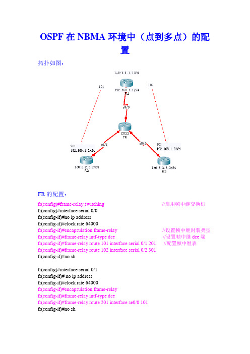
OSPF在NBMA环境中(点到多点)的配置拓扑如图:FR的配置:fr(config)#frame-relay switching //启用帧中继交换机fr(config)#interface serial 0/0fr(config-if)#no ip addressfr(config-if)#clock rate 64000fr(config-if)#encapsulation frame-relay //设置帧中继封装类型fr(config-if)#frame-relay intf-type dce //设置帧中继dce端fr(config-if)#frame-relay route 101 interface serial 0/1 201 //配置帧中继表fr(config-if)#frame-relay route 102 interface serial 0/2 301fr(config-if)#no shfr(config)#interface serial 0/1fr(config-if)# no ip addressfr(config-if)#clock rate 64000fr(config-if)#encapsulation frame-relayfr(config-if)#frame-relay intf-type dcefr(config-if)#frame-relay route 201 interface se0/0 101fr(config-if)#no shfr(config)#interface serial 0/2fr(config-if)#no ip addfr(config-if)#clock rate 64000fr(config-if)#encapsulation frame-relayfr(config-if)#frame-relay intf-type dcefr(config-if)#frame-relay route 301 interface serial 0/0 102fr(config-if)#no shR1配置:Router(config)#hostname r1r1(config)#no ip domain-lookupr1(config)#interface loopback 0r1(config)#ip address 1.1.1.0 255.255.255.0r1(config)#interface serial 0/0r1(config)#no ip addressr1(config-if)#encapsulation frame-relay //设置帧中继封装类型r1(config-if)#no frame-relay inverse-arp //关闭自动映射r1(config-if)#no shr1(config)#interface serial 0/0.1 multipoint //启用点到多点子接口r1(config-subif)#ip add 192.168.1.1 255.255.255.0r1(config-subif)#no shr1(config-subif)#frame-relay map ip 192.168.1.2 101 broadcast //手动映射r1(config-subif)#frame-relay map ip 192.168.1.3 102 broadcastr1(config-subif)#ip ospf network point-to-multipoint //指定网络类型为点到多点r1(config)#router ospf 1r1(config)#network 1.1.1.0 255.255.255.0 area 0r1(config)#network 192.168.1.0 255.255.255.0 area 0R2的配置:router(config)#hostname r2r2(config)#no ip domain-lookupr2(config)#interface loopback 0r2(config)#ip address 2.2.2.0 255.255.255.0r2(config)#interface serial 0/1r2(config-if)#encapsulation frame-relayr2(config-if)#no frame-relay inverse-arpr2(config-if)#ip add 192.168.1.2 255.255.255.0r2(config-if)#no shr2(config-if)#frame-relay map ip 192.168.1.1 201 broadcastr2(config-subif)#ip ospf network point-to-multipoint //指定网络类型为点到多点r2(config)#router ospf 1r2(config)#network 2.2.2.0 255.255.255.0 area 0r2(config)#network 192.168.1.0 255.255.255.0 area 0R3的配置:router(config)#hostname r3r3(config)#no ip domain-lookupr3(config)#interface loopback 0r3(config)#ip address 3.3.3.0 255.255.255.0r3(config)#interface serial 0/2r3(config-if)#ip add 192.168.1.3 255.255.255.0r3(config-if)#no shr3(config-if)#encapsulation frame-relayr2(config-if)#no frame-relay inverse-arpr3(config-if)#frame-relay map ip 192.168.1.1 301 broadcastr3(config-subif)#ip ospf network point-to-multipoint //指定网络类型为点到多点r3(config)#router ospf 1r3(config)#network 3.3.3.0 255.255.255.0 area 0r3(config)#network 192.168.1.0 255.255.255.0 area 0查看FR的帧中继表:查看R1的路由表:分别查看R2、R3的路由表查看ospf的网络类型:用R2 ping R3的lo0口:。

OSPF实验步骤及结果⼀、拓扑⼆、需求1. 按照拓扑所⽰配置OSPF多区域,另外R3与R6,R4与R6间配置RIPv2。
R1,R2,R3,R4的环回接⼝0通告⼊Area 0,R5的通告⼊Area 1,R6的直连接⼝通告⼊RIP中;2. R6上的公司内部业务⽹段192.168.10.0/24和192.168.20.0/24通告⼊RIP中,R5上的公司外部业务⽹段172.16.10.0/24和172.16.20.0/24引⼊OSPF中;3. 在R3,R4上配置OSPF与RIP间的双点双向路由引⼊,将业务⽹段192.168.10.0/24和192.168.20.0/24引⼊到OSPF中;4. 通过配置减少Area 2中维护的LSA条⽬数量,包括Type-3 LSA和Type-5 LSA;5. 通过配置使得R5上的业务⽹段通过R1访问192.168.10.0/24⽹段,通过R2访问192.168.20.0/24⽹段,仅在R3上配置;6. R1与R2间的物理链路状态不稳定,尝试通过适当配置以提⾼OSPF⽹络的健壮性;7. 通过配置解决当前OSPF⽹络中存在的次优路径问题;8. 优化R5的OSPF路由表,减少其需要维护的LSA条⽬,并汇总R5上的两条业务⽹段;9. 根据R2与R4间的链路状况,适当调整OSPF相关计时器10. 为了提⾼OSPF⽹络安全性,部署OSPF区域密⽂认证。
三、实验步骤和结果。
1.按照拓扑所⽰配置OSPF多区域,另外R3与R6,R4与R6间配置RIPv2。
R1,R2,R3,R4的环回接⼝0通告⼊Area 0,R5的通告⼊Area 1,R6的直连接⼝通告⼊RIP中;配置步骤为,相关接⼝配置IP地址,启⽤路由协议,通告⽹段,rip为主类通告。
以R3为例IP地址配置[AR3]dis ip int b*down: administratively down^down: standby(l): loopback(s): spoofingThe number of interface that is UP in Physical is 5The number of interface that is DOWN in Physical is 0The number of interface that is UP in Protocol is 5The number of interface that is DOWN in Protocol is 0Interface IP Address/Mask Physical ProtocolGigabitEthernet0/0/0 10.0.34.3/24 up upGigabitEthernet0/0/1 10.0.13.3/24 up upGigabitEthernet1/0/0 10.0.36.3/24 up upLoopBack0 10.0.3.3/32 up up(s)OSPF配置[AR3]dis cu c ospf[V200R003C00]#ospf 1 router-id 10.0.3.3area 0.0.0.0network 10.0.3.3 0.0.0.0network 10.0.13.3 0.0.0.0area 0.0.0.2network 10.0.34.3 0.0.0.0rip配置[AR3]dis cu configuration rip[V200R003C00]#rip 1version 2network 10.0.0.0查看OSPF邻居[AR3]dis ospf pe brOSPF Process 1 with Router ID 10.0.3.3Peer Statistic Information----------------------------------------------------------------------------Area Id Interface Neighbor id State0.0.0.0 GigabitEthernet0/0/1 10.0.1.1 Full0.0.0.2 GigabitEthernet0/0/0 10.0.4.4 Full---------------------------------------------------------------------------两个full的邻居状态,分别是区域0的10.0.1.1(R1)和区域2的10.0.4.4(R4),查看rip的邻居状态如下[AR3]dis rip 1 ne---------------------------------------------------------------------IP Address Interface Type Last-Heard-Time---------------------------------------------------------------------10.0.34.4 GigabitEthernet0/0/0 RIP 0:0:7Number of RIP routes : 310.0.36.6 GigabitEthernet1/0/0 RIP 0:0:18Number of RIP routes : 2两个rip邻居,分别是10.0.34.4(R4)和10.0.36.6(R6)2. R6上的公司内部业务⽹段192.168.10.0/24和192.168.20.0/24通告⼊RIP中,R5上的公司外部业务⽹段172.16.10.0/24和172.16.20.0/24引⼊OSPF中;R6上的直连⽹段宣告,R5上的业务⽹段引⼊,在引⼊时,只引⼊这两个⽹段,不能引⼊其它⽹段,因此需要做引⼊的限制。

宁波工程学院电子与信息工程学院计算机网络实验实验报告实验名称:实验13 OSPF配置班级:计科12 姓名:学号:实验地点:逸夫楼511 日期:2014.12.15一、实验目的:(1)理解链路状态路由协议与距离矢量路由协议的异同(2)掌握OSPF的基本特点(3)掌握单域OSPF协议的规划与配置(4)掌握路由测试和故障排除方法二、基本技能实验内容、要求和环境:地址表设备接口IP 地址子网掩码默认网关R1 Fa0/0 172.16.1.17 255.255.255.240 不适用S0/0/0 192.168.10.1 255.255.255.252 不适用S0/0/1 192.168.10.5 255.255.255.252 不适用R2 Fa0/0 10.10.10.1 255.255.255.0 不适用S0/0/0 192.168.10.2 255.255.255.252 不适用S0/0/1 192.168.10.9 255.255.255.252 不适用R3 Fa0/0 172.16.1.33 255.255.255.248 不适用S0/0/0 192.168.10.6 255.255.255.252 不适用S0/0/1 192.168.10.10 255.255.255.252 不适用PC1 网卡172.16.1.20 255.255.255.240 172.16.1.17 PC2 网卡10.10.10.10 255.255.255.0 10.10.10.1 PC3 网卡172.16.1.35 255.255.255.248 172.16.1.33(1)任务1:准备网络。
步骤1:根据拓扑图所示完成网络电缆连接。
步骤2:清除路由器上现有的配置。
(2)任务2:配置并激活串行地址和以太网地址。
步骤1:在R1、R2 和R3 上配置接口。
使用拓扑图下方的表中的IP 地址在路由器R1、R2 和R3 上配置接口。

OSPF实验报告袁金星2011年7月目录第一章概述 (2)1.1文档目的 (2)1.2实验目的 (2)第二章实验一总体规划 (3)2.1实验拓扑 (3)2.2实验需求 (3)2.3实验设备及线缆 (3)2.3.1 H3C设备 (3)2.4实验网络设备清单 (3)2.5各设备IP地址分配 (4)2.6各设备主要配置 (4)2.6.1 RTA (4)2.6.2 RTB (5)2.6.3 RTC (6)2.6.4 RTD (7)2.7实验人员和时间 (7)第三章实验一操作方法及步骤 (8)3.1实现区域2里只有1、2、3类LSA (8)3.2区域1里RTC可以引入外部静态路由,没有其他区域外部路由 (8)3.3RTC上只引入172.16.1.0/24和172.16.2.0/24的路由 (9)3.4RTB只发布172.16.1.0/24到骨干区域 (10)3.5RTA上本地路由表中没有172.16.1.0/24的路由 (12)3.6RTD上发布10.1.1.0/24路由。
RTA上禁止此路由发布到AREA0里 (13)第四章实验一实验结果分析 (15)4.1编号1实验结果分析 (15)4.2编号2实验结果分析 (15)4.3编号3实验结果分析 (15)4.4编号4实验结果分析 (15)4.5编号5实验结果分析 (15)4.6编号6实验结果分析 (16)第五章实验一各设备配置相关技术点 (17)5.1配置完全STUB区域 (17)5.2CE1的时隙捆绑.......................................................................................... 错误!未定义书签。
5.3配置管理地址 ............................................................................................. 错误!未定义书签。
实验目的:1、掌握NBMA网络中OSPF的邻居关系手工和自动建立的两种配置方法。
2、掌握指定OSPF的接口优先级和通过修改OSPF的默认接口网络类型避免DR 的选举出错。
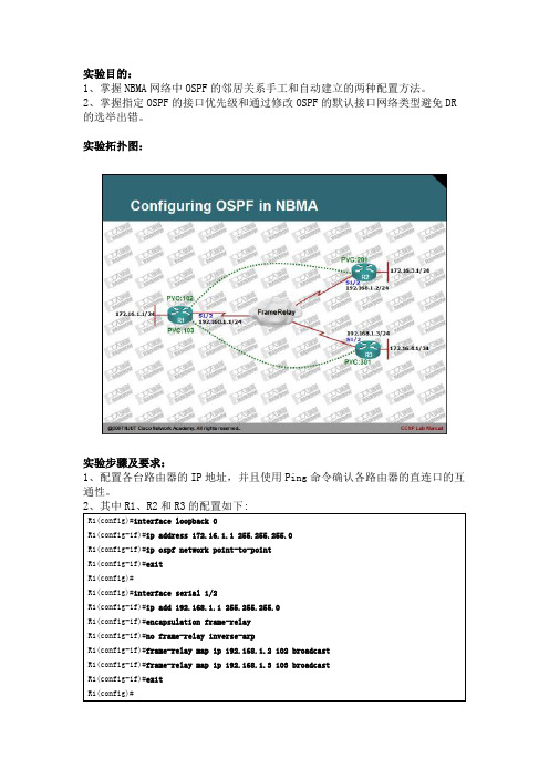
实验拓扑图:实验步骤及要求:1、配置各台路由器的IP地址,并且使用Ping命令确认各路由器的直连口的互通性。
3、在配置完OSPF协议后,查看R1、R2或R3路由器OSPF的邻居表,会发现OSPF主观认为NBMA的广播不支持广播和组播,因此不会主动的向外发送OSPF的HELLO数据包。
够自动的创建OSPF的邻居关系,配置比较简单,也不容易出错。
首先,将之前R1的OSPF邻居表,指出172.16.4.1为DR,172.16.3.1为DROTHER,而自己为BDR。
R2的OSPF邻居表,指出172.16.1.1为BDR,而自己为DR。
R3的OSPF邻居表,指出172.16.1.1为BDR,而自己为DR。
通过如下图示,可以更清楚看出DR和BDR的关系:出现此问题的原因是因为Frame-Relay的网络拓扑非全网状。
R3在与R1在进行邻居创建时,R3并不知道网络中还有R2的存在。
同时,R2与R1进行创建时,也不知晓R3的存在。
此时,在网络中运行的其实是两个不同的OSPF的自治系统。
13、由于上述的问题,还会导致其它原因,比如:R3路由器的172.16.4.0/24的子网出错,R3会向R1通告LSA,R1在收到此LSA后,R1并不会向R3转发,其原因是,R1认为R3是由DR来完成通告的。
其默守OSPF的多路访问网络的更新规则。
另外:如果R1的172.16.1.0/24网络出错,R1默认会向DR通告,即向R3通告,而不会向R2通告,因为R1作为BDR,只需要将LSA通告给DR即可,而其它的DROTHER的通告是由DR完成的,而做为DR的R3在收到R1发送的LSA 后,R3实际上并没有向R2通告,这是因为R3并不知道网络中还有R2的存在。
14、要解决这样的问题,必须手工的指定网络的DR的角色。
5、ospf邻接建立过程描述:首先总结下五报文和七状态1.Down 路由器还末收到邻居发来的HELLO包(1.5) 在NBMA还有个attempt(尝试状态):为NBMA网络中的一个正常过滤状态,即我发送了HELLO等待对方的回应,如果对方不回应则一直滞留在此状态。
2.init 收到来自邻居的hello包,但是hello中未包含自身的信息。
3.two-way 路由器在收到邻居发来的HEELO包中,看到自己的ROUTER-ID ,在这个态开始选举DR和BDR4.exstart 在选举DR和BDR之后,开始选主从Master/Slave5.exchange 主从协商完成后,进行DBD的同步,链路数据库描述(DBD)6.loading DBD同步完成后,进行LSA的同步7.full LSA同步完成之后根据上图做实验分析:在R1和R2启用ospf后,会组播向外发送hello报文。
active neighbor字段中为R1的ROUTER-ID 1.1.1.1 和2.2.2.2,说明进入TWO-WAY状态,并且开始选举DR和BDR选举完成后开始转为extart状态进入exstart state,开始选主从(ROUTER-ID大的为主,作用为了同步DBD的序列号)R1和R2分别向外发DBD报文,都认为自己为主:如图在DBD中I M MS分别表示第一个包、M表示后面还有几个包MS表示为主Interface MTU:在不分片的情况下,此接口最大可发出的IP报文长度为1500。
I(Initial):当发送连续多个DD报文时,如果这是第一个DD报文,则置为1,否则置为0。
M(More):当连续发送多个DD报文时,如果这是最后一个DD报文,则置为0。
否则置为1,表示后面还有其他的DD报文。
MS(Master/Slave):当两台OSPF路由器交换DD报文时,首先需要确定双方的主(Master)从(Slave)关系,Router ID大的一方会成为Master。
OSPF实验一、实验目的1.根据拓扑图完成网络电缆连接2.删除路由器启动配置并将其重新加载到默认状态3.在路由器上执行基本配置任务4.配置并激活接口5.在所有路由器上配置 OSPF 路由6.配置 OSPF 路由器 ID7.使用 show 命令检验 OSPF 路由二、实验环境现有2台2811路由器,2台普通电脑,3根直通线和3根交叉线,组建一个简单的OSPF网络,使路由器和普通电脑之间实现互通。
三、实验拓扑图及地址表四、实验步骤步骤一:准备网络。
1.根据拓扑图所示完成网络电缆连接。
2.清除路由器上现有的配置。
步骤二:在路由器 R1和R2上执行基本配置,代码分别如下:Router>enableRouter#config tRouter(config)#hostname R1R1(config)#enable secret ciscoR1(config)#line console 0R1(config-line)#logging synchronousR1(config-line)#exitR1(config)#line console 0R1(config-line)#password ciscoR1(config-line)#loginR1(config-line)#line vty 0 15R1(config-line)#password ciscoR1(config-line)#loginR1(config-line)#exitR1(config)#service password-encryptionR1(config)#no ip domain-lookupR1(config)#exitR1#copy run startRouter>enableRouter#config tRouter(config)#hostname R2R2(config)#enable secret ciscoR2(config)#line console 0R2(config-line)#logging synchronousR2(config-line)#exitR2(config)#line console 0R2(config-line)#password ciscoR2(config-line)#loginR2(config-line)#line vty 0 15R2(config-line)#password ciscoR2(config-line)#loginR2(config-line)#exitR2(config)#service password-encryptionR2(config)#no ip domain-lookupR2(config)#exitR2#copy run start步骤三:配置并激活串行地址和以太网地址。
OSPF实验及解析:实现OSPF网络实验报告一、实验名称:实现OSPF网络二、实验条件:1、配置路由器运行OSPF协议。
2、拓扑图如(三)所示。
3、要求192.168.1.0/24、192.168.2.0/24为area 1配置为完全末梢区域;192.168.3.0/24为area 0;192.168.4.0/24、192.168.5.0为area 2,配置为NSSA 区域。
路由器D的F0/1端口的辅助IP地址和路由器E运行RIP-V2。
实现OSPF区域的路由器可以和RIP路由器互相学习到网络路径。
三、实验拓扑实现OSPF网络.jpg四、实验步骤及操作:1、路由器A的配置:RouterA(config)#int loopback 0RouterA(config-if)#ip add 172.16.0.1 255.255.255.255 RouterA(config-if)#exitRouterA(config)#int f0/0RouterA(config-if)#ip add 192.168.1.1 255.255.255.0 RouterA(config-if)#no shutRouterA(config-if)#exitRouterA(config)#int f0/1RouterA(config-if)#ip add 192.168.2.1 255.255.255.0 RouterA(config-if)#no shutRouterA(config-if)#exitRouterA(config)#router ospf 10RouterA(config-router)#network 192.168.1.0 0.0.0.255 area 1 RouterA(config-router)#network 192.168.2.0 0.0.0.255 area 1 RouterA(config-router)#area 1 stubRouterA#show ip ospf databaseRouterA#show ip ospf border-router2、路由器B的配置:RouterB(config)#int loopback 0RouterB(config-if)#ip add 172.16.0.2 255.255.255.255 RouterB(config-if)#exitRouterB(config)#int f0/0RouterB(config-if)#ip add 192.168.2.2 255.255.255.0 RouterB(config-if)#no shutRouterB(config-if)#exitRouterB(config)#int f0/1RouterB(config-if)#ip add 192.168.3.1 255.255.255.0 RouterB(config-if)#no shutRouterB(config-if)#exitRouterB(config)#router ospf 10RouterB(config-router)#network 192.168.2.0 0.0.0.255 area 1 RouterB(config-router)#network 192.168.3.0 0.0.0.255 area 0 RouterB(config-router)#area 1 stub no-summary注:设置某区域为完全末梢区域的条件:1、设置内部路由器的区域为末梢区域2、在区域边界路有器上设置该区域为末梢区域且不进行路由汇总3、路由器C的配置:RouterC(config)#int loopback 0RouterC(config-if)#ip add 172.16.0.3 255.255.255.255 RouterC(config-if)#exitRouterC(config)#int f0/0RouterC(config-if)#ip add 192.168.3.2 255.255.255.0RouterC(config-if)#no shutRouterC(config-if)#exitRouterC(config)#int f0/1RouterC(config-if)#ip add 192.168.4.1 255.255.255.0RouterC(config-if)#no shutRouterC(config-if)#exitRouterC(config)#router ospf 10RouterC(config-router)#network 192.168.3.0 0.0.0.255 area 0 RouterC(config-router)#network 192.168.4.0 0.0.0.255 area 2 RouterC(config-router)#area 2 nssa no-summary4、路由器D的配置:RouterD(config)#int loopback 0RouterD(config-if)#ip add 172.16.0.4 255.255.255.255 RouterD(config-if)#exitRouterD(config)#int f0/0RouterD(config-if)#ip add 192.168.4.2 255.255.255.0RouterD(config-if)#no shutRouterD(config-if)#exitRouterD(config)#int f0/1RouterD(config-if)#ip add 192.168.5.1 255.255.255.0RouterD(config-if)#ip add 192.168.6.1 255.255.255.0 secondary RouterD(config-if)#no shutRouterD(config-if)#exitRouterD(config)#router ospf 10RouterD(config-router)#network 192.168.4.0 0.0.0.255 area 2 RouterD(config-router)#network 192.168.5.0 0.0.0.255 area 2 RouterD(config-router)#area 2 nssaRouterD(config-router)#redistribute rip metric 2 metric-type 1 RouterD(config-if)#exitRouterD(config)#router ripRouterD(config-router)#version 2RouterD(config-router)#network 192.168.6.0RouterD(config-router)#redistribute ospf 10 metric 25、路由器E的配置:RouterE(config)#int f0/0RouterE(config-if)#ip add 192.168.6.2 255.255.255.0RouterE(config-if)#no shutRouterE(config-if)#exitRouterE(config)#int f0/1RouterE(config-if)#ip add 192.168.7.1 255.255.255.0RouterE(config-if)#exitRouterE(config)#router ripRouterE(config-router)#version 2RouterE(config-router)#network 192.168.6.0RouterE(config-router)#network 192.168.7.0注:设置某区域为非完全末梢区域的条件:1、设置内部路由器的区域为非完全末梢区域2、在区域边界路有器上设置该区域为非完全末梢区域且不进行路由汇总6、PC工作站的设置:Pc1的设置:IP=192.168.1.10 Netmask=255.255.255.0Pc2的设置:IP=192.168.7.10 Netmask=255.255.255.0五、实验结果及分析在pc1上:Ping+192.168.7.10(通讯正常)在pc2上:Ping+192.168.1.10(通讯正常)由此证明配置成功注一:各Lsa的查看命令1、查看数据库中的所有路由器的Lsa的命令:show ip ospf database router2、查看数据库中的网络Lsa的命令:show ip ospf database network3、查看数据库中的网络汇总Lsa的命令:show ip ospf database summary4、查看数据库中的ASBR汇总Lsa的命令:show ip ospf database asbr-summary5、查看数据库中的自主系统外部Lsa的命令:show ip ospf database external6、查看数据库中的Nssa外部Lsa的命令:show ip ospf database nssa-external【实验环境】BENET公司总部位于北京,在上海和广州拥有分公司,现希望把三个地方的办公网络用OSPF连接起来,希望你为他们实现这个办公网络的搭建!【实验目的】按照现有拓扑图的规划,配置多区域的OSPF在他的上面配置末梢区域(Stub Area)和完全末梢区域(Totally Stublly Area)以及知道为什么要换分多区域的原因?【实验拓扑】【实验步骤】网络拓扑图的具体布线:Router1 S0/0 <----> Router2 S0/0Router2 S1/0 <----> Router3 S0/0Router3 E1/0 <----> Router4 E0/0第一步:配置路由器的回环地址和接口的IP地址;(1) 、配置Router1的回环地址和接口的IP地址;(2)、配置Router2的回环地址和接口的IP地址;(注意:在Router2上配置回环地址是根据情况而定的;Router2是属于Area2是属于骨干区域,但同时它也是一个ABR路由器;所以要配置两个接口的IP地址;因为R2是区域边界系统路由器(ABR)所以在它上面要配置两个接口的IP地址)!(3)、配置Router3的回环地址和接口的IP地址(他和Router2一样是一个ABR路由器又是Area0所以要配置两个接口的IP地址;而回环地址就在这里不在做具体的介绍了;因为R3是区域边界路由器(ABR)所以在它上面要配置两个接口的IP地址)(4)、配置Router4的回环地址和接口的IP地址;(他和Router2一样是一个ABR路由器又是Area0所以要配置两个接口的IP地址;而回环地址就在这里不在做具体的介绍了)第二步:启动OSPF的进程,并配置他们的区域末梢区域(Stub Area)和完全末梢区域(Totally Stubby Area)(1)、在Router1上配置OSPF进程以及宣告他所在的末梢区域(Stub Area)(注意:宣告OSPF的进程和宣告RIP的进程的配置是不一样的,在配置OSPF时他的进程号时本地路由器的进程号,他是来标识一台路由器的多个OSPF的进程的;)末梢区域(Stub Area )他是一个不允许自治系统外部LSA通告在其内进行泛洪的区域。
OSPF综合实验大全OSPF实验1:基本的OSPF配置实验级别:Assistant实验拓扑:实验步骤:1.首先在3台路由器上配置物理接口,并且使用ping命令确保物理链路的畅通。
2.在路由器上配置loopback接口:R1(config)#int loopback 0R1(config-if)#ip add 1.1.1.1 255.255.255.0R2(config)#int loopback 0R2(config-if)#ip add 2.2.2.2 255.255.255.0R3(config)#int loopback 0R3(config-if)#ip add 3.3.3.3 255.255.255.0路由器的RID是路由器接口的最高的IP地址,当有环回口存在是,路由器将使用环回口的最高IP地址作为起RID,从而保证RID的稳定。
3.在3台路由器上分别启动ospf进程,并且宣告直连接口的网络。
R1(config)#router ospf 10R1(config-router)#network 192.168.1.0 0.0.0.255area 0R1(config-router)#network 1.1.1.0 0.0.0.255 area 0R1(config-router)#network 192.168.3.0.0.0.255 area 0ospf的进程号只有本地意义,既在不同路由器上的进程号可以不相同。
但是为了日后维护的方便,一般启用相同的进程号。
ospf使用反向掩码。
Area 0表示骨干区域,在设计ospf网络时,所有的非骨干区域都需要和骨干区域直连!R2,R3的配置和R1类似,这里省略。
不同的是我们在R2和R3上不宣告各自的环回口。
*Aug 13 17:58:51.411: %OSPF-5-ADJCHG: Process 10, Nbr 2.2.2.2 on Serial1/0 from LOADING to FULL, Loading Done配置结束后,我们可以看到邻居关系已经到达FULL状态。
实验拓扑图:
实验环境说明:
1.将路由器R5的Fa0/0端口的ip设为:19
2.168.4.5/24;S1/1端口的ip设为:192.168.
3.5/24
2.将路由器R1的S1/1端口的ip设为:192.168.
3.1/24;S1/2端口的ip设为:192.168.
2.1/24
3.将路由器R2的S1/2端口的ip设为:192.168.2.2/24;Fa0/0端口的ip设为:192.168.
1.2/24
前言:我们都知道,OSPF的网络类型有:广播型(也称多路访问)、点到点、点到多点、非广播多路访问(NBMA),除了非广播型多点访问类型以外的其它类型都会自动选择DR和BDR,这样才会形成邻居,网络之间才可以互相通信。
而我们今天要演示的OSPF在NBMA中的实现,就是要克服这种非广播型多路访问中无法自动选出DR和BDR而无法发现邻居。
没有邻居的路由器之间是无法通信的。
我们的解决思路主要有:1、手工为相应的端口指定邻居;2、改变相应端口的网络类型。
下面请看我们的详细配置过程:
配置过程清单:
交换机SW1的配置:
分别将Fa1/11、Fa1/14端口设置为全双工模式:
SW1(config)#int fa1/11
SW1(config-if)#speed 100
SW1(config-if)#duplex full
SW1(config-if)#no shut
SW1(config-if)#exit
SW1(config)#int fa1/14
SW1(config-if)#speed 100
SW1(config-if)#duplex full
SW1(config-if)#no shut
SW1(config-if)#exit
路由器R2的配置清单:
1、分别为路由器R2的S1/
2、Fa0/0端口设置iP:
R2(config)#int s1/2
R2(config-if)#ip add 192.168.2.2 255.255.255.0
R2(config-if)#no shut
R2(config)#int fa0/0
R2(config-if)#speed 100
R2(config-if)#duplex full
R2(config-if)#ip add 192.168.1.2 255.255.255.0
R2(config-if)#no shut
R2(config-if)#exit
2、在路由器R2上配置OSPF:
R2(config)#router ospf 100
R2(config-router)#router-id 2.2.2.2
R2(config-router)#network
R2(config-router)#network 192.168.2.2 0.0.0.0 a 0
R2(config-router)#network 192.168.1.2 0.0.0.0 a 0
R2(config-router)#exit
路由器R1的配置清单:
1、为路由器R1的S1/1端口设置ip并封装桢中继:(//后面为注释说明)
R1(config)#int s1/1
R1(config-if)#ip add 192.168.3.1 255.255.255.0
R1(config-if)#encapsulation frame-relay
R1(config-if)#frame-relay map ip 192.168.3.5 105 br //使用br关键字模拟广播R1(config-if)#no frame-relay inverse-arp
R1(config-if)#no shut
2、为路由器R1的S1/2端口设置ip:
R1(config)#int s1/2
R1(config-if)#ip add 192.168.2.1 255.255.255.0
R1(config-if)#no shut
3、在路由器R1上配置OSPF:
R1(config)#router ospf 100
R1(config-router)#router-id 1.1.1.1
R1(config-router)#network 192.168.3.1 0.0.0.0 a 0
R1(config-router)#network 192.168.2.1 0.0.0.0 a 0
R1(config-router)#exit
路由器R5的配置清单:
1、为路由器R5的S1/1端口配置ip并封装桢中继:
R5(config)#int s1/1
R5(config-if)#ip add 192.168.3.5 255.255.255.0
R5(config-if)#encapsulation frame-relay
R5(config-if)#frame-relay map ip 192.168.3.1 501 br //使用br关键字模拟广播
R5(config-if)#no frame-relay inverse-arp
R5(config-if)#no shut
R5(config-if)#exit
2、为路由器R5的Fa0/0端口配置ip并设为全双工模式:
R5(config)#int fa0/0
R5(config-if)#speed 100
R5(config-if)#duplex full
R5(config-if)#ip add 192.168.4.5 255.255.255.0
R5(config-if)#no shut
R5(config-if)#exit
3、在路由器R5上配置OSPF:
R5(config)#router ospf 100
R5(config-router)#router-id 5.5.5.5
R5(config-router)#network 192.168.4.5 0.0.0.0 a 0
R5(config-router)#network 192.168.3.5 0.0.0.0 a 0
R5(config-router)#exit
以上为正常的配置过程,如果我们来通过#show ip ospf nei命令来看看R1、R5的邻居表,你会发现它们的邻居表中根本没有对方,也就是说,它们之间根本没有发现邻居,这时整个网络的通信就会到这里出现故障而无法通信。
在前面我们已经说过,非广播型多路访问是不会自动选出DR和BDR的,需要我们手工来指定。
这时我们就有了两种思路:1、改变R1 、R5之间的网络类型,将它们改变为点对多点(point-to-mu,这里演示的是点对点的拓扑,现实中就是点对多点的拓扑了);2、手工为它们指定邻居。
请看下面的配置,这就是关键所在:
A:改变网络类型实现OSPF在桢中继可以发现邻居:
1、改变R1的S1/1的网络类型为“点对多点”:
R1(config)#int s1/1
R1(config-if)#ip ospf network point-to-mu //改变网络类型为点对多点
R1(config-if)#no shut
2、改变R5的S1/1的网络类型为“点对多点”:
R5(config)#int s1/1
R5(config-if)#ip ospf network point-to-mu //改变网络类型为点对多点
R5(config-if)#no shut
这时,我们使用#show ip ospf nei命令来查看R1的邻居表:
R1#show ip ospf nei
Neighbor ID Pri State Dead Time Address Interface
5.5.5.5 0 FULL/ - 00:01:47 192.168.3.5 Serial1/1
2.2.2.2 0 FULL/ - 00:00:33 192.168.2.2 Serial1/2
看到了吧,路由器R1的邻居表里面已经有了R5和R2,这时,我们再用ping命令来验证一下,我们用R1来pingR5:
R1#ping 192.168.4.5
Type escape sequence to abort.
Sending 5, 100-byte ICMP Echos to 192.168.4.5, timeout is 2 seconds:
!!!!!
Success rate is 100 percent (5/5), round-trip min/avg/max = 44/73/112 ms 成功了!同样的道理,R5我们就不再验证了,您看明白了吗?
B:手工为R1、R5指定邻居:(//后面为注释)
R1(config)#router ospf 100
R1(config)#nei 192.168.3.5 //指定R5是R1的邻居,这里写对方的ip
R5(config)#router ospf 100
R5(config)#nei 192.168.3.1 //指定R1是R5的邻居,这里写对方的ip
验证的过程在此省略,不明白的地方欢迎留言提问。