
Roping in 6111 aluminum alloys with various iron contents
- 格式:pdf
- 大小:681.16 KB
- 文档页数:8

Lesson 2 Carbon and Alloy SteelTEXTSteel is probably the most widely used material for machine elements because of its properties of high strength, high stiffness, durability and relative ease of fabrication. The term steel refers to and alloy of iron, carbon, manganese and one or more other significant elements. Carbon has a very strong effect on the strength, hardness and ductility of any steel alloy. The other elements affect hardenability, toughness, corrosion resistance, machinability and strength retention at high temperatures. The primary alloying elements present in the various alloy steels are sulfur, phosphorus, silicon, nickel, chromium, molybdenum and vanadium.1.Importance of CarbonAlthough most steel alloys contain less than 1.0% carbon, it is included in the designation because of its effect on the properties of steel. As Figure 1.2illustrates, the last tow digits indicate carbon content n hundredths of a percent.As carbon content increases, strength and hardness also increase under the same conditions of processing and heat treatment. Since ductility decreases withincreasing carbon content, selecting suitable steel involves some compromisebetween strength and ductility.As a rough classification scheme, a low-carbon steel is one having fewer than30 points of carbon (0.30%). These steels have relatively low strength but goodformability. In machine element applications where high strength is not required, low-carbon steels are frequently specified. If wear is a potential problem,low-carbon steels can be carburized to increase the carbon content in the veryouter surface of the part and to improve the combination of properties.Medium-carbon steels contain 30 to 50 points of carbon (0.30%-0.50%).Most machine elements having moderate to high strength requirements withfairly good ductility and moderate hardness requirements come from this group.High-carbon steels have 50 to 95 points of carbon (0.50%-0.95%). The high carbon content provides better wear properties suitable for applications requiringdurable cutting edges and for applications where surfaces are subjected to constant abrasion. Tools, knives, chisels, and many agricultural implement components are among these uses.2.Stainless SteelsThe term stainless steel characterizes the high level of corrosion resistance. To be classified as a stainless steel, the alloy must have a chromium content of at least 10%. Most have 12% to 18% chromium.The three main groups of stainless steels are austenitic, ferritic, and martensitic. Austenitic stainless steels fall into the AISI 200 and 300 series. They are general-purpose grades with moderate strength. Most are not heat-treatable, and their final properties are determined by the amount of working. These alloys are nonmagnetic and are typically used in food processing equipment.Ferritic stainless steels belong to the AISI 400 series, designated as 405, 409, 430, 446, and so on. They are magnetic and perform well at elevated temperatures, from 1300℉to 1900℉(700℃-1040℃). They are notheat-treatable, but they can be cold-worked to improve properties. Typical applications include heat exchanger tubing, petroleum refining equipment, automotive trim, furnace parts, and chemical equipment.Martensitic stainless steels are also members of the AISI 400 series, including 403, 410, 414, 416, 420, 431 and 440 types. They are magnetic, can be heat-treated, and have higher strength than the AISI 200 and 300 series, while retaining good toughness. Typical uses include turbine engine parts, cutlery, scissors, pump parts, valve parts, surgical instruments, aircraft fittings, and marine hardware.3.Structural SteelsMost structural steels are designated by ASTM numbers established by American Society for Testing and Materials. The most common grade is ASTMA36, which has a minimum yield point of 36000 psi (248MPa) and is very ductile. It is basically a low-carbon, hot-rolled steel available in sheet, plate, bar, and structural shapes, such as wide-flange beams, American standard beams, channelsand angles.Most wide-flange beams are currently made using ASTM A992 structural steel, which has a yield point of 50 ksi to 65 ksi and a minimum tensile strength of 65 ksi. An additional requirement is that the maximum ratio of the yield point to the tensile strength is 0.85. This is a highly ductile steel, having a minimum of 21% elongation in a 2.00-inch gage length. Using this steel instead of the lower strength ASTM A36 steel typically allows smaller, lighter structural members at little or no additional cost.Hollow structural sections (HSS) are typically made from ASTM A500 steel that is cold-formed and either welded or made seamless. Included are round tubes and square rectangular shapes. There are different strength grades can bespecified. Some of these HSS products are made from ASTM A501 hot-formed steel having properties similar to the ASTM A36 hot-rolled steel.Many higher-strength grades of structural steel are available for use in construction, vehicular, and machine applications. They provide yield points in the range from 42 000 psi to 10 000 psi (290 MPa-700MPa).4.Tool SteelsTool steels refers to a group of steels typically used for cutting tools, punches, dies, shearing blades, chisels and similar uses. The numerous varieties of toolsteel materials have been classified into seven general types. Whereas most uses of tool steels are related to the field of manufacturing engineering, they are also pertinent to machine design where the ability to maintain a keen edge underabrasive conditions is required. Also, some tool steels have rather high shockresistance which may be desirable in machine components such as parts formechanical clutches, pawls, blades, guides for moving materials and clamps.READING MATERIALThe final properties of steels are dramatically affected by the way the steels are produced. Some processes involve mechanical working, such as rolling toa particular shape or drawing through the dies. In machine design, many bar-shaped parts, shafts, wire and structural members are produced in these ways. But most machine parts, particularly those carrying heavy loads, are heat-treated to produce high strength with acceptable toughness and ductility.Carbon steel bar and sheet forms are usually delivered in the as-rolling condition, that is, they are rolled at an elevated temperature that eases the rolling process. The rolling can also be done cold to improve strength and surface finish. Cold-drawn bar and wire have the highest strength of the forms, along with a very good surface finish. However, when a material is designated to be as-rolled, it should be assumed that it was hot-rolled.1.Heat TreatingHeat treating is the process in which steel is modified its properties by different elevated temperatures. Of the several processes available, those most used for machine steels are annealing, normalizing, through-hardening (quench and temper), and case hardening.Figure 1.3 shows the temperature-time cycles for these heat treating processes. The symbol RT indicates normal room temperature, and LC refers to the lower critical temperature at which the ferrite transformation begins during the heating of the steel. At the upper critical temperature (UC), the transformation is complete. These temperatures vary with the composition of the steel. For most medium-carbon (0.30%—0.50%) steels. UC is approximately 1 500°F(822℃). References giving detailed heat treating process data should be consulted.1)AnnealingFull annealing (Figure 1.3(a)) is performed by heating the steel above the upper critical temperature and holding it until the composition is uniform. Then the steel is cooled very slowly in the furnace until its temperature is below the lower critical temperature. Slow cooling to room temperature outside the furnace completes the process. This treatment produces a soft, low-strength form of the material, free of significant internal stresses. Parts are frequentlycold-formed or machined in the annealed condition.Stress relief annealing (Figure 1.3 (b)) is often used following welding, machining, or cold forming to relieve residual stresses and thereby minimize subsequent distortion. The steel is heated to approximately 1 000 °F to 1 200 °℉(540℃—650℃), held to achieve uniformity, and then slowly cooled in still air to room temperature.NormalizingNormalizing (Figure 1.3 (c)) is similar to annealing, but at a higher temperature, above the transformation range where austenite is formed, approximately 1 600 ℉(870℃). The result is a uniform internal structure in the steel and somewhat higher strength than annealing produces. Machinability and toughness are usually improved over the as-rolled condition.2.Through-Hardening and Quenching and TemperingThrough-hardening (Figure 1.3(d)) is accomplished by heating the steel to above the transformation range where austenite forms and then rapidly cooling it in a quenching medium. The rapid cooling causes the formation of martensite, the hard and strong form of steel. The properties of the martensite forms depend on the alloy’s composition. An alloy containing a minim um of 80% of its structure in the martensite form over the entire cross section has high hardenability. This is an important property to look for when selecting a requiring high strength and hardness steel. The common quenching media are water, brine, and special mineral oils. The selection of a quenching medium depends on the required cooling rate. Most machine steels use either oil or water quenching.Tempering is usually performed immediately after quenching and involves reheating the steel from a temperature of 400℉to 1 300℉(200℃—700℃) and then slowly cooling it in air to room temperature. This process modifies the steel’s properties. Tensile strength and yield strength decrease with increasing tempering temperature, whereas ductility improves, as indicated by an increase in the percent elongation. Thus, the designer can tailor the propertiesof the steel to meet specific requirements. Furthermore, the steel in its as-quenched condition has high internal stresses and is usually quite brittle. Machine parts should normally be tempered at 700 ℉(370℃) or higher after quenching.(a)full annealing (b) stress relief annealing(c) normalizing (d) quenching and tempering(through-hardening)Figure 1. 3 Heat treatments for steels3. Case HardeningIn many cases, many parts require only moderate strength although the durface must have a very high hardness. In gear teeth, for example, high surface hardness is necessary to resist wearing as the mating teeth come into contact several million times during the expected life of the gears. At each contact, a high stress happens at the surface of the teeth. In this condition, case hardening is used. The surface (or case) of the part is given a high hardness to a depth of perhaps 0.010 in to 0.040 in (0.25 mm—1.00 mm), although the interior of the part (the core) is affected only slightly, if at all. Theadvantage of surface hardening is that as the surface receives the required wear-resisting hardness, the core of the part remains in a more ductile form which is resistant to impact and fatigue. The most used processes of case hardening are flame hardening, induction hardening, carburizing, nitriding, cyaniding, carbo-nitriding.。
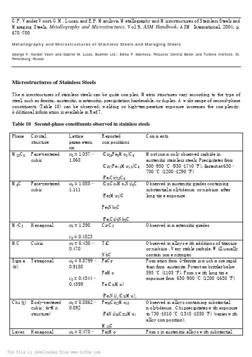
G.F. Vander Voort, G.M. Lucas, and E.P. Manilova, Metallography and Microstructures of Stainless Steels and Maraging Steels, Metallography and Microstructures,Vol 9, ASM Handbook, ASM International, 2004, p. 670–700Metallography and Microstructures of Stainless Steels and Maraging SteelsGeorge F. Vander Voort and Gabriel M. Lucas, Buehler Ltd.; Elena P. Manilova, Polzunov Central Boiler and Turbine Institute, St. Petersburg, RussiaMicrostructures of Stainless SteelsThe microstructures of stainless steels can be quite complex. Matrix structures vary according to the type of steel, such as ferritic, austenitic, martensitic, precipitation hardenable, or duplex. A wide range of second-phase constituents (Table 10) can be observed; welding or high-temperature exposure increases the complexity. Additional information is available in Ref 7.Table 10 Second-phase constituents observed in stainless steelsPhase Crystalstructure Latticeparameters,nmReportedcompositionsCommentsM23C6Face-centeredcubic a0 = 1.057–1.068(Cr16Fe5Mo2)C6(Cr17Fe4.5Mo1.5)C6(Fe,Cr)23C6Most commonly observed carbide inaustenitic stainless steels. Precipitates from500–950 °C (930–1740 °F), fastest at 650–700 °C (1200–1290 °F)M6C Face-centeredcubic a0 = 1.085–1.111(Cr,Co,Mo,Ni)6C(Fe3Mo3)CFe3Nb3C(Fe,Cr)3Nb3CObserved in austenitic grades containingsubstantial molybdenum or niobium afterlong time exposureM7C3Hexagonal a0 = 1.398c0 = 0.4523Cr7C3Observed in martensitic gradesMC Cubic a0 = 0.430–0.470TiCNbC Observed in alloys with additions of titanium or niobium. Very stable carbide. Will usually contain some nitrogenSigma (σ) Tetragonal a0 = 0.8799–0.9188c0 = 0.4544–0.4599FeCrFeMoFe(Cr,Mo)(Fe,Ni)x(Cr,Mo)yFormation from δ-ferrite is much more rapidthan from austenite. Potent embrittler below595 °C (1105 °F). Forms with long timeexposure from 650–900 °C (1200–1650 °F)Chi (χ) Body-centeredcubic: (α-Mnstructure) a0 = 0.8862–0.892Fe36Cr12Mo10(FeNi)36Cr18Mo4M18CObserved in alloys containing substantialmolybdenum. Chi precipitates with exposureto 730–1010 °C (1345–1850 °F) (varies withalloy composition).Laves Hexagonal a0 = 0.470–Fe2Mo Forms in austenitic alloys with substantial The file is downloaded from (η)0.4744c 0 = 0.772–0.7725(Ti 21Mo 9)(Fe 50Cr 5Si 5) amounts of molybdenum, titanium, or niobium after long time exposure from 600–1100 °C (1110–2010 °F) Austenitic Stainless Steels. The most commonly used stainless steels are the austenitic grades, of which AISI 302, 304, and 316 are the most popular wrought grades, and CF-8 and CF-8M are the most popular cast grades. These grades contain 16% or more chromium, a ferrite-stabilizing element, and sufficient austenite-stabilizing elements, such as carbon, nitrogen, nickel, and manganese, to render austenite stable at room temperature. The grades containing silicon, molybdenum, titanium, or niobium—AISI 302B, 316, 317, 321, and 347, for example—will sometimes include a minor amount of δ-ferrite because of the ferrite-stabilizing influence of these elements.Alloys with substantial nickel are fully austenitic, for example, AISI 310 or 330. For alloys susceptible to δ-ferrite stabilization, the amount present will depend on the composition, chemical homogeneity, and hot working. Alloys with especially low carbon contents to minimize susceptibility to sensitization during welding (AISI 304L, 316L, or 317L, for example) will have a greater tendency toward δ-ferrite stabilization. Figure 26 shows examples of δ-ferrite stringers in wrought 203, 302-HQ, 304, and 316L stainless steels.Fig. 26 Examples of δ-ferrite stringers (arrows) in austenitic stainless steels. (a) 203 etched with Ralph's reagent. (b) 302-HQ etched with waterless Kalling's reagent. (c) 316L etched with glyceregia. (d) 304 etched with aqueous 20% NaOH at 3 V dc for 20 sAlloys CF-3 through CF-16F in Table 3 are austenitic, with limited amounts of ferrite; alloys CF-20, CK-20, and CN-7M are completely austenitic. They exhibit maximum corrosion resistance in the solution-treated condition. The corrosion resistance of certain alloys is enhanced by extralow carbon content (as in CF-3), a molybdenum addition (as in CF-3M and CF-8M), or the addition of niobium (as in CF-8C). Alloy CF-16F contains 0.20 to 0.35% Se for improved machinability. Figure 27 shows the microstructure of as-cast and as-cast and solution-annealed CF-8M. Figure 28 shows the microstructure of as-cast type 301, and Fig. 29 shows the microstructure of as-cast 316 stainless steel (wrought grades before hot working). Note that in the as-cast condition, both contain substantial ferrite. However, after hot working, they will be free or nearly free of ferrite.Fig. 27 Ferrite in CF-8M stainless steel in the (a) as-cast condition and (b) after solution annealing. Revealed using glyceregiaThe file is downloaded from Fig. 28 As-cast microstructure of type 301 stainless steel, revealed using Ralph's reagent. (a) Bright field.(b) Nomarski differential interference contrastFig. 29 As-cast microstructure of 316 stainless steel contains considerable δ-ferrite. Revealed using glyceregia.Numerous studies have been conducted to predict matrix phases based on chemical composition. Most of these studies have concentrated on predicting weldment microstructures (Ref 8, 9, 10, 11, 12, 13, 14, 15); others have concentrated on predicting cast microstructures (Ref 16, 17, 18) or predicting structures at the hot-working temperature (Ref 19) or after hot working (Ref 20). Measurement of the δ-ferrite content of stainless steels, particularly weldments, has been widely studied (Ref 21, 22, 23, 24).The austenite in these grades is not stable but metastable. Martensite can be formed, particularly in the leaner grades, by cooling specimens to very low temperatures or by extensive plastic deformation. Nonmagnetic, hexagonal close-packed ε-martensite and magnetic, body-centered cubic (bcc) α′-martensite have been observed. Empirical relationships have been developed to show how composition influences the resistance of such steel to deformation-induced martensite (Ref 25, 26). Figure 30 shows examples of martensite formed in cold-worked specimens of 203, 303, 303Se, and 304 stainless steels. In alloys where the austenite is more stable, cold working does not produce martensite. Because austenitic alloys are face-centered cubic, they have twelve well-developed slip systems, and only slip lines are observed, as shown in the examples for 302-HQ and 316L in Fig. 31. Figure 32 shows the slip in type 347 stainless steel, cold drawn with 5, 10, 15, and 30% The file is downloaded from reductions. Cold drawing affects the metal at the surface far more than in the interior; thus, the slip line density will be highest at the surface and lowest at the center.Fig. 30 Martensite (arrows) produced by cold working austenitic stainless steels. (a) 203 etched with Ralph's reagent. (b) 303 etched with Ralph's reagent. (c) 303 etched with Lucas reagent. (d) 303Se etched with waterless Kalling's reagent. (e) 304 etched with Vilella's reagent. (f) Same specimen as in (e) but higher magnificationFig. 31 Slip produced by cold working. (a) 302-HQ etched with waterless Kalling's reagent. (b) 316L stainless steel etched with glyceregiaFig. 32 Slip near the surface of cold-drawn 347 stainless steel reduced (a) 5%, (b) 10%, (c) 15%, and (d) 30% in diameter. Revealed using aqueous 60% HNO3 at 4 V dcCarbon content limits are generally 0.03, 0.08, or 0.15% in the austenitic grades. Solution annealing will usually dissolve all, or most of, the carbides present after hot rolling. Rapid quenching from the solution-annealing temperature of generally 1010 to 1065 °C (1850 to 1950 °F) will retain the carbon in solution, producing a strain-free, carbide-free austenitic microstructure. Some of these grades are water quenched from the hot working temperature. When properly performed, the solution-annealed structure should exhibit a single grain size distribution, with equiaxed grains containing annealing twins. Examples for a number of alloys are given in Fig. 33. The more highly alloyed grades can be quite difficult to etch and obtain full delineation of the grain structure. In such cases, use of Nomarski differential interference contrast illumination is very helpful in bringing out the grain structure as well as the alloy segregation, as shown in Fig. 33(i) to (l). However, grain structures are not always equiaxed and unimodal, especially in as-hot-worked specimens. Figure 34 shows examples of bimodal grain size distributions in austenitic stainless steels.The file is downloaded from Fig. 33 Austenitic grain boundaries revealed in (a) 302-HQ etched with waterless Kalling's, (b) 304 Modified etched with aqueous 60% HNO3 at 1 V dc for 90 s, (c) 316L etched as in (b) but for 20 s, (d) concast 316 etched with aqueous 60% HNO3 at 1.5 V dc for 60 s, (e) 330 etched as in (d), (f) Nitronic 50 etched with glyceregia, (g) 18-18 PLUS etched with 15 HCl-10 HNO3-10 acetic acid, (h) 20 Mo-6 etched as for (g), (i) AL-6XN plate etched as in (g), (j) same field as (i) but viewed with Nomarski differential interference contrast, (k) SCF-23 etched as in (g), and (l) same field as (k) but viewed with Nomarski differential interference contrast. (g) and (h) also viewed with Nomarski DIC.Fig. 34 Duplex grain structures observed in (a) Nitronic 50 etched with glyceregia, (b) SCF-19 etched with aqueous 60% HNO3 at 1 V dc for 60 s (“necklace”-type condition), (c) 22-13-5 etched with waterless Kalling's reagent, and (d) 330 etched as in (b) but at 1.5 V dcThe most widely observed carbide type in austenitic stainless steels is M23C6, which is often referred to as Cr23C6, but more properly is (Cr, Fe)23C6or (Cr, Fe, Mo)23C6. The precipitation of this carbide at grain boundaries during welding produces intergranular corrosion. To counter sensitization during welding, carbon contents are reduced or strong carbide formers are added, as in AISI 321 and 347.Precipitation of M23C6 carbide occurs as a result of heating solution-annealed grades to 500 to 950 °C (930 to 1740 °F); the fastest rate of precipitation takes place from 650 to 700 °C (1200 to 1290 °F). Precipitation occurs first at austenite/δ-ferrite phase boundaries, when present, followed by precipitation at other noncoherent interfaces (grain and twin boundaries), and finally by precipitation at coherent twin boundaries. In addition, M23C6 may precipitate at inclusion/matrix-phase boundaries.The appearance of M23C6varies with the precipitation temperature and time. It is most easily studied using extraction replicas. At the lower precipitation temperatures, M23C6has a thin, continuous, sheetlike morphology. When the precipitation temperature is 600 to 700 °C (1110 to 1290 °F), feathery dendritic particles form at boundary intersections. With time, these precipitates coarsen and thicken. At still higher precipitation temperatures, M23C6forms at grain boundaries as discrete globular particles whose shape is influenced by the boundary orientation, degree of misfit, and temperature (Ref 27). The M23C6 that precipitates at noncoherent twin boundaries is lamellar or rodlike; that which precipitates at coherent twin boundaries is platelike. The M23C6that forms at the lower precipitation temperatures is most detrimental to intergranular corrosion resistance. Examples of sensitized grain structures are shown in Fig. 35.The file is downloaded from Fig. 35 Grain-boundary carbides in sensitized (a) 304 etched with Ralph's reagent, (b) 304 etched with aqueous 10% ammonium persulfate at 6 V dc for 10 s, and (c) 316 etched as in (a)Alloys given deliberate minor additions of titanium or niobium—AISI 321 and 347, for example—form titanium or niobium carbides, rather than M23C6. To take full advantage of these additions, solution-annealed specimens are subjected to a stabilizing heat treatment to precipitate the excess carbon as titanium or niobium carbides. This treatment is commonly used with AISI 321 and involves holding the specimen several hours at 845 to 900 °C (1550 to 1650 °F). These MC-type carbides will precipitate intragranularly at dislocations or stacking faults within the matrix. Some may also precipitate on grain boundaries.Additions of titanium or niobium must be carefully controlled to neutralize the carbon in solution. In practice, titanium and niobium carbides can contain some nitrogen, and both can form rather pure nitrides. Titanium nitrides usually appear as distinct, bright-yellow cubic particles. Titanium carbide is grayish, with a less regular shape. Titanium carbonitride will have an intermediate appearance that varies with the carbon/nitrogen ratio. Chromium nitrides are not usually observed in the austenitic grades, unless the service environment causes substantial nitrogen surface enrichment or they are nitrogen strengthened.Carbides of the M6C type are observed in austenitic grades containing substantial molybdenum or niobium additions. It usually precipitates intragranularly. For example, in AISI 316 with 2 to 3% Mo, M6C will form after approximately 1500 h at 650 °C (1200 °F). Several types of M6C have been observed, including Fe3Mo3C, Fe3Nb3C, and (Fe, Cr)3Nb3C.Several types of sulfides have been observed in austenitic grades. The most common form is MnS. However, if the manganese content is low, chromium will replace some of the manganese in the sulfide. At manganese contents less than approximately 0.20%, pure chromium sulfides will form. Because these are quite hard, machinability (tool life) will be poor. Figure 36 shows manganese sulfides in types 203 and 303 resulfurized austenitic grades. Some free-machining grades have additions of selenium and sulfur to form manganese selenides as well as manganese sulfides. Figure 30(d) shows the manganese selenides in 303Se. In grades with substantial titanium, several forms of titanium sulfides have been observed, including Ti2S, Ti2SC, and Ti4C2S2. The file is downloaded from Fig. 36 Examples of the grain structures of resulfurized stainless steels revealed using Ralph's reagent.(a) and (b) 203. (c) and (d) 303Several intermetallic phases may be formed by high-temperature exposure. These phases form from titanium, vanadium, and chromium (“A” elements) and from manganese, iron, cobalt, and nickel (“B” elements). Some of these phases are stoichiometric compounds. Probably the most important is σ phase, first observed in 1927. The leaner austenitic grades free of δ-ferrite are relatively immune to σ-phase formation, but the higher alloy grades and those containing δ-ferrite are prone to its formation. Sigma is frequently described as FeCr, although its composition can be quite complex and variable, ranging from B4A to BA4.Certain elements, such as silicon, promote σ-phase formation. Cold working also enhances subsequent σ-phase formation. Empirical equations based on composition have been developed to predict the tendency toward σ-phase formation (Ref 28, 29). Sigma is a very potent embrittler whose effects are observable at temperatures below approximately 595 °C (1100 °F). Sigma also reduces resistance to strong oxidizers. The morphology of σphase varies substantially. Etching techniques (Ref 5, 30, 31, 32) have been widely used to identify σ phase in stainless steels (Fig. 19), but x-ray diffraction is more definitive. Although its crystal structure is tetragonal, σphase does not respond to crossed-polarized light.Chi phase (Ref 33, 34, 35, 36, 37, 38) is observed in alloys containing substantial additions of molybdenum subjected to high-temperature exposure. Chi can dissolve carbon and exist as an intermetallic compound or as a carbide (M18C). It is often observed in alloys susceptible to σ-phase formation and has a bcc, α-manganese-type crystal structure. Several forms of the intermetallic phase have been identified, as shown in Table 10. Chinucleates first at grain boundaries, then at incoherent twin boundaries, and finally intragranularly (Ref 38). Chi varies in shape from rodlike to globular. As with σ phase, cold work accelerates nucleation of χ phase.Laves phase (ηphase) can also form in austenitic stainless steels after long-term high-temperature exposure (Ref 37, 38). Alloys containing molybdenum, titanium, and niobium are most susceptible to Laves formation. Precipitation occurs from 650 to 950 °C (1200 to 1740 °F). Laves is a hexagonal intermetallic compound of AB2 form. Several types have been observed, as shown in Table 10. Laves phase precipitates intragranularly and exists as globular particles.Other phases have been observed in stainless steels but less often than those discussed previously. Among these is R phase (Ref 39, 40, 41), which has been observed in an Fe-12Cr-CoMo alloy and in welded AISI 316. A globular nickel-titanium silicide, G phase, was observed in a 26Ni-15Cr heat-resistant A-286-type alloy and was attributed to grain-boundary segregation (Ref 42). A chromium-iron-niobide phase, Z phase (Ref 43), was detected in an 18Cr-12Ni-1Nb alloy after creep testing at 850 °C (1560 °F). Table 10 summarizes the more common second-phase constituents observed in stainless steels. Austenitic grades, chiefly 304, have been modified with additions of boron to produce chromium borides. These steels have been used as control rods (using boron enriched in the B10 isotope, Fig. 37), and for nuclear waste containment (Fig. 38). Etching with waterless Kalling's reagent will outline the borides, and a deeper etch will bring up the austenite grain structure.Fig. 37 The microstructure of 304 stainless steel plus boron enriched in the B10isotope for nuclear reactors (Nautilus-class submarines). (a) Etched with waterless Kalling's reagent. (b) Etched with waterless Kalling's reagent but heavier than (a) to reveal the grain boundariesThe file is downloaded from Fig. 38 The microstructure of powder metallurgy 304 stainless steel plus 1.75% B for nuclear waste containment. (a) Etched with waterless Kalling's reagent. (b) Etched with waterless Kaling's reagent but heavier than (a) to reveal the grain boundariesThe ferritic stainless steels (Ref 44) are basically iron-chromium alloys with enough chromium and other elements to stabilize bcc ferrite at all temperatures. Carbon and nitrogen contents must be minimized. The microstructure of these alloys consists of ferrite plus small amounts of finely dispersed M23C6, but other phases may form due to high-temperature exposure. However, because of severe embrittlement problems, these alloys are generally not used for elevated-temperature service.The ferritic grades depend on solid-solution strengthening, because heat treatment cannot be used to harden the alloys or produce grain refinement. Quenching ferritic alloys from high temperatures produces only very slight increases in hardness. However, because many users desire higher strengths, steelmakers often make type 430 with a carbon content high in the allowable range (<0.12% C is specified), rather than keeping carbon as low as possible. This results in a duplex ferrite-martensite grade that can be heat treated to higher strength levels. Figure 39 illustrates the microstructure of a duplex 430 grade. Type 430 is also made with high sulfur for improved machinability (Fig. 40). However, the classic ferritic stainless steel contains only ferrite grains, as illustrated by the examples in Fig. 8 and 41. Figure 42 shows the microstructure of a weld in 29-4 ferritic stainless steel.Fig. 39 Microstructure of high-carbon type 430 stainless steel with a duplex martensite-ferrite grain structure, revealed using (a) glyceregia, (b) Beraha's tint etch, and (c) aqueous 60% HNO3 at 1 V dc for 60 sFig. 40 Microstructure of 430F resulfurized steel etched lightly with Ralph's reagentThe file is downloaded from Fig. 41 Ferritic grain structure of (a) Monit and (b) Seacure stainless steels etched with aqueous 60% HNO3 at 1.5 V dc for 120 sFig. 42 Ferritic grain structure of a welded 29-4 ferritic tube etched with aqueous 60% HNO3 at 1.5 V dc Three forms of embrittlement can occur in ferritic stainless steels: σ-phase embrittlement, 475 °C (885 °F) embrittlement, and high-temperature embrittlement. Sigma is difficult to form in alloys with less than 20% Cr but forms readily in alloys with 25 to 30% Cr when heated between 500 and 800 °C (930 and 1470 °F). Molybdenum, silicon, nickel, and manganese additions shift the σ-forming tendency to lower chromium contents. As with the austenitic grades, σ phase severely reduces ductility and toughness below approximately 600 °C (1110 °F). Sigma can be redissolved by holding for a few hours above 800 °C (1470 °F).Ferritic stainless steels are susceptible to embrittlement when heated from 400 to 540 °C (750 to 1005 °F), a condition referred to as 475 °C (885 °F) embrittlement. Embrittlement, which increases with time at temperature, is caused by production of chromium-rich and iron-rich ferrites but can be removed by heating above approximately 550 °C (1020 °F). Under identical aging conditions, embrittlement increases with increasing chromium content.High-temperature embrittlement occurs in alloys with moderate to high interstitial carbon and nitrogen contents heated above 950 °C (1740 °F) and cooled to room temperature, resulting in severe embrittlement and loss of corrosion resistance. This has been attributed to chromium depletion adjacent to precipitated carbides and nitrides. The properties of such a sensitized specimen can be improved by heating to 700 to 950 °C (1290 to 1740 °F), which allows chromium to diffuse to the depleted areas. A better procedure, however, is to reduce the carbon and nitrogen contents to very low levels, which also improves toughness and weldability. Strong carbide-forming elements, such as titanium and niobium, may also be added.Martensitic Stainless Steels. The hardenable martensitic stainless steels contain more than 10.5% Cr plus other austenite-stabilizing elements, such as carbon, nitrogen, nickel, and manganese, to expand the austenite phase field and permit heat treatment. The composition must be carefully balanced to prevent δ-ferrite formation at the austenitizing temperature. Delta-ferrite in the hardened structure should be avoided to attain the best mechanical properties. Empirical formulas have been developed to predict δ-ferrite formation based on the composition (Ref 45, 46). Temperature control during austenitization is also important for preventing δ-ferrite formation. To enhance the machinability of type 416 stainless steel, steelmakers deliberately form δ-ferrite, as shown in Fig. 43. The martensitic grades are generally immune from σ-phase formation.Fig. 43 Delta-ferrite and manganese sulfides in martensitic matrix of (a) 416 stainless steel etched with modified Fry's reagent and (b) 5F (modified 416) stainless steel etched with Ralph's reagentIncreases in strength when martensitic stainless steels are heat treated depend primarily on the carbon content, which can vary widely in these grades, and on the stability of δ-ferrite at the austenitizing temperature. The hardenability of these grades is very high due to the high chromium content. All these grades can be martempered to reduce the risk of quench cracking in complex shapes. The heat treatment of these grades is very similar to that of highly alloyed tool steels.The appearance of martensite in these grades varies with carbon content. With increasing carbon content, the martensite becomes finer, changing from lath to plate morphology, and the amount of residual retained austenite increases but will not cause problems unless excessively high austenitizing temperatures are used. Figure 44 shows tempered martensite in martensitic stainless steels over the range of carbon contents encountered. This series also shows the structure of powder metallurgy (P/M) alloys versus ingot technology alloys of the same grade. The difference is more noticeable when comparing the P/M versus ingot technology 440C (Fig. 44f and g) than for the 422 grade (Fig. 44d and e), due to the marked difference in carbide size and segregation in P/M 440C versus the conventional product. In most cases, martensitic stainless steels are sold in the annealed condition. It is very important to control the carbide size and distribution in these alloys. If carbide is precipitated in the grain boundaries (Fig. 45), they will be present in the part after quenching and tempering (Fig. 46), which will drastically reduce toughness and ductility. Figure 47 shows examples of annealed martensitic stainless steel microstructures. A uniform dispersion of carbides in ferrite is desired. Coarse carbides in type 440C, made by conventional technology, have been a problem, because this limits cold formability and toughness. Figure 48 shows cracked primary carbides in 440B and 440C grades (compare Fig. The file is downloaded from 48b to Fig. 47e, which has large, noncracked primary carbides). Segregation can be a problem in any stainless grade. Figure 49 shows an example of alloy segregation that apparently caused δ-ferrite formation and then carbide precipitation at the δ-ferrite phase boundaries. Subsequent processing removed the δ-ferrite but not the carbides. Control of the austenitizing temperature is vitally important in martensitic stainless steels to avoid grain growth. In 440C, excessive austenitizing temperatures will dissolve more carbide, thus lowering the martensite start and finish temperatures, resulting in incomplete transformation of austenite to martensite during quenching, as illustrated in Fig. 50. Figure 51 shows the microstructure of EP 428, an alloy similar to type 422, used for turbine blades and disks in electric power-generation systems. Figure 51(a) shows the microstructure after the standard heat treatment, while Fig. 51(b) and (c) show the alloy after 100,000 h service at 350 and 500 °C (660 and 930 °F). The microstructure appears to be coarser after extended service. The carbide composition has changed with service exposure, but this cannot be detected by light microscopy.Fig. 44 Examples of the appearance of martensite in quenched and tempered martensitic stainless steels.(a) 403 etched with 4% picral plus HCl. (b) 410 etched with Vilella's reagent. (c) 420 etched with Ralph's reagent. (d) Powder metallurgy 422 etched with Ralph's reagent. (e) EF-AOD/ESR 422 etched withThe file is downloaded from Ralph's reagent. (f) Ingot technology 440C etched with Vilella's reagent. (g) Powder metallurgy 440C etched with Ralph's reagentFig. 45 Grain-boundary carbide networks in annealed 420 stainless steel etched with Ralph's reagentFig. 46 Grain-boundary carbides in annealed 420 stainless steel tint etched with Beraha's sulfamic acid etch (No. 4)Fig. 47 Examples of annealed martensitic stainless steel microstructures. (a) 403 etched with 4% picral plus HCl. (b) Bushing-quality 416 etched with Vilella's reagent. (c) 420 etched with Ralph's reagent. (d) Trimrite etched with Vilella's reagent. (e) 440C etched with modified Fry's reagentThe file is downloaded from 。

2.2.4 Iron-Carbon Equilibrium Diagram铁碳合金平衡相图The structural form of pure iron at room temperature is called fe rrite α- iron. 纯铁在室温下形成的组织叫铁素体或α铁。
Ferrite is sof t and ductile.铁素体软而可塑Since ferrite has a body-centred cubic s tructure, the inter-atomic spaces are small and pronouncedly oblate, and cannot readily accommodate even a small carbonatom.因为铁素体具有体心立方结构,原子间距很小而无法容纳很小的碳原子 Therefore, solubility of carbon inferrite is very low, of the order of 0.006% at room temperature. The maximum carbon content in ferrite is 0.05%at 723℃ addition to carbon, 所以室温下碳在铁中的溶解度很低,最高才达到0.006% 723℃时a certain amount of silicon, manganese and phosp horous may be found in ferrite.铁素体中的最大碳含量为0.05%,除了碳外,铁素体也含有一定量的硅、锰和磷The face-centred modification of iron is called austenite or γ-i ron.面心立方结构的铁称作奥氏体或γ铁。
It is the stable form of pure iron at temperatures between 910℃ and 1400℃. 这些是纯铁在910℃至140 0℃温度间的稳定形式At its stable temperature austenite is soft and ductile and conse quently, is well suited for manufacturing processes.在稳定温度下奥氏体柔软,可塑,因此很适用于制造过程The face-centred cubic structure of iron has larger inter-atomic spacing than in ferrite. 铁的面心立方结构比铁素体具有更大的中心原子间距 Even so, in FCC structure the interstices are barely large enough to accommodate carbon atoms, and lattice strains are produced.尽管如此,面心立方结构的间隙也难以大到足够容纳碳原子As aresult, not all the interstitial sites can be filled at any on ti me. The maxrmum solubility is only 2% of carbon at 1130℃并且能形成晶格,结果是间隙任意时刻都能形成,1130℃时,碳的最大溶解度只有2%Above 1400℃, austenite is no longer the most stable form of iron, and the crystal structure changes back to a body-centred cubic phase called 8-iron. 超过1400℃时,奥氏体不再是最稳定的形式,晶格结构也变为叫做8铁的体心立方结构This is the same phase as the α-iron except for its temperature range.这是除了温度范围外与α铁相似的相 The solubility of carbon in 8 -ferrite is small, but it is appreciably larger than in α-ferrite, 碳在8铁中的溶解度很小,但也稍大于α铁,because of higher temperature. The maximum solubility of carbon in 8-iron is 0.1% at1490℃这是因为温度高的关系1490℃时,8铁中碳的最高溶解度为0.1%In iron-carbon alloys, carbon in excess of the solubility limit m ust form a second phase, whichis called iron carbide or cementite. 在铁碳合金中,超过溶解极限的碳形成第二种相,这种相叫渗碳体足有Fe3C 的化学成分Iron carbide has the chemical composition of Fe3C. This does n ot mean that iron carbide forms molecules of Fe3C, but simply that th e crystal lattice contains iron and carbon atoms in a three-to-one ra tio. 这并不意味着铁的碳化物形成Fe3C分子,而是晶格间隙中含有比例为3比1的铁与碳原子The compound Fe3C has an orthorhombic unit cell with twelve iron atoms and four carbon atoms per cell, and thus has a carb on content of 6.67% Fe3C化合物含有几个铁原子与4个碳原子形成正交晶胞,这样碳含量就达到了6.67%As compared to austenite and ferrite, cementite being an inter- m etallic compound, is very hard and brittle.The presence of iron carbi de with ferrite in steel greatly increases the strength of steel.相比于奥氏体与铁素体,渗碳体是一种非常坚硬易碎的金属间化合物,铁的碳化物和铁比例极大的增强了钢的强度The iron-carbon equilibrium diagram is shown in Fig. 2.11. The so lidification of the liquid iron and carbonmelt begins along the liquidus denoted in the figure by ABCD. 在图2.11所示的铁 - 碳平衡状态图的液态铁和碳的熔体的凝固开始沿图中的表示由ABCD的液相。