binary optical and zemax
- 格式:doc
- 大小:168.50 KB
- 文档页数:10


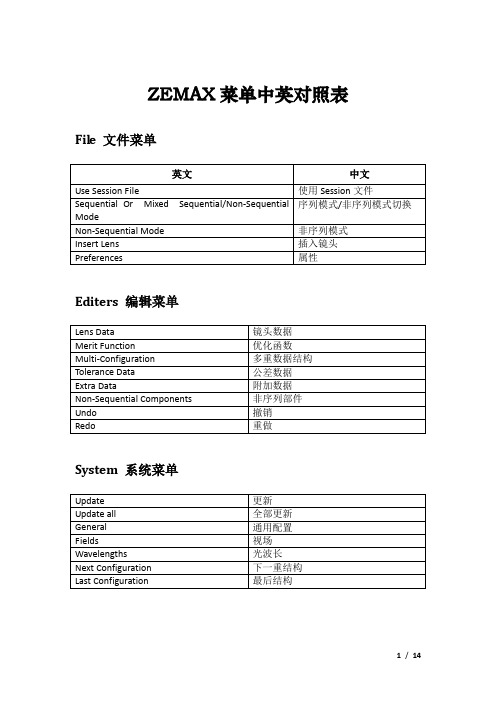
ZEMAX菜单中英对照表File 文件菜单Editers 编辑菜单System 系统菜单Analysis 分析菜单Layout 草图Fans 特性曲线Spot Diagrams 点列图MTF (Modulation Transfer Function) 传递函数PSF (Point Spread Function) 点扩散函数Wavefront 波前Surface 曲面RMS 均方根Encircled Enegry 能量分布Illumination 照度Image Analysis 像分析Biocular Analysis 双目分析Miscellaneous 杂项Aberration Coefficients 像差失真系数Calculations 计算Glass and Gradient Index 玻璃和梯度折射率Universal Plot 通用图表Polarization 偏振Coatings 镀膜Physical Optics 物理光学Tools 工具菜单Optimization 优化Tolerancing 公差Test Plates 样板Catalogs 目录Coatings 镀膜Scattering 散射Apertures 光圈Fold Mirrors 折叠反射镜Export Data 导出数据Miscellaneous 杂项Reports 报告菜单Macros 宏指令菜单Extensions 外部扩展菜单Help 帮助菜单ZEMAX词汇表缩写鉴别转换功效Modulation Transfer Function光点图(spot diagrams)光扇图(ray fan)光程差图光学调制传递函数(modulation transfer function,MTF)点扩散函数(point spread function,PSF) 图包围圆(encircled)包围矩形(ensquared) 的能量信息、像差计算( 塞德(Seidel)泽尼克(Zernike) )、理想或偏斜(skew) 高斯光束参数计算、极化描光波前传播工具。

了解ZEMAX不计算光栅衍射效率,所以不能设置闪耀光栅。
ZEMAX中光栅相关的有:类型(全息或者刻划)、刻线数、衍射级次、基底面型(平面、凹面或者环面等)。
只有将光栅后面的光学元件摆对位置,ZEMAX才会将衍射光线画出来。
所以需要用好坐标断点和solve中的chief ray。
Diffraction Grating______<ZEMAX序列241>The diffraction grating surface can be used to model straight-line ruled gratings. The grating lines are parallelto the local x-axis. Other orientations can be simulated by using a coordinate break surface before and after thegrating surface(在序列模式中由于没有非序列中的旋转选项,所以需要用到坐标断点面). For a plane grating, rays traced to the grating are refracted according to the equationwhere d is the grating spacing (always in micrometersμm), θ2 is the refracted angle, θ1 is the incident angle, Mis the diffraction order, λis the wavelength (always in micrometersμm), n1and n2are the indices of refraction beforeand after the grating(透射式光栅的n1and n2该如何确定), and T is the grating frequency in lines per micrometer. Note that the sign convention for Mis completely arbitrary. ZEMAX uses the definition for T (lines per micrometer) rather than d (micrometers perline). The grating surface can be plane, spherical, or conical, and the medium before the grating, as well as thegrating itself, can be air, glass, "MIRROR" or any other valid glass type. The grating is described by the y-spacingof the grating lines measured in lines per micrometer (independent of the system units) and the diffraction order.ZEMAX only models gratings to the extent of deviating ray paths. Other properties, such as efficiency, and relativetransmission are not supported. If the grating spacing is too small (or if T is too large) to satisfy the grating relation,then a "Ray missed surface" error will be reported.Standard Lens______<ZEAMX323>The standard lens is a lens composed of standard ZEMAXsurfaces. Standard surfaces may be planes, spheres, conicaspheres,or hyperhemispheres.The standardlens is composed of5 separate sections:1) A standard shape front face.2) A standard shape rear face.3) An annular ring between the clearaperture of the front faceand the edge of thefront face.4) An annular ring between the clearaperture of the rear faceand the edge of therear face.5) A possibly tapered cylindrical surfaceconnecting the edgesof the front and rear faces of the lens.9 parameters are used to define a standard lens:1) The radius of curvature of the front face. Use zero for infinity (flat).2) The conic constant of the front face.3) The semi-diameter to the clear aperture of the front face. Use a negative value to yield the hyperhemisphericsag point.4) The radial aperture to the edge of the front side of the lens.5) The center-to-center thickness of the lens.6) The radius of curvature of the rear face. Use zero for infinity (flat).7) The conic constant of the rear face.8) The semi-diameter to the clear aperture of the rear face. Use a negative value to yield the hyperhemisphericsag point.9) The radial aperture to the edge of the rear side of the lens.All5surfaces may refract, reflect, or absorb light, depending upon the material properties.The reference point is the center of the front face of the lens. Coating/Scatter Groups: Front face CSG #1,back face CSG #2, all other faces CSG #0.Diffraction Grating_________<ZEMAX307>The diffraction grating is very similar to a Standard Lens, with 2additional parameters:1-9: See the Standard Lens description for information on theseparameters.10: The grating line frequency in lines/micrometer onthe frontface.11: The diffraction order for the front face.The grating is assumed to consist ofequally spacedlinesparallel to the local x axis. The grating frequency isthe lines permicrometer along the y direction;projected down on to the surface.This object does not diffract rays correctly if the front diffractivesurfaceis made hyperhemispheric.For important information on diffractive objects, see “Diffraction from NSC objects” on page 347.Coating/Scatter Groups: Front face CSG #1, back face CSG #2, all other faces CSG #0.Rectangular Pipe Grating_______<ZEMAX320>This object is the same shape as the Rectangular Pipe and uses the same first 9 parameters. However, thegrating version adds a linear diffraction grating on all four sides. There are two additionalparameters:10: The grating line frequency inlines/micrometer on the side faces.11: The diffraction order. Multipleorders may be specified, see “Diffractiontab” on page 350.The grating consists of equallyspaced lines perpendicular to the local zaxis, lying on each of the four faces.Thegrating frequency is the lines permicrometer along the z direction;projected down on to either the XZ orYZplane. Note the grating exists on all four sides of the pipe. The reference point is the center of the front open face.For important information on diffractive objects, see “Diffraction from NSC objects” on page 347.Coating/Scatter Groups: All faces CSG #0.Rectangular Volume Grating_______<ZEMAX322>This object is the same shape as the Rectangular Volume and uses the same first 9 parameters. However, thegrating version adds a linear diffraction grating on four faces of the object: the top, bottom, left,and right faces.There is no grating on the front or backfaces. There are two additional parameters:10: The grating line frequency inlines/micrometer on the side faces.11: The diffraction order. Multipleorders may be specified, see “Diffraction tab”on page 350.The grating consists of equally spacedlines perpendicular to the local z axis, lyingon each of the four faces.The gratingfrequency is the lines per micrometer along the z direction; projected down on to either the XZ or YZplane. Note the grating exists on all four sides of the volume. The reference point is the center of the front face.For important information on diffractive objects, see “Diffraction from NSC objects” on page 347.Coating/Scatter Groups: Front face CSG #1, back face CSG #2, all other faces CSG #0.Diffraction from NSC objects———《ZEMAX347》Some NSC objects have one or more diffractive faces; such as the Diffraction Grating, Binary 1, and Binary 2objects. These objects refract or reflect rays as well as diffract them, according to the grating period or phase andthe diffraction order and wavelength. For any ray, if the diffraction order being traced does not satisfy the gratingequation, then the energy of that ray will refract or reflect along the zero order path.Ray splitting is supported on diffractive surfaces, but splitting is only allowed by order and not by reflected andtransmitted Fresnel coefficients. For this reason, no "ghost" rays are generated from diffractive surfaces.All diffractive NSC objects support a parameter to defined the "order" for diffraction from the object. This orderis called the "primary" diffraction order. Sequential rays which enter the non-sequential group through the entryport will diffract only along the primary order.Rays which originate from a non-sequential source will diffract only along the primary order if ray splitting isoff. If ray splitting is on, then the diffraction may be optionally controlled by the settings on the "Diffraction" tab ofthe Object Properties dialog box. This tab includes optional settings which will split the ray by order; allowing morethan one diffraction order to be simultaneously traced.For more information on diffraction, see “Diffraction tab” on page 350.The object properties dialog box---Diffraction tab《ZEMAX350》For important information that applies to all diffractive objects, see “Diffraction from NSC objects” on page 347.The Diffraction tab is used to define the properties of diffractive surfaces. The tab supports the followingcontrols:Split: Selects how rays are split off from diffractive surfaces. The options are:Don’t split by order: The rays will not split at the surface. Only the or der defined by the object parameterswill be traced, and all the transmitted energy goes into this one order.Split by table below: A user defined number of rays will be traced over a range of integral orders. The fractionof energy given to each order is defined by the user in a table.Split by DLL function: An external DLL program is used to define which orders are traced, how much energyeach order is given, and optionally, what the output ray properties are (for user defined diffraction所有这些被选用的级次所对应的小数部分的和为1,若不是则检测器上不会显示任何结果). For moreinformation on defining Diffraction DLLs, see page 361.DLL: The name of the DLL to use. This DLL must be placed in the \DLL\DIFFRACT subdirectory of the\OBJECTS directory. See “Directories” on page 59.Start/Stop order: The beginning and ending order number. These numbers determine how many cells in thetable are active; and how many times the DLL will be called to compute the output ray properties.Remaining controls: The remaining controls are used to define the parameters to be passed to the DLL. Tomake these parameters variable or under multi-configuration control, use the NPRO operand; for details see“NPRO” on page 473.备注:1.在看文献时,经常看到实验结果图中,其纵轴通常不是损耗单位,数据也是经过处理的,标以a.u.。

ZEMAX概况ZEMAX是一套综合性的光学设计软件。
它集成了光学系统所有的概念、设计、优化、分析、公差分析和文档整理功能。
具有直观、功能强大、灵活、快速、容易使用等优点。
3种不同的版本:SE, XE,和EE。
ZEMAX可以模拟Sequential和non-sequential成像系统和非成像系统。
序列性(Sequential)光线追迹大多数成像系统都可以由一系列顺序排列的光学面来描述。
光线按面的顺序进行追迹。
如相机镜头、望远镜镜头、显微镜头等。
它有很多优点,如光线追迹速度快、可以直接优化和进行公差预算。
ZEMAX中的光学面可以是反射面、折射面或衍射面。
也可以建立因为光学薄膜引起的有不同透射率的光学面特性。
面之间的介质可以是各向同性的,如玻璃或空气。
也可以是任意的渐变折射率分布,折射率可以是位置、波长、温度或其它特性参数的函数。
也支持双折射材料,它的折射率是偏振态和光线角度的函数。
ZEMAX中,所有描述面的特性参数,包括形状、折射、反射、折射率、渐变折射率、热系数、透射率和衍射率都可以自定义。
非序列性(Non-sequential)光线追迹很多重要的光学系统不能用sequential光线追迹的模式描述,如复杂的棱镜、光管、照明系统、小面反射镜、非成像系统或任意形状的物件等。
而且散射和杂光也不能用序列性分析的模式。
这些系统要求用non-sequential模式,此时光线以任意的顺序打到物件上。
Non-sequential模式可以对光线传播进行更细节的分析,包括散射光或部分反射光。
进行non-sequential追迹时,ZEMAX用3D solid models光学元件,可以是任意的形状。
支持散射、衍射、渐变折射率、偏振和薄膜。
用光度学和辐射度学的单位。
Sequential 和non-sequential系统ZEMAX还可以在同一个系统中使用sequential和non-sequential光线追迹模式。

Zemax光学设计:ZEMAX中的初级像差描述引言:实际的光学系统都是不完美的,光线经过光学系统各个表面的传输都会形成多种像差。
光学设计的一个重要任务就是校正、优化与平衡这些像差,使成像质量达到技术要求。
常见的初级像差包括5种单色像差(球差、彗差、像散、场曲与畸变)和2种色差(轴向色差与倍率色差)。
1.ZEMAX中的球差描述以一个简单的单透镜为例。
首先输入系统特性参数,如下:在系统通用对话框中设置孔径。
在孔径类型中选择“Entrance Pupil Diameter”,并根据设计要求输入“50.0”;在视场设定对话框中设置1个视场,要选择“Angle”,如下图:在波长设定对话框中,设定0.55um一个波长,如下图:LDE的结构参数,如下图:查看2D Layout:查看Ray Fan:Ray Fan图中可以定量分析球差在不同孔径的大小,可以看出球差曲线具有旋转对称性;而且由于不存在离焦的情况,其在中央区域很平坦。
查看点列图:可以看出,不同环带(孔径)的光线会聚于光轴的不同点。
球差是和孔径相关的像差。
查看波前图:从光程差上分析,球差的产生其实是波前相位的移动,即出瞳参考球面与实际球面波前的差异。
当实际波前和参考波前分离时,光程差不再相等,这样物面同一束光经实际透镜和理想透镜后,相当于产生了牛顿干涉环。
查看Seidel Coefficients:也可以在MFE中使用操作数查看球差值。
Surf若不指定某一个面(取值为0),则计算所有面产生球差总和。
2.ZEMAX中的彗差描述使用一个带Binary 2面型的单透镜来模拟彗差。
首先输入系统特性参数,如下:在系统通用对话框中设置孔径。
在孔径类型中选择“Entrance Pupil Diameter”,并根据设计要求输入“20.0”;在视场设定对话框中设置1个视场,要选择“Angle”,如下图:在波长设定对话框中,设定0.55um一个波长,如下图:LDE的结构参数,如下图:查看2D Layout:查看Ray Fan:Ray Fan图显示彗差为主要像差,残余还有离焦和球差。
概述这篇文章介绍了如何在OpticStudio中建立衍射光学表面以及如何使用Binary2(二元面2)模拟衍射光学元件。
本文使用的示例文件请从以下链接下载:https:///support/knowledgebaxxxxse/Knowledgebaxxxxse-Attachments/How-to-Design-Diffractive-Optics-Using-the-Binary/How-to-use-Binary-2.aspxBinary2面型Zemax LLC感谢Optics1公司的Robert E.Fischer先生授权使用其著作《Optical System Design》中的图表。
在OpticStudio中,许多表面除了可以定义折射光焦度以外,还可以定义衍射光焦度。
衍射光焦度与材料折射率和表面矢高无关,但可以改变光的相位。
有关建立衍射光学表面的详细信息,请参考我们的往期文章“OpticStudio建模衍射表面”。
Binary2中的衍射光焦度会在光学表面的截面上引入连续的相位变化:其中系数Ai的单位为弧度。
由于相位变化在表面的截面上是连续的,因此Binary2面型模拟的是一个理想的二元衍射元件,其二元面的台阶尺寸趋近于无穷小或小于光的波长。
通常来讲,Binary2面型模拟衍射光学元件的环形衍射区 (Diffraction Zones) 的尺寸与该区域到表面顶点的径向距离有关,如下图所示。
OpticStudio可以自动计算每个环形衍射区的径向坐标使相邻区域的相位差为2π。
Figure 13.5 from Optical System DesignBinary2面型在固定径向坐标处所引入的附加相位与波长无关。
与波长相关的光程由下式给出:下图布局图所示为Binary2的色差:Binary2消色差单透镜Binary2面型经常用来矫正色差。
在一个简单的单透镜中,长波长光的焦距相比短波长的光更长,如下图(a)。
zemax binary phase 相位摘要:1.简介2.Zemax Binary Phase 相位的应用3.Zemax Binary Phase 相位的原理4.Zemax Binary Phase 相位的使用方法5.Zemax Binary Phase 相位的优势和局限6.总结正文:Zemax 是一款光学设计软件,广泛应用于光学系统的建模、分析和优化。
在Zemax 中,Binary Phase 相位是一个重要的工具,能够帮助用户精确地控制光学系统的相位特性。
Binary Phase 相位在Zemax 中的主要应用是设计和优化相位阵列透镜、光束整形器等光学元件。
通过调整Binary Phase 相位的参数,用户可以实现对光的传播方向、波前形态和相位的精确控制,从而满足不同光学系统的需求。
Zemax Binary Phase 相位的原理主要基于光的干涉现象。
在Binary Phase 相位中,通过在光学元件表面引入周期性的相位调制,可以实现对光的相位控制。
这种相位调制可以通过数字化生成,具有高度的可编程性和灵活性。
在Zemax 中使用Binary Phase 相位的方法如下:首先,用户需要在软件中定义Binary Phase 相位的参数,包括相位调制周期、幅度等。
然后,将这些参数应用到光学元件的表面,从而实现对光的相位控制。
最后,通过优化光学系统的性能指标,如传输效率、光束质量等,来达到设计目标。
Zemax Binary Phase 相位具有许多优势,如高度可编程、灵活的相位控制能力,能够满足各种光学系统的需求。
然而,它也存在一些局限,如对光学元件的制作工艺要求较高,可能需要特殊的加工技术来实现。
综上所述,Zemax Binary Phase 相位是一个强大的工具,能够帮助用户精确地控制光学系统的相位特性。
ZEMAX光学设计软件操作说明详解找到一些资料希望对大家有用!【ZEMAX光学设计软件操作说明详解】介绍这一章对本手册的习惯用法和术语进行说明。
ZEMAX使用的大部分习惯用法和术语与光学行业都是一致的,但是还是有一些重要的不同点。
活动结构活动结构是指当前在镜头数据编辑器中显示的结构。
详见“多重结构”这一章。
角放大率像空间近轴主光线与物空间近轴主光线角度之比,角度的测量是以近轴入瞳和出瞳的位置为基准。
切迹切迹指系统入瞳处照明的均匀性。
默认情况下,入瞳处是照明均匀的。
然而,有时入瞳需要不均匀的照明。
为此,ZEMAX支持入瞳切迹,也就是入瞳振幅的变化。
有三种类型的切迹:均匀分布,高斯型分布和切线分布。
对每一种分布(均匀分布除外),切迹因素取决于入瞳处的振幅变化率。
在“系统菜单”这一章中有关于切迹类型和因子的讨论。
ZEMAX也支持用户定义切迹类型。
这可以用于任意表面。
表面的切迹不同于入瞳切迹,因为表面不需要放置在入瞳处。
对于表面切迹的更多信息,请参看“表面类型”这一章的“用户定义表面”这节。
后焦距ZEMAX对后焦距的定义是沿着Z轴的方向从最后一个玻璃面计算到与无限远物体共轭的近轴像面的距离。
如果没有玻璃面,后焦距就是从第一面到无限远物体共轭的近轴像面的距离。
基面基面(又称叫基点)指一些特殊的共轭位置,这些位置对应的物像平面具有特定的放大率。
基面包括主面,对应的物像面垂轴放大率为+1;负主面,垂轴放大率为-1;节平面,对应于角放大率为+1;负节平面,角放大率为-1;焦平面,象空间焦平面放大率为0,物空间焦平面放大率为无穷大。
除焦平面外,所有的基面都对应一对共轭面。
比如,像空间主面与物空间主面相共轭,等等。
如果透镜系统物空间和像空间介质的折射率相同,那么节面与主面重合。
ZEMAX列出了从象平面到不同象方位置的距离,同时也列出了从第一面到不同物方平面的距离。
主光线如果没有渐晕,也没有像差,主光线指以一定视场角入射的一束光线中,通过入瞳中央射到象平面的那一条。
ZEMAX光学设计软件操作说明详解找到一些资料希望对大家有用!【ZEMAX光学设计软件操作说明详解】介绍这一章对本手册的习惯用法和术语进行说明。
ZEMAX使用的大部分习惯用法和术语与光学行业都是一致的,但是还是有一些重要的不同点。
活动结构活动结构是指当前在镜头数据编辑器中显示的结构。
详见“多重结构”这一章。
角放大率像空间近轴主光线与物空间近轴主光线角度之比,角度的测量是以近轴入瞳和出瞳的位置为基准。
切迹切迹指系统入瞳处照明的均匀性。
默认情况下,入瞳处是照明均匀的。
然而,有时入瞳需要不均匀的照明。
为此,ZEMAX支持入瞳切迹,也就是入瞳振幅的变化。
有三种类型的切迹:均匀分布,高斯型分布和切线分布。
对每一种分布(均匀分布除外),切迹因素取决于入瞳处的振幅变化率。
在“系统菜单”这一章中有关于切迹类型和因子的讨论。
ZEMAX也支持用户定义切迹类型。
这可以用于任意表面。
表面的切迹不同于入瞳切迹,因为表面不需要放置在入瞳处。
对于表面切迹的更多信息,请参看“表面类型”这一章的“用户定义表面”这节。
后焦距ZEMAX对后焦距的定义是沿着Z 轴的方向从最后一个玻璃面计算到与无限远物体共轭的近轴像面的距离。
如果没有玻璃面,后焦距就是从第一面到无限远物体共轭的近轴像面的距离。
基面基面(又称叫基点)指一些特殊的共轭位置,这些位置对应的物像平面具有特定的放大率。
基面包括主面,对应的物像面垂轴放大率为+1;负主面,垂轴放大率为-1;节平面,对应于角放大率为+1;负节平面,角放大率为-1;焦平面,象空间焦平面放大率为0,物空间焦平面放大率为无穷大。
除焦平面外,所有的基面都对应一对共轭面。
比如,像空间主面与物空间主面相共轭,等等。
如果透镜系统物空间和像空间介质的折射率相同,那么节面与主面重合。
ZEMAX列出了从象平面到不同象方位置的距离,同时也列出了从第一面到不同物方平面的距离。
主光线如果没有渐晕,也没有像差,主光线指以一定视场角入射的一束光线中,通过入瞳中央射到象平面的那一条。
矿产资源开发利用方案编写内容要求及审查大纲
矿产资源开发利用方案编写内容要求及《矿产资源开发利用方案》审查大纲一、概述
㈠矿区位置、隶属关系和企业性质。
如为改扩建矿山, 应说明矿山现状、
特点及存在的主要问题。
㈡编制依据
(1简述项目前期工作进展情况及与有关方面对项目的意向性协议情况。
(2 列出开发利用方案编制所依据的主要基础性资料的名称。
如经储量管理部门认定的矿区地质勘探报告、选矿试验报告、加工利用试验报告、工程地质初评资料、矿区水文资料和供水资料等。
对改、扩建矿山应有生产实际资料, 如矿山总平面现状图、矿床开拓系统图、采场现状图和主要采选设备清单等。
二、矿产品需求现状和预测
㈠该矿产在国内需求情况和市场供应情况
1、矿产品现状及加工利用趋向。
2、国内近、远期的需求量及主要销向预测。
㈡产品价格分析
1、国内矿产品价格现状。
2、矿产品价格稳定性及变化趋势。
三、矿产资源概况
㈠矿区总体概况
1、矿区总体规划情况。
2、矿区矿产资源概况。
3、该设计与矿区总体开发的关系。
㈡该设计项目的资源概况
1、矿床地质及构造特征。
2、矿床开采技术条件及水文地质条件。