凌华控制板卡使用方法精编版
- 格式:ppt
- 大小:1.12 MB
- 文档页数:20

PCI-1710快速安装使用手册PCI-1710快速安装使用手册 (1)第一章产品介绍 (2)1.1 概述 (2)1.1.1 即插即用功能 (2)1.1.2 单端或差分混合的模拟量输入 (2)1.1.3 卡上FIFO(先入先出)存储器 (2)1.1.4 卡上可编程计数器 (2)1.1.5 用于降低噪声的特殊屏蔽电缆 (2)1.1.6 16路数字输入和16路数字输出 (3)1.1.7 短路保护 (3)1.2 特点: (3)1.3 一般特性: (3)第二章安装与测试 (3)2.1 初始检查 (3)2.2 Windows2K/XP/9X下板卡的安装 (4).1 软件的安装: (6)2.2.2 硬件的安装: (7)2.3 测试 (8)2.3.1 模拟输入功能测试 (8)2.3.2 模拟输出功能测试 (9)2.3.3 数字量输入功能测试 (10)2.3.4 数字量输出功能测试 (11)2.4.5 计数器功能测试 (12)第三章信号连接 (13)3.1 模拟信号输入连接: (15)3.1.1 单端模拟输入连接 (15)3.1.2 差分式模拟输入连接 (15)模拟信号输出连接 (17)触发源连接 (17)3.3.1 内部定时器触发连接 (17)3.3.2 外部触发源连接 (18)第四章例程使用详解 (18)4.1 板卡支持例程列表4.2 常用例子使用说明 (18)4.2.1 ADSOFT/ADTRIG(软件触发方式例程) (18)4.2.2 ADint(中断方式进行数据采集的例程) (19)4.2.3 DIGOUT(数字量输出): (21)4.2.4 COUNTER(计数程序) (23)4.2.5 Digin (数字量输入例程) (24)4.2.6 PULSE(脉冲输出例程) (24)4.2.7 MADint(多通道中断采集例程) (25)第五章遇到问题,如何解决? .................. 错误!未定义书签。
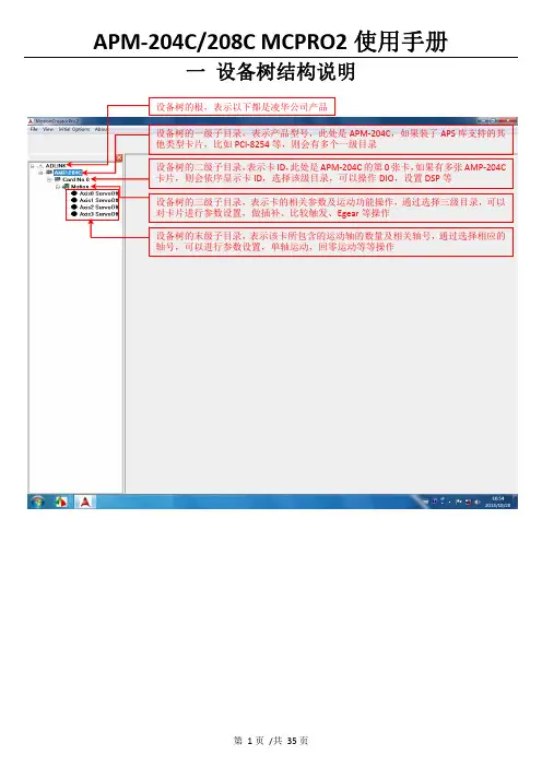
一 设备树结构说明二 设备树目录对应的菜单项及工具栏2.1 根目录及一级子目录(AMP ‐204C 子目录)2.1.1 对应菜单1、Initial Options 菜单项2、About 菜单项该菜单项用于获取MCPRO2版本信息、数据库版本信息及MCPRO2所支持的产品信息等等。
3、根目录右键菜单当选择ADLINK 根目录,右键点击,弹出保存/载入所有参数菜单,如下所示2.2 二级子目录(Card No 0子目录)2.2.1对应菜单及工具栏当选中相应的卡ID 目录(例如Card No 0),会弹出如下DIO 和DSP 操作菜单及工具栏2.2.2 右键菜单当选中相应的卡ID2.3 三级子目录(Motion 子目录)2.3.1对应工具栏2.3.2对应菜单栏2.3.3 右键菜单当选中相应卡ID 目录(例如Card No 0)下的Motion ,右击 会弹出如下右键菜单ServoOn 该卡下面的所有轴ServoOff 该卡下面的所有轴2.4 末级子目录(单轴操作子目录)2.4.1对应工具栏当选中相应的轴号时,会弹出如下工具栏2.4.2对应菜单栏2.4.3 右键菜单三 MCPRO2操作3.1 设置向导(SetupWizard )选择要操作的轴,在工具栏点击SetupWizard 按钮,弹出SetupWizard 对话框。
如下图示。
Step 1:Control Mode (控制模式)该步骤用于设置板卡控制模式及伺服更新率。
但是为防止客户误操作,控制模式设置和伺服更新率设置被移出该步骤。
如果要设置,请参考下面的设置。
1、选择要操作的轴2、点击SetupWizard按钮3、弹出SetupWizard对话框1、更改控制模式:注意:请根据每个轴使用的电机类型来设置每个轴的控制模式,控制模式一旦设定,请勿随意变更。
1、先选择Motion 子目录点击此按钮保存设置2、设置伺服更新率:以下两种方式都可以设置伺服更新率: 方式1:方式2:注意:如非必要,请勿随意更改伺服更新率。
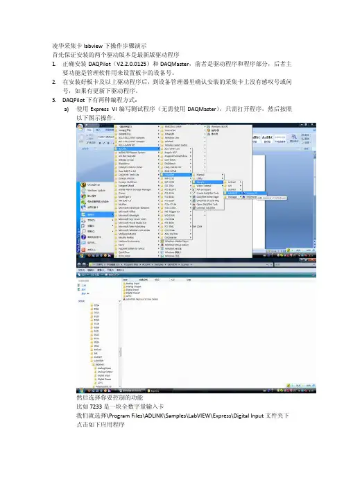
凌华采集卡labview下操作步骤演示首先保证安装的两个驱动版本是最新版驱动程序1.正确安装DAQPilot(V2.2.0.0125)和DAQMaster,前者是驱动程序和程序部分,后者主要功能是管理软件用来设置板卡的设备号。
2.在安装好板卡及以上驱动程序后,到设备管理器里确认安装的采集卡上没有感叹号或问号,如果有更新下驱动程序。
3.DAQPilot下有两种编程方式:a)使用Express VI编写测试程序(无需使用DAQMaster),只需打开程序,然后按照以下图示操作。
然后选择你要控制的功能比如7233是一块全数字量输入卡我们就选择\Program Files\ADLINK\Samples\LabVIEW\Express\Digital Input文件夹下点击如下应用程序选择如下图显示程序框图可以看到程序面版如下然后双击中间的模块如下:点击Modify进行配置类似如下示图然后一直点击Next,直到Finish然后点击labview环境运行按钮,数据就会出现在前面板的表格里。
b)使用Polymorphic VI编写程序,需要首先配置DAQMaster,操作如下图:点击打开后,还需点击几个图标左上角的展开图标和带红色字母A的图标就会显示主机里安装的所有板卡了,我的电脑里没有板卡,所以只显示了一个虚拟设备,且设备号是Dev0,此设备号就是我们需要为板卡设置的,我们在Dev0上右键点击选择Edit,出现如下图假如我们机器里差了块7233我们可以重新起个名字例如Dev1.然后点击确定。
此时DAQMaster工作就做玩了。
我们打开测试程序此时我们选择多态程序。
选择Digital IO Samples.llb里的如下程序我们把里面默认的Dev0改成我们刚在DAQMaster里设置的Dev1,然后把后面的通道可以改成0:31,同时可以把指示灯拉长也变成32个。
如下图然后点击左上角运行图标,程序就可以运行了。

英贝特航天科技 HT-5138 凌动通用主板使用说明书HT-5138Atom凌动通用主板使用说明书中国航天科工集团三院8357研究所天津市英贝特航天科技有限公司英贝特航天科技 HT-5138 凌动通用主板使用说明书在打开包装盒后请首先依据物件清单检查配件若发现物件有所损坏或是有任何配件短缺的情况请尽快与您的经销商联络¾ 1 块HT-5138工业级CPU 卡¾ 1 本用户手册¾ 1 张驱动光碟¾ 配套电缆包声明除列明随产品配置的配件外,本手册包含的内容并不代表本公司的承诺。
本公司保留对此手册更改的权利且不另行通知。
对于任何因安装使用不当而导致的直接间接有意或无意的损坏及隐患概不负责。
订购产品前请向经销商详细了解产品性能是否符合您的需求。
本手册所涉及到的其他商标其所有权为相应的产品厂家所拥有。
本手册内容受版权保护版权所有未经许可不得以任何方式进行复制。
安全使用小常识1. 产品使用前请您务必仔细阅读产品说明书2. 对未准备安装的板卡应将其保存在防静电保护袋中3. 在从防静电保护袋中拿出板卡前应将手先置于接地金属物体上一会儿比如10 秒钟以释放身体及手中的 静电4. 在拿板卡时需戴静电保护手套并且应该养成只触及其边缘部分的习惯5. 为避免人体被电击或产品被损坏请在每次对主板板卡进行拔插或重新配置时先关闭电源并将电源线从电源插座中拔掉6. 在需对板卡或整机进行搬动前请务必先将电源线从电源插座中拔掉7. 对整机产品当需增加减少板卡时请务必先拔掉电源8. 当您需连接或拔除任何设备前请确定所有的电源线事先已被拔掉9. 应避免频繁开、关机,每次关机后应至少等待30 秒后再开机目 录第一章 产品介绍 (4)简介 (4)环境与机械尺寸 (4)微处理器(CPU) (4)芯片组(Chipset) (4)系统存储器(System Memory) (5)IDE 功能 (5)显示功能 (5)网络功能(LAN) (5)USB 功能 (5)I/O 功能 (5)BIOS (5)电源要求 (5)省电特性 (5)总线扩展接口 (6)Watchdog 功能 (6)产品功能原理示意图 (6)第二章 物理特性 (7)2.1 主要元器件位置图 (7)2.2 跳线功能设置 (8)2.3 连接器信号定义 (9)VGA接口 (9)串行接口 (9)LCD逆变器电源接口 (10)USB接口 (10)键盘与鼠标接口 (11)LPC插座 (11)LVDS接口 (12)SMBUS插座 (12)前面板控制引线插座 (12)+12V电源插座 (13)第三章 BIOS 功能简介 (13)进入设定 (13)高级BIOS功能 (15)高级芯片组功能 (15)附录 (17)Watchdog 编程指引 (17)第一章 产品介绍简介HT-5138是一款基于Intel® Atom™ N270处理器设计的低功耗、高性能、加固通用主板其主要特点如下:板载Intel®Atom™ N270超低功耗处理器,主频1.6GHz(FSB 533MHz)采用Intel945GSE+ICH7M芯片组; 提供一条200Pin SO-DIMM系统内存插槽,最高支持DDRII400/533 2G内存容量; 支持CRT、LVDS等显示接口输出; 可支持2个标准RS-232接口,其中一个支持RS-485/RS-422接口(与COM2共用端口);板载4G SSD,最大可支持8G; 此外,HT-5138还提供2个千兆网络接口、2路标准SATA硬盘接口、1个IDE接口、 6个USB2.0高速接口、1个PS/2鼠标/键盘接口、音频输入/输出接口、1个LPC接口、PC/104+扩展总线以及看门狗定时器等功能。
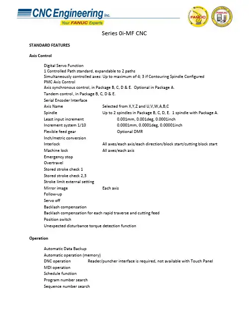
Series 0i-MF CNCSTANDARD FEATURESAxis ControlDigital Servo Function1 Controlled Path standard, expandable to2 pathsSimultaneously controlled axes: Up to maximum of 4; 3 if Contouring Spindle ConfiguredPMC Axis ControlAxis synchronous control, in Package B, C, D & E. Optional in Package A.Tandem control , in Package B, C, D & E.Serial Encoder InterfaceAxis Name Selected from X,Y,Z and U,V,W,A,B,CSpindle Up to 2 spindles in Package B, C, D, E. 1 spindle with Package A.Least input increment 0.001mm, 0.001deg, 0.0001inchIncrement system 1/10 0.0001mm, 0.0001deg, 0.00001inchFlexible feed gear Optional DMRInch/metric conversionInterlock All axes/each axis/each direction/block start/cutting block start Machine lock All axes/each axisEmergency stopOvertravelStored stroke check 1Stored stroke check 2,3Stroke limit external settingMirror image Each axisFollow-upServo offBacklash compensationBacklash compensation for each rapid traverse and cutting feedPosition switchUnexpected disturbance torque detection functionOperationAutomatic Data BackupAutomatic operation (memory)DNC operation Reader/puncher interface is required, not available with Touch PanelMDI operationSchedule functionProgram number searchSequence number searchSequence number comparison and stopProgram restartManual intervention and returnRetraction for rigid tappingBuffer registerDry runSingle blockJOG feedManual reference position returnReference position setting without DOGReference position setting with mechanical stopperReference position shiftManual handle feed Max. 3 units (requires MPG - order from I/O Tab)Manual handle feed rate x1, x10, xm, xn m: 0~127, n: 0~1000 Manual handle interruptionIncremental feed x1, x10, x100, x1000Jog and handle simultaneous modeInterpolationPositioning G00 (Linear interpolation type positioning is possible)Single direction positioning G60Exact stop mode G61Exact stop G09Linear interpolationCircular interpolation Multi-quadrant is possibleDwell Dwell in secondsDwell per revolution (synchronous cutting function is required.) Cylindrical interpolationHelical interpolation Circular interpolation plus max. 2 axes linear interpolationSkip G31High-speed skip Input signal is 4 pointReference position return G28Reference position return check G272nd reference position return3rd/4th reference position returnNormal direction control Standard in Package B, C, D & E. Optional in Package A.Index table indexingGeneral purpose retractNano InterpolationFeed FunctionRapid traverse rate Max. 240m/mi n (1μm)Max. 100m/min (0.1μm)Rapid Traverse Feedrate Override F0, 25, 50, 100% or 0~100%(1% Step)Feed per minuteFeed per revolutionTangential speed constant controlCutting feedrate clampAutomatic acceleration/deceleration Rapid traverse: linear; Cutting feed: exponential, linear Rapid traverse bell-shaped acceleration/decelerationLinear acceleration/deceleration after cutting feed interpolationFeedrate override 0~254%One-digit F code feedJog override 0~655.34%Override cancelCutting modeTapping modeRapid traverse block overlapExternal decelerationAI advanced preview controlProgrammingProgram code EIA RS244/ISO840Label skipParity check Horizontal and vertical parityControl in/outOptional block skip 9 LevelsMax. programmable dimension ±8-digitProgram file name 32 charactersExternal memory and sub program calling functionSequence number N5-digitAbsolute/incremental programming Combined use in the same blockDecimal point programming / pocket calculator type decimal point programmingInput unit 10 time multiplyPlane selection G17, G18, G19Rotary axis designationRotary axis roll-overPolar coordinate commandCoordinate system settingAutomatic coordinate system settingWorkpiece coordinate system G52~G59Workpiece coordinate system presetAddition of workpiece coordinate system pair 48 pairsDirect input of workpiece origin offset value measuredManual absolute on and offOptional chamfering/corner RProgrammable data input G10Sub program call 10 folds nestedCustom macroAddition of custom macro common variables #100~#199, #500~#999 Pattern data inputInterruption type custom macroCanned cycles for drillingSmall-hole peck drilling cycleCircular interpolation by R programmingAutomatic corner overrideAutomatic corner decelerationFeedrate clamp based on arc radiusScalingCoordinate system rotationProgrammable mirror imageTape format for FANUC Series 10/11Auxiliary and Spindle FunctionsAuxiliary function M8-digit2nd auxiliary function B8-digitAuxiliary function lockHigh-speed M/S/T/B interfaceMultiple command of auxiliary function 3Spindle speed function S5-digit, binary outputSpindle serial output S5-digit, serial outputConstant surface speed controlSpindle override 0~254%Spindle orientationSpindle output switching functionSpindle synchronous control Package B, C, D & ERigid tappingTool Functions and Tool CompensationTool Function T8 digitsTool offset pairs ±6 digits 400Tool offset memory C Distinction between geometry and wear, or betweencutter and tool length compensation.Tool length compensationTool offsetTool life managementExtended tool life managementTool length measurementAutomatic tool length measurementPart Program Storage & EditingPart Program Storage 512KBNumber of registerable programs 400Part program editingProgram protectBackground editingExtended part program editingPlaybackPassword functionDisplayStatus displayClock functionCurrent position displayProgram comment display Program name 31 charactersParameter setting and displaySelf-diagnosis functionAlarm displayAlarm history displayOperator message history displayOperation history displayHelp functionRun hour and parts count displayActual cutting feedrate displayDirectory display of floppy cassetteServo setting screenDisplay of hardware and software configurationPeriodic maintenance screenMaintenance information screenTrouble diagnosisSoftware operator's panelSoftware operator's panel general purpose switchEnglish Language Display, Multiple Languages Selectable:Jap,Ger,Fr,Sp,It,Chi,Kor,Por,Dut,Swe,Hun,Cz,Pol,Rus,Tur Data protection key 4 typesErase CRT screen displayData Input/Output and CommunicationsI/O Link i InterfacePunch Panel with 2m Cable: A02B-0236-C192 in LCD Mount, A02B-0120-C192 in Stand Alone.Reader/Punch Interface 1 (RS-232) 2nd Channel may be activated,2nd channel used for Touch ScreenExternal I/O device controlExternal data input: External tool offset External message External machine zero point shift External key inputExternal program inputExternal workpiece number search 9999Expanded external workpiece number searchExternal program number search 1~9999Memory card input/output for maintenancePower Mate CNC managerEmbedded EthernetOtherCD-ROM containing Product Manuals included in the BOM of the Root CNC.Assorted items that vary per Package:24V Power Cable 44C741911-001 CBL +24V M3 TERM-AMP 5M USASpare Fuses: A02B-0236-K100 Fuse, LCD Mount CNCA02B-0319-K100 FUSE, Stand Alone CNC Cable Clamps A02B-0124-K001 CABLE CLAMPSGrounding Bar 44B295864-001 GROUNDING BAR 11 SLOTMiscellaneous Items: A02B-0319-K191 Screw Caps for LCD Mount.A02B-0120-K324 CONNECTOR AND PINSSERIES 0i-MF PACKAGE CHOICES。

DL 系列条屏控制卡使用说明一、概述1.1 简介DL系列脱机条屏控制卡专为条型LED屏幕显示设计。
DL系列控制卡支持计算机能输入的任何字体、内容,支持横向显示和纵向显示。
进入和退出均有多种花样供选择。
部分型号可分区显示时间和字幕,能满足大部分场合的需求。
和同类控制卡相比,该系列卡操作简单,控制面积大,显示花样多,显示稳定。
1.2 各种控制卡所对应的控制软件及参数1.3 DL系列控制卡特色1、专注于条屏类LED控制卡的解决方案,优化设计,简化操作,提高可靠性。
2、设计优化:相比其它条屏控制卡,控制面积大、显示稳定、工作可靠。
3、高可靠性:相比高端的大型控制卡,我们在硬件上采用了同等的接口及驱动芯片,提高了硬件的可靠性;在软件上,我们采用了较低的点频(1.5MHz)、较高的场频(100Hz),可以更稳定地刷新长条屏。
4、操作简化:直接对应最流行的接口及扫描方式,软件设置编辑简单、易用。
1.4 其它约定部分老型号的控制卡由于有更先进的控制卡取代,已经停产,本说明文件不再具体说明。
二、使用说明2.1 DL-B控制卡支持最大64×768尺寸的半户外显示屏,支持时间显示,扫描方式1/4,接口方式通用12接口。
配套软件条屏设置程序V4.01。
2.2 DL-AI支持最大32×512尺寸的半户外显示屏,扫描方式1/4,接口方式通用12接口。
配套软件条屏设置程序V3.01。
2.3 DLTP-2支持最大32×512尺寸的室内显示屏,扫描方式1/16,接口方式通用08接口。
配套软件条屏设置程序V2.08。
2.4 使用注意事项及常见问题解答:1、推荐电源工作电压4.5V-5V,卡最低到4.2V也能工作,但电压越低工作越不可靠。
注意该处的工作电压是指在卡上接线端子处测的电压,由于线压降的原因,卡端子处和开关电源端子处测得的电压有较大差距,电源线长时可能接近1V。
为了保证控制卡的电压不会太低,要注意一下几点:(1)、根据单元板得多少计算电源功率,要保证电源容量足够,一般考虑一块P10单元板按5A电流考虑。

解冻间IFT操作屏使用说明1.主屏幕显示部分➢1: 程序号(5), 程序名(SALAMI80), 调用程序名(ESTUFAJE), 目前运行的子程序序号(11).➢2: 温度值(13.7),温度设定上下限范围(13.0,14.0), 湿度值(79.0), 湿度范围(72.0,80.0).➢3: 其他温度值. 如解冻间, 一般第一个是产品中心温度, 第二个是产品表面温度, 第三个是盘管内温度.➢4: 目前运行工作时间状态. 如TdF表示此子程序的最大持续时间. TmaxL表示最大工作时间, TmaxP表示最大休息时间. 左边白色框内为剩余时间, 右边为设定时间.➢5: 各子菜单名. LIST 主菜单MANUAL 可手动起动项DA TA各项数据PHASE 子程序内容.➢6: 时钟➢7: 工作状态显示.左边是工作状态的时间显示, 右边是各部件起动情况➢8: 设备启动报警显示.➢9: 网络地址操作部分➢F1,F2,F3,F4—对应正上方显示屏显示的内容.➢数字区0~9—为可选择输入数字,小数点及正负号.➢编辑区—M1,M2,M3 为快捷键,可直接启动设备的某些功能。
如一般的设定M1-手动离心风机运行,M2-排风,M3-定时排风。
此项手动运行功能也可在主页面下,按F2(MANUAL)进入。
HELP可以查看各英文缩写的具体含义。
EDIT为编辑键,在需要修改参数时,按此键进行修改。
上下左右箭头可移动光标,或者屏幕,或者数值,或者选择字母等功能。
ESC是退出键。
OK 是确认。
➢报警按钮,当有报警时会有报警声且有灯闪动。
START开机。
STOP关机。
CONT继续。
2.设定程序所有SSC控制面板设定程序的步骤都一样,现以解冻为例第一步按F1 MENU1>Programs 程序2>Alarms报警3>V ersion版本4>Configuration 设置n5>Password密码6>Maintenance维护第二步按1>Programs1>Create/Change program (创建程序)2> Read Program(读程序)3>Program Save(保存程序)4>Program list(程序列表)5>Delete program(删除程序)第三步按1>Create/Change programF1 insert 插入F2 delete 删除F3 list 列表F4 help 帮助第四步按F1 insert第五步选择插入位置,按上下键即可。
LED条屏控制软件操作手册感谢您使用LED条屏控制软件(英文名:led center),LED控制软件是专业LED控制系统配套软件,改软件为绿色软件,不用安装,即复制就可以使用!在使用时,双击该软件就可以了!一:软件配置点击运行软件后,第一次启动时会自动打开“查找显示屏”界面如果没有连接控制卡,会出现如下提示画面:如果多次自动查找失败,请检查串口线是否“交叉电缆”,有没有插好、控制卡是否正常工作注意:严禁在通电的状态下插串口线,请先关掉电源后,再插线。
如果硬件连接正确,软件会自动查找到控制卡,会在软件的主界面上显示控制卡型号及版本号“屏参设置”:步骤:第一步:点击“1号屏”,再点击在右边的主界面的“屏参设置”,如图1所示。
第二步:输入密码“168”点击确定。
第三步:根据显示屏具体参数进行屏参设置。
图3 屏参设置注意,设置过程中如果发现“亮线”请立刻关闭显示屏电源,否则可能烧坏显示屏行管。
第四步:1,如果是户外P10单红的屏,接口是12接口的:屏参为:数据极性:低OE极性:高扫描方式:1/4 扫描,默认4.1扫描方式2,如果是户外P16的屏,接口是12接口的:屏参为:数据极性:低OE极性:高扫描方式:1/4 扫描中的4.3扫描方式3,如果是户内φ3.75,φ5的屏,接口是08接口的:屏参为:数据极性:低OE极性:低扫描方式:1/16 扫描4,如果是车载屏P7.62的屏,接口是08接口的:屏参为:数据极性:低OE极性:低扫描方式:1/8 扫描色彩类型:选择需要显示的屏体颜色,单色或双色。
调整好参数后,点击“设置参数”,在点击“确定”就可以了。
第五步:点击“设置参数”按钮,显示屏参数设置完成。
这样屏体和软件的映射关系设置工作完成。
下面就可以进行节目的编辑和管理工作了。
第六步:分区卡的设置:如果当前卡为分区卡,点击分区进入分区设置画面:可以通过调整红色方框中的上下按键来调整分区的大小。
最多支持3个分区二:控制卡连接:步骤通过工具栏上的“查找屏”功能,就可以自动找到控制卡,图5 所示!图5,查找屏能否找到控制卡,都有提示。
HD2016 LED控制系统操作手册目录4控制卡型录............................................................................................................................ 附录14控制卡选型.......................................................................................................................... 附录1.15第一章概述.......................................................................................................................................5功能特点....................................................................................................................................... 1.15运行环境....................................................................................................................................... 1.26第二章安装与卸载............................................................................................................................6安装............................................................................................................................................... 2.16卸载............................................................................................................................................... 2.27 ........................................................................................................................ 第三章工具使用详解7 ................................................................................................................................... 3.1软件主界面7 ........................................................................................................................................... 3.2标题栏7 ........................................................................................................................................... 3.3菜单栏文件菜单73.3.1 ...............................................................................................................................设置菜单83.3.2 ...............................................................................................................................操作菜单43.3.31 .............................................................................................................................工具51 ..................................................................................................................................... 3.3.4:语言菜单513.3.5 ...........................................................................................................................帮助菜单61: ............................................................................................................................ 3.3.661工具栏......................................................................................................................................... 3.47 ................................................................................................................................. 模拟显示屏13.57 ............................................................................................................................. 13.6显示屏属性栏7 ............................................................................................................................. 13.7遥控器的使用8................................................................................................................ 1智能设置的设置方法.3.81 ..................................................................................................................... 23.9十字屏的设置方法.......................................................................................................... 22. 第四章显示屏节目创建流程224.1新建显示屏文件(第一级内容).............................................................................................22 .................................................... 4.2新建节目(第二级内容,一个显示屏可建1000个节目)32........................................................ 4.3新建分区(第三级内容,每个节目可设置20个分区)3 .......................................................................................................................... :节目制作完成24.4.............................................................................................................. 24 .第五章怎样显示不同内容4 ..................................................................................................................................... 25.1文本显示42图文显示5.2 .....................................................................................................................................525.3动画字显示.................................................................................................................................6 .................................................................................................................................. 2显示5.4E XCEL6 ............................................................................................. 25.5时间显示(万年历时间和表盘)........................................................................................................................... 27.倒时计显示顺5.6/82计数显示5.7 ..................................................................................................................................... 82................................................................................. . 温度或者温湿度显示(需另购感应器)5.8.925.9农历............................................................................................................................................. ............................................................................................................................. 30.第六章通信设置036.1串口线的做法.............................................................................................................................036.2通信设置(串口).....................................................................................................................通讯02323 ........................................................................................................................... 6.2.1通讯13 ........................................................................................................................... 6.2.2 48523网线的做法................................................................................................................................. 6.333通信设置(网口)..................................................................................................................... 6.4)通信-局域网单网络卡(33.E63.................................................................................. 6.4.1 HD)通信局域网多个网络卡(数个-3..................................................................... E6336.4.2 HD.5 ................................................................................................................ 36.5通讯设置(WIFI卡)卡连接单个5 ............................................................................................................... WIFI36.5.1卡连接多个7WIFI3 ............................................................................................................... 6.5.283U盘卡的使用方法...................................................................................................................... 6.6 ....................................................................................................... 40使用过程中的常用设置附录204控制卡如何远程升级........................................................................................................ 附录2.104控制卡如何恢复出厂设置................................................................................................ 附录2.20 .................................................................................................... 4附录2.3控制卡如何测试显示屏1 ............................................................................................................ 4附录2.4显示屏定时开关机142.5附录显示屏指定时间播放........................................................................................................142.6字幕静止不动应该怎么设置............................................................................................ 附录1 ................................................................................................ 字幕连续移动,且不间断4附录2.72 ................................................................................................ 4附录2.8温度与温湿度的操作说明附录1控制卡型录附录1.1控制卡选型控制卡的带载范围与型号,以及控制卡上的接口。
LED视窗图文编辑系统用户使用手册二〇一一年五月目录一、概述................................................ 错误!未定义书签。
1.1、简介............................................................................................................. 错误!未定义书签。
1.2、主要功能特点............................................................................................. 错误!未定义书签。
二、安装................................................ 错误!未定义书签。
2.1、运行环境..................................................................................................... 错误!未定义书签。
2.2、安装及卸载................................................................................................. 错误!未定义书签。
三、制作节目............................................ 错误!未定义书签。
3.1、界面介绍..................................................................................................... 错误!未定义书签。
3.1.1、软件界面........................................................................................... 错误!未定义书签。
1IntroductionThe QorIQ ® LX2160A reference design board (RDB)provides a comprehensive platform that enables design and evaluation of the QorIQ LX2160A processor. The LX2160ARDB comes pre-loaded with a board support package (BSP) based on a standard Linux kernel.The LX2160ARDB functions with an integrated development environment (IDE), such as CodeWarrior DevelopmentStudio. For instructions on how to work with the CodeWarrior Development Studio IDE, see CodeWarrior Development Studio for QorIQ LS series - ARM V8 ISA, Targeting Manual .This document provides details of different board interfaces and explains how to set up and boot the board.2Related documentationThe table below lists and explains the additional documents and resources that you can refer to for more information on the LX2160ARDB.Some of the documents listed below may be available only under a non-disclosure agreement (NDA). To request access to these documents, contact your local NXP field applicationsengineer (FAE) or sales representative.Getting Started GuideRev. 1, 10/2018QorIQ LX2160A Reference Design Board Getting Started GuideContents1Introduction............................................................12Related documentation............................................13Hardware kit contents.............................................24Chassis and board pictures......................................35Power and reset buttons..........................................56Connectors...............................................................67Jumpers...................................................................88LEDs.......................................................................99DIP switches..........................................................1210Getting started with LX2160ARDB.....................1511Ethernet port mapping..........................................2012Flash image layout (2013)Upgrading BSP images inLX2160ARDB.......................................................2114Troubleshooting.. (2215)Revision history (22)3Hardware kit contentsThe table below lists the items included in the LX2160ARDB hardware kit.Apart from the main LX2160ARDB kit, two optional kits are also available for purchase at :•LX2RDBKIT1-10-40: Contains transceivers and cables recommended to be used for testing 10/40 Gigabit Ethernet performance on the LX2160ARDB•LX2RDBKIT2-25G: Contains transceivers and cables recommended to be used for testing 25 Gigabit Ethernet performance on the LX2160ARDBThe table below describes the items included in the LX2RDBKIT1-10-40 kit.The table below describes the items included in the LX2RDBKIT2-25G kit.4Chassis and board picturesThis section provides labelled images of the LX2160ARDB chassis and board for easy identification of different board components. The board components marked with labels are described in the subsequent sections.The figure below shows the front side view of the LX2160ARDB chassis.Power buttonReset buttonEthernet portsFigure 1. LX2160ARDB chassisThe figure below shows the back panel of the LX2160ARDB chassis.Power jackFigure 2. Chassis back panelThe figure below shows the onboard connectors of the LX2160ARDB.P3J3 and J4(hidden)J32J30J42P1J1J2J13J28J14J15J17J16J48BT1J29J50 J52J26 J27J25 J24J46J40 J41 J39 J38J43J37J21J19J18P2J23J53J11J47J22J44 J54 J34J36J45J55J35 J10J5Figure 3. ConnectorsThe figure below shows the jumpers, LEDs, and DIP switches available on the LX2160ARDB.J33(hidden)J6J7J31J57J56J58J8J9D1D13D11D9 and D10D5D39-D28, D44,D45, D43, D42,D27-D24, D41,D23-D18SW4-SW1Figure 4. Jumpers, LEDs, and DIP switchesThe figure below shows a closer look of the DIP switches.SW1SW2SW3SW4Figure 5. DIP switches5Power and reset buttonsThe power and reset buttons are present on the front panel of the LX2160ARDB chassis (see Figure 1). Both power and reset buttons are push buttons. The table below describes the power and reset buttons.You cannot switch off the board completely when the SW_AUTO_ON switch (SW4[2]) is set to ON/1. In this mode, pressing the power switch turns the power off briefly, then it immediately turns back on. To turn off power, set theSW_AUTO_ON switch to OFF/0 or disconnect the AC power.To avoid any damage to SDHC1 port pins due to a silicon erratum, follow these recommendations:•Avoid unplugging the system to power it down; always use the power button on the front panel•If cycling the AC power is needed, keep an SDHC card installed in the slot. Allow Linux to boot and configure EVDD to 1.8 V before removing AC power.6ConnectorsThe LX2160ARDB has numerous onboard connectors (see Figure 3). The table below describes the LX2160ARDB connectors.7JumpersJumpers (or shorting headers) are used to select some options that either do not change often or involve power conduction. The LX2160ARDB jumpers are shown in Figure 4 and are described in the table below.NOTEMost of these jumpers are installed during assembly, and they do not require any change.8LEDsThe LX2160ARDB has numerous onboard light-emitting diodes (LEDs), which can be used to monitor various system functions, such as power on, reset, board faults, and so on. The information collected from LEDs can be used for debugging purposes. The table below lists all the LEDs present on the LX2160ARDB.8.1Multi-status LEDsThe board includes eight multi-status LEDs that indicate hardware activity; however, software can override these LEDs to use them for debugging purposes. The table below describes the functions of the multi-status LED arrays.NOTEThe LX2160ARDB power up voltage sequence diagram (LX2160ARDB ReferenceManual) lists the power supplies assigned to each tier.9DIP switchesThe LX2160ARDB provides dual inline package (DIP) switches to allow easy configuration of the system for the most popular board options. These switches are stored in BRDCFG and DUTCFG registers by CPLD before being used, allowing software (either local or remote) to reconfigure the system as needed.The table below explains the DIP switches available in the LX2160ARDB. For each DIP switch:•If the switch is up (on), the value is 1•If the switch is down (off), the value is 0The table below summarizes the default switch settings of the LX2160ARDB DIP switches.10Getting started with LX2160ARDBThis section explains:•Prerequisites•Booting LX2160ARDB10.1PrerequisitesTo set up your LX2160ARDB, you need the items listed in the table below.10.2Booting LX2160ARDBWhen power is supplied to the board, then the boot loader (U-Boot) image located in FlexSPI NOR flash DEV#0 runs, if the board is configured with the default switch settings.Follow these steps to boot the board:1.Ensure that you have met the prerequisites described in Table 14.2.Open the chassis top cover and ensure that the board is configured with the default switch settings, as mentioned inTable 13.4.Connect one end of the AC power cord to the wall mount power switch and the other end of the cable to the power jackavailable on the chassis back panel, as shown in the figure below.Figure 6. Power supply connectionNOTEAs a precautionary step, the power switch mounted on the wall (if available) mustbe turned off before connecting the power cord.5.Turn on the wall mount power switch. The D28 LED (3VSB) turns ON when the standby power is available (see fgurebelow).D28 LEDFigure 7. Standby power indicator6.Connect one end of the DB9 female to DB9 female cable to the UART1 port available on chassis front panel (seefigure below) and the other end of the cable to the USB-to-serial adapter. Connect the other end of the USB-to-serial adapter to the USB port of the host machine. This connection allows you to make a console connection between the board and host computer to see the console output.Figure 8. Console connection7.Optionally, connect the CodeWarrior TAP to the board by performing the following steps:NOTEFollow the instructions included with the CodeWarrior package to set up theenvironment and host attachment, such as USB and Ethernet.a.Connect the 10-pin micro adapter (CWH-CTP-CTX10-YE), provided with the CodeWarrior TAP, to theCodeWarrior TAP.b.Connect one end of the 10-wire cable (gray ribbon cable) to the 10-pin micro adapter (both ends of the wire arekeyed and can be connected on either side).c.Connect the other end of the 10-wire cable to the 10-pin Arm JTAG header (J11) on the board, as shown in thefigure below.Figure 9. CodeWarrior TAP connectionNOTEPin 1 of the gray ribbon cable connector should align with pin 1 of the debugport header on the board.8.Optionally, connect the Ethernet cable if you want to connect your board to the network, for example, for obtaininglatest board software and updating board images.9.Set up Tera Term on the host computer:a.Start Tera Term. The Tera Term console appears along with the Tera Term: New connection dialog.b.On the Tera Term: New connection dialog, select the Serial option, and ensure that COM: USB-to-SerialComm Port is selected in the Port menu.c.Click OK to close the Tera Term: New connection dialog.d.Choose Setup > Serial port from the Tera Term console menu bar. The Tera Term: Serial port setup dialogappears.e.On the Tera Term: Serial port setup dialog, configure the serial port of the host computer with the followingsettings:•Baud rate: 115200•Data: 8 bit•Parity: none•Stop: 1 bit•Flow control: nonef.Click OK to close the Tera Term: Serial port setup dialog and complete setting up Tera Term. Thisconfiguration sets a console connection between the board and the host computer.10.Press the power button available on the chassis front panel. The status LEDs on the PCB run through various patternswhile powering up the board. The board boots up and the console shows the U-Boot messages as given below:U-Boot 2017.07+fsl+g3861b57 (Sep 10 2018 - 00:49:18 +0000)SoC: LX2160ACE Rev1.0 (0x87360010)Clock Configuration:CPU0(A72):1900 MHz CPU1(A72):1900 MHz CPU2(A72):1900 MHzCPU3(A72):1900 MHz CPU4(A72):1900 MHz CPU5(A72):1900 MHzCPU12(A72):1900 MHz CPU13(A72):1900 MHz CPU14(A72):1900 MHzCPU15(A72):1900 MHzBus: 600 MHz DDR: 2600 MT/sReset Configuration Word (RCW):00000000: 4c6b6b30 244c004c 00000000 0000000000000010: 00000000 0e010000 00000000 0000000000000020: 010001a0 00002580 00000000 0000009600000030: 00000000 00000000 00000000 0000000000000040: 00000000 00000000 00000000 0000000000000050: 00000000 00000000 00000000 0000000000000060: 00000000 00000000 00027000 0000000000000070: 08b30010 001d0020Model: NXP Layerscape LX2160ARDB BoardBoard: LX2160ACE Rev1.0-RDB, Board version: B, boot from FlexSPI DEV#0FPGA: v1.8SERDES1 Reference: Clock1 = 161.13MHz Clock2 = 161.13MHzSERDES2 Reference: Clock1 = 100MHz Clock2 = 100MHzSERDES3 Reference: Clock1 = 100MHz Clock2 = 100HzI2C: readyDRAM: Initializing ing SPDDetected UDIMM 18ASF1G72AZ-2G6B1Detected UDIMM 18ASF1G72AZ-2G6B1DDR4(0) UDIMM with 2-rank 64-bit bus (x8)DDR4(1) UDIMM with 2-rank 64-bit bus (x8)15.9 GiBDDR 15.9 GiB (DDR4, 64-bit, CL=19, ECC on)DDR Controller Interleaving Mode: 256BDDR Chip-Select Interleaving Mode: CS0+CS1VID: Core voltage after adjustment is at 799 mVPPA Firmware: Version fsl-sdk-v2.0-1703-137-gb0a07cfUsing SERDES1 Protocol: 19 (0x13)Using SERDES2 Protocol: 5 (0x5)Using SERDES3 Protocol: 2 (0x2)MMC: FSL_SDHC: 0, FSL_SDHC: 1SF: Detected mt35xu512g with page size 256 Bytes, erase size 128 KiB, total 64 MiB EEPROM: NXID v1In: serial@21c0000Out: serial@21c0000Err: serial@21c0000SATA link 0 timeout.AHCI 0001.0301 32 slots 1 ports 6 Gbps 0x1 impl SATA modeflags: 64bit ncq pm clo only pmp fbss pio slum part ccc apstFound 0 device(s).SCSI: Net:CS4223: Using software initialization...FSL_MDIO1:*************************************************@25g-auiPCIe0: pcie@3400000 disabledPCIe1: pcie@3500000 disabledPCIe2: pcie@3600000 Root Complex: x1 gen1PCIe3: pcie@3700000 disabledPCIe4: pcie@3800000 Root Complex: no linkPCIe5: pcie@3900000 disablede1000: 68:05:ca:15:c5:39DPMAC2@xlaui4, DPMAC3@xgmii, DPMAC4@xgmii, DPMAC5@25g-aui, DPMAC6@25g-aui, DPMAC17@rgmii-id, DPMAC18@rgmii-id, e1000#0crc32+fsl-mc: Booting Management Complex ... SUCCESSfsl-mc: Management Complex booted (version: 10.11.0, boot status: 0x1)Hit any key to stop autoboot: 0=>NOTEThe above U-Boot log is an example log; the actual U-Boot log may vary slightlydepending on the BSP version available with the board.11Ethernet port mappingThe LX2160ARDB has seven Ethernet ports that are available on the chassis front panel (see Figure 1). Each Ethernet port is marked with a label on the chassis front panel. Each port is assigned with a name in U-Boot that displays in U-Boot log (see Booting LX2160ARDB). The mapping of Ethernet port names between chassis and U-Boot is shown in the table below.NOTEDPMAC is a DPAA2 object that identifies the physical interface.In Linux, only one MAC is enabled by default as a standard kernel Ethernet interface. This interface is named ni0 by default and it is created automatically by the default data path layout (DPL) prior to Linux boot.12Flash image layoutThe table below shows the memory layout of various firmware stored in FlexSPI flash device and SD memory card on the LX2160ARDB.13Upgrading BSP images in LX2160ARDBThis section explains how to upgrade the BSP images in the LX2160ARDB using a prebuilt LX2160ARDB composite firmware image.Perform the following steps to upgrade the BSP images in the LX2160ARDB:1.Get the latest LX2160A BSP from your local NXP FAE or sales representative.2.Copy the LX2160ARDB composite firmware image (LX2160A_SDK_LX2160ARDB_20180912_XSPI_Flash.bin) tothe TFTP server to download it to the LX2160ARDB.NOTEThe LX2160ARDB composite firmware image includes RCW+PBI, U-Boot, U-Boot environment, PPA, DDR PHY firmware, DPAA2 MC firmware, DPAA2DPL, DPAA2 DPC, and kernel + Ramdisk root file system images.3.Connect anyone of the six Ethernet ports on the chassis front panel to the TFTP server.4.Start and configure Tera Term.5.With the default switch settings, boot the board to show U-Boot log. The board boots from FlexSPI NOR flash DEV#0device.6.Press any key to stop autoboot.7.Configure U-Boot environment variables:setenv serverip <ipaddress1>setnev ipaddr <ipaddress2>saveenv8.Set ethact to the Ethernet port that is connected to the TFTP server. Suppose, 10G MAC3 port is connected to TFTP,then use the following commands:setenv ethact 'DPMAC3@xgmii'saveenvNOTEFor mapping between Ethernet port names on chassis front panel and Ethernetinterface names in U-Boot, see Ethernet port mapping.9.Run the following command to check the connection between the board and TFTP server:ping $serverip10.If the server connection is working properly, then use the following commands to overwrite existing binaries inFlexSPI NOR flash DEV#1 device:a.Select FlexSPI NOR flash DEV#1 device:$i2c mw 66 50 20; sf probe 0:0;b.Download the LX2160ARDB composite firmware image to the LX2160ARDB:$tftp a0000000 <path>/LX2160A_SDK_LX2160ARDB_20180912_XSPI_Flash.binNOTEThe name of the LX2160ARDB composite firmware image may vary slightlydepending on the version of the LX2160A BSP.c.Program the LX2160ARDB composite firmware image on FlexSPI NOR flash DEV#1 device to overwriteexisting binaries:$sf erase 0 +4000000; sf write a0000000 0 4000000;d.Switch to FlexSPI NOR flash DEV#1 device using one of the following ways:•By running the following U-Boot command:$qixis_reset altbank•By changing board switch settings: Power off the board, change SW1[6:8] settings from 000 to 001, andpower on the board. U-Boot will now boot from FlexSPI NOR flash DEV#1 device.14TroubleshootingThis section explains the basic troubleshooting tips for the LX2160ARDB.14.1U-Boot log not displayingPerform the following steps in case console is not showing any print:•Ensure that the board is configured for the default switch settings, as described in Table 13.•Ensure that the power cord is connected to the power jack.•Check D28 LED (3VSB) to verify standby power. It should be ON.•Ensure that the cables making console connection are properly connected as mentioned in Booting LX2160ARDB.•Ensure that Tera Term has communication settings as mentioned in section Booting LX2160ARDB.•Press the reset button. The U-Boot log should be available on the console.•If U-Boot log is still not showing on console, then the BSP image available in the current FlexSPI NOR flash device (DEV#0) may be corrupt. Try to boot the board from alternative flash device (DEV#1) by powering off the board, changing SW1[6:8] settings from 000 to 001, and then powering on the board.•If U-Boot log is still not showing on console, then the BSP images on both DEV#0 and DEV#1 may be corrupt. Use CodeWarrior TAP to flash new images and recover the board. For details, see CodeWarrior TAP Probe User Guide.15Revision historyThe table below summarizes the revisions to this document.How to Reach Us: Home Page:Web Support:/support Warranty:Visit /warranty for complete warranty rmation in this document is provided solely to enable system and software implementers to use NXP products. There are no express or implied copyright licenses granted hereunder to design or fabricate any integrated circuits based on the information in this document. NXP reserves the right to make changes without further notice to any products herein.NXP makes no warranty, representation, or guarantee regarding the suitability of its products for any particular purpose, nor does NXP assume any liability arising out of the application or use of any product or circuit, and specifically disclaims any and all liability, including without limitation consequential or incidental damages. “Typical” parameters that may be provided in NXP data sheets and/or specifications can and do vary in different applications, and actual performance may vary over time. All operating parameters, including “ typicals ,” must be validated for each customer application by customer's technical experts. NXP does not convey any license under its patent rights nor the rights of others. NXP sells products pursuant to standard terms and conditions of sale, which can be found at the following address: /SalesTermsandConditions.While NXP has implemented advanced security features, all products may be subject to unidentified vulnerabilities. Customers are responsible for the design and operation of their applications and products to reduce the effect of these vulnerabilities on customer’s applications and products, and NXP accepts no liability for any vulnerability that is discovered. Customers should implement appropriate design and operating safeguards to minimize the risks associated with their applications and products.NXP, the NXP logo, Freescale, the Freescale logo, and QorIQ are trademarks of NXP B.V. All other product or service names are the property of their respective owners. Arm and Cortex are trademarks or registered trademarks of Arm Limited (or its subsidiaries) in the US and/or elsewhere. The related technology may be protected by any or all of patents, copyrights, designs and trade secrets. All rights reserved.© 2018 NXP B.V.Document Number LX2160ARDBGSGRevision 1, 10/2018。