盾构法隧道衬砌结构设计(设计)(内容详实)
- 格式:ppt
- 大小:8.25 MB
- 文档页数:104


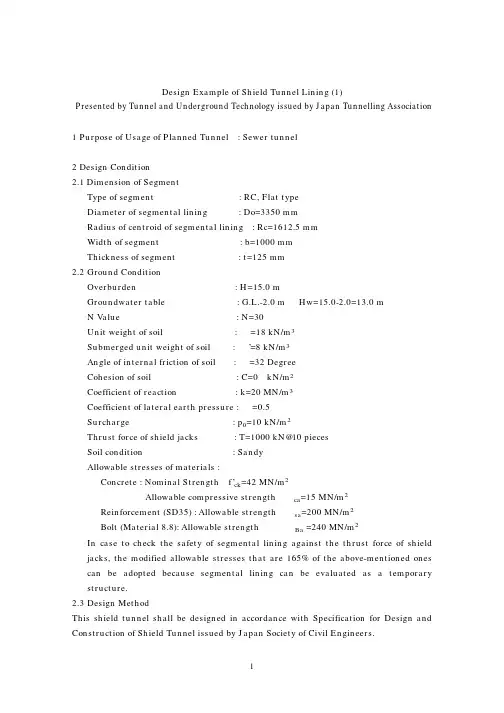
Design Example of Shield Tunnel Lining (1)Presented by Tunnel and Underground Technology issued by Japan Tunnelling Association1 Purpose of Usage of Planned Tunnel : Sewer tunnel2 Design Condition2.1 Dimension of SegmentType of segment : RC, Flat typeDiameter of segmental lining : Do=3350 mmRadius of centroid of segmental lining : Rc=1612.5 mmWidth of segment : b=1000 mmThickness of segment : t=125 mm2.2 Ground ConditionOverburden : H=15.0 mGroundwater table : G.L.-2.0 m Hw=15.0-2.0=13.0 mN Value : N=30Unit weight of soil : =18 kN/m3Submerged unit weight of soil : ƒ’=8 kN/m3Angle of internal friction of soil : =32 DegreeCohesion of soil : C=0 kN/m2Coefficient of reaction : k=20 MN/m3Coefficient of lateral earth pressure : =0.5Surcharge : p0=10 kN/m2Thrust force of shield jacks : T=1000 kN@10 piecesSoil condition : SandyAllowable stresses of materials :Concrete : Nominal Strength f’ck=42 MN/m2Allowable compressive strength ca=15 MN/m2Reinforcement (SD35) : Allowable strength ƒsa=200 MN/m2Bolt (Material 8.8): Allowable strength ƒBa =240 MN/m2In case to check the safety of segmental lining against the thrust force of shield jacks, the modified allowable stresses that are 165% of the above-mentioned ones can be adopted because segmental lining can be evaluated as a temporary structure.2.3 Design MethodThis shield tunnel shall be designed in accordance with Specification for Design and Construction of Shield Tunnel issued by Japan Society of Civil Engineers.How to compute member forces : Elastic equation method (See Table 5.2.1 in Guidelines)How to check the safety of lining : Allowable stress design method3 Load condition3.1 Computation of reduced Earth Pressure at Tunnel CrownThe vertical earth pressure at the tunnel crown (p e1) is computed by Terzahgi’s Formula.p e1=MAX(ƒ’h0,2ƒ’Do )h0=4.581 m (given by Terzahgi’s Formula(See Formula 2.2.1 in 2.2 Ground pressure of Guidelines.) < 2 Do =6.7 mp e1= 2ƒ’Do=53.60 kN/m23.2 Computation of LoadsDead load: g=ƒc@t=3.25 kN/m2 Where,ƒc=Unit weight of RC segment=26 kN/m3 :Reaction of dead load at bottom: p g=ƒg=10.21 kN/m2Vertical pressure at tunnel crownEarth pressure: p e1= 2ƒ’Do=53.60 kN/m2Water pressure: p w1=ƒwHw=130.00 kN/m2p 1= p e1+ p w1=183.60 kN/m2Vertical pressure at tunnel bottomWater pressure: p w2=ƒw(Do+Hw)=163.50 kN/m2Earth pressure: p e2= p e1+ p w1- p w2= 20.10 kN/m2Lateral pressure at tunnel crownEarth pressure: q e1=ƒ’(2Do+t/2)=27.05 kN/m2Water pressure: q w1=ƒw(Hw+t/2)=130.63 kN/m2q 1=q e1+q w1=157.68 kN/m2Lateral pressure at tunnel bottomEarth pressure: q e2=ƒ’(2Do+Do-t/2)=39.95 kN/m2Water pressure: q w2=ƒw(Hw+Do-t/2)=162.88 kN/m2q 2=q e2+q w2=202.83 kN/m2Reaction: =(2p1- q 1- q 2)/{24(EI+0.0454kRc4)}=0.00016374 mp k=kƒ=3.27 kN/m2Where,ƒ=Displacement of lining at tunnel springE=Modulus of elasticity of segment=33000000 kN/m2I=Moment of inertia of area of segment=0.00016276 m4/mk=Coefficient of reaction=20 MN/cm3Figure 3.1 shows the load condition to compute the member forces by using theelastic equation method.w2 e2p w2p e2p gFigure 3.1 Load condition4 Computation of Member ForcesTable 4.1 shows the result of computation of member forces of segmental lining.Table 4.1 Member forces of segmental lining(Deg) M (kN/m) N (kN/m) Q (kN/m)0 6.52 278.00 00.0010 5.96 279.07 -3.9320 4.39 282.02 -7.0530 2.12 286.36 -8.7740 -0.39 291.31 -8.7650 -2.65 296.05 -7.1260 -4.29 299.88 -4.3670 -5.07 302.44 -1.1880 -4.98 303.78 1.6890 -4.20 304.29 3.68100 -3.00 304.25 4.76 110 -1.61 303.88 5.00 120 -0.26 303.59 4.99 130 0.87 303.65 3.46140 1.68 304.14 2.26150 2.15 305.01 1.17160 2.37 305.99 0.43170 2.43 306.76 0.09180 2.44 307.05 0.00The maximum positive moment occurs at the tunnel crown (Section A) and the maximum negative moment occurs at the spring which is located at 70 degrees from the tunnel crown (Section B). Figure 4.1 shows the arrangement of bars in the segment.Figure 4.1 Section of segment and arrangement of bars5 Check of Safety of segmental LiningThe safety of segmental lining shall be checked at Section A , Section B and the joint part. And its safety against the thrust forces of shield jacks shall be checked.5.1 Section A and Section BFigure 5.1 shows the distribution of stress at Section A and Section B.Outside c Inside cAs’/ns’AsInside Outside c’Section A Section Bn=Ratio of moduli of elasticity between reinforcement and concrete=15Figure 5.1 Distribution of stress of critical sections of segmental liningTable 5.1 shows the computation result of the check of the safety of Section A andSection B.Table 5.1 Computation result of the check of the safety of Section A and Section BSection A B M (kNm/m) 6.52 -5.07N (kN/m) 278.000 302.44(MN/m2) (Compressive) 4.09 3.72c(MN/m2) (Compressive) - 0.26 c’(MN/m2) (Tensile) 12.02 -18.42s(MN/m2) (Compressive) 42.19 41.23s’’Both of Section A and Section B are safe.5.2 JointThe resisting moment of joint shall be not less than 60% of the one of segment body.5.2.1 Resisting Moment of Segment Body (M r)x=Depth between compressive extreme fiber and neutral axis when N=0x=-n(A s+A s’)/b+[{n(A s+A s’)/b}2+2b(A s d+A s’d’)]1/2 =3.711 cm (See Figures 4.1 and 5.1.)M rc=Resisting moment of segment body when the compressive extreme fiber stressreaches 15 MN/m2 which is the allowable compressive stress of concrete.M rs= Resisting moment of segment body when the reinforcement reaches 200 MN/m2which is the allowable stress of reinforcement.M rc=[bx(d-x/3)/2+nAs’(x-d’)(d-d’)/x]ƒca=22.24 kNm/RingM rs=[{bx(d-x/3)/2+nAs’(x-d’)(d-d’)/x}]x/{n(d-x)}ƒsa=13.87 kNm/RingM r=Min(M rc, M rs)= M rs=13.87 kNm/Ring5.2.2 Resisting Moment of Joint (M jr)x=Depth between compressive extreme fiber and neutral axis when N=0x=nA B[-1+{1+2bd/(nA B)}1/2]/b=3.011 cm (See Figure 5.2.)M jrc=Resisting moment of joint when the compressive extreme fiber stress reaches 15MN/m2 which is the allowable compressive stress of concrete.M jrB= Resisting moment of joint when the reinforcement reaches 240 MN/m2 which isthe allowable stress of bolt.M jrc=[bx(d-x/3)/2]ƒca=15.80 kNm/Ring M rs=[A B(d-x/3)’]ƒBa=10.18 kNm/RingM jr=Min(M jrc, M jrB)= M rs=10.18 kNm/Ring M jr/M r=10.18/13.87=0.733>0.6 OKA B=6.060 cm2(M22@2)Figure 5.2 Section of Joint5.3 Check of Safety against Thrust Forces of Shield Jackse=Eccentricity between center of working thrust force by one jack and centroid of segmental lining=1 cmls=Space between adjacent two jacks=10 cmA=Touching area of spreader of one jack on segmental lining=BtWhere, t=Thickness of segment=12.5 cmB=2ƒRc/Nj-ls=2ƒ 1.6125/10-0.1=0.9123 mWhere, Nj=Number of shield jacks=10 piecesA=Bt=0.1141 m2, I=Bt3/12=0.00014863 m4c=Maximum compressive stress of concrete of segment=P/A+Pe(h/2)/I=13 MN/m2 <ƒca=15• 1.65=24.75 MN/m2OKWhere, P=Thrust force of one shield jack=1000 kN(See Figure 5.3.)SegmentCentroid of mm Center of working forceof shield jackFigure 5.3 Segment and thrust force of shield jack6 ConclusionThe designed segmental lining is safe against the design loads.This design example is a design example in the Part III “References “ of Guidelines for Design of Shield Tunnel Lining issued by International Tunnelling Association. All of copyrights are reserved by International Tunnelling Association.。
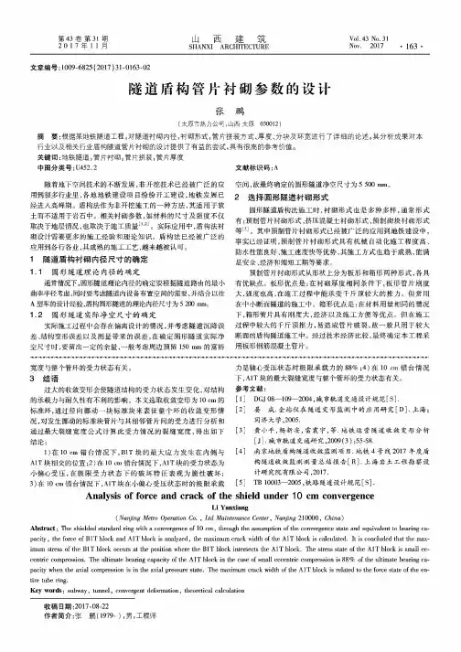
第43卷第31期 山西建筑V d.43 No.312 0 1 7 年 1 1 月SHANXI ARCHITECTURE Nov.2017 •163 •文章编号:1009-6825 (2017)31-0163-02隧道盾构管片衬砌参数的设计张鹏(太原市热力公司,山西太原030012)摘要:根据某地铁隧道工程,对隧道衬砌内径,衬砌形式,管片拼装方式、厚度、分块及环宽进行了详细的论述,其分析成果对本 行业以及相关行业盾构隧道管片衬砌的设计提供了有益的尝试,具有很高的参考价值。
关键词:地铁隧道,管片衬砌,管片拼装,管片厚度中图分类号:U452.2随着地下空间技术的不断发展,非开挖技术已经被广泛的应用到很多行业里,各地地铁建设项目纷纷开工建设,地铁发展已经进人高峰期。
盾构法作为非开挖施工的一种方法,其适用于软土而不适用于岩石中。
相关衬砌参数,如材料的尺寸及强度不仅取决于地层情况,也取决于施工质量[1’2]。
实际应用中,盾构法衬砌设计需要更多的施工经验和理论知识。
盾构法已经被广泛的应用到各行各业,其成熟的施工工艺,越来越被认可。
1隧道盾构衬砌内径尺寸的确定1.1 圆形隧道理论内径的确定通常情况下,圆形隧道理论内径的确定要根据隧道路由的最小曲率半径考虑,同时要考虑隧道内设备布置空间的需要,并结合以往 A型车的设计经验,盾构圆形隧道的理论内径尺寸为5 200 mm。
1.2 圆形隧道实际净空尺寸的确定实际施工过程中会存在偏离设计的情况,并考虑隧道沉降误 差、结构变形误差以及测量带来的误差,在确定圆形隧道实际净 空尺寸时,要留出一定的余量,一般考虑周边预留150 mm的富裕SO-S9-O-S9-O-S SO-S9-O-S SO-S9-O-S9-O-S SO-S9-O-S9-O-S SO-S9-O-S SO-S9-O-S9-O-S SO-S9-C 宽度与整个管环的受力状态有关。
3结语过大的收敛变形会使隧道结构的受力状态发生变化,对结构 的承载力与耐久性有不利的影响。
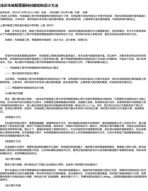
浅谈市政隧道盾构衬砌结构设计方法发布时间:2023-07-24T02:04:31.366Z 来源:《科技潮》2023年14期作者:徐爽[导读] 众所周知,市政隧道工程中的单圆盾构衬砌结构设计了单、双两层管片结构衬砌设计方案可供选用,同时总结吸纳国外盾构隧道工程案例经验。
大体来讲,城市地铁中多采用小直径盾构隧道,配合单层衬砌、公路等等大直径盾构隧道,衬砌结构相对复杂[2]。
上海市隧道工程轨道交通设计研究院上海 200235摘要:在市政工程中,隧道工程项目多采用盾构衬砌结构,该结构在隧道结构理论中占据重要地位,且种类繁多。
在本文中就简单探讨了市政隧道实际施工工程中的普通单圆隧道盾构衬砌结构设计方法,研究其中的设计参数内容,最后总结得出结果并进行讨论。
关键词:市政隧道工程;单圆盾构衬砌结构;设计方法;设计参数;结果讨论在城市化快速发展建设进程中,市政隧道工程建设规模也越来越大、技术应用内容越来越丰富。
在这其中,为解决愈发突出的空间资源矛盾,采用盾构结构来展开隧道施工工程非常有必要。
基于单圆盾构隧道的衬砌结构设计主张减小环境影响、节省地下空间、减少投资成本。
为此,有必要对市政隧道工程中的单圆盾构衬砌结构设计内容进行分析,了解结构参数内容[1]。
一、市政隧道工程中的单圆盾构衬砌结构设计要点(一)管片结构形式的设计要点众所周知,市政隧道工程中的单圆盾构衬砌结构设计了单、双两层管片结构衬砌设计方案可供选用,同时总结吸纳国外盾构隧道工程案例经验。
大体来讲,城市地铁中多采用小直径盾构隧道,配合单层衬砌、公路等等大直径盾构隧道,衬砌结构相对复杂[2]。
(二)单圆盾构衬砌结构的设计方案1计算衬砌片宽度首先,要计算衬砌片宽度,一般来说市政隧道工程中多采用钢筋混凝土管片来制作单圆盾构衬砌结构,它需要极为成熟的设计与施工经验。
在对衬砌环进行加宽加大过程中,也需要适当提高隧道纵向刚度,加速施工进度,有效降低造价成本。
如果按照国内市政隧道工程中的盾构结构展开设计,其小直径地铁区域区间中的隧道衬砌环宽度一般设计在1.2~1.5m。
盾构隧道衬砌设计指南(前言、第一章)(国际隧道协会第二工作组) 摘要:本《指南》由国际隧协第二工作组(研究组)编写,分三章:第一章介绍设计程序概要;第二章为详细的设计方法;第三章提供了一些参考资料,包括设计实例。
由于盾构隧道衬砌的设计方法不同,因此本指南并未建议应把重点放在其中某一设计方法上。
本指南提供了一些盾构隧道衬砌的基本概念,以便为隧道衬砌设计提供参考和指导。
前言 尽管本《指南》介绍了一些盾构隧道衬砌的基本概念,但它并不替代各个国家及各个工程项目的相关规范。
根据《国际隧协章程》(ITA.1976年)第二节所规定的国际隧协的目标,本指南的目的是推进盾构隧道的设计进步。
本《指南》的工作开始于1993年国际隧协第二工作组(研究组)的阿姆斯特丹会议。
经过多次研究、讨论和调查,本《指南》于1999年12月完成。
本《指南》包括三章: 第一章 概述了盾构隧道设计程序; 第二章 介绍了详细的设计方法; 第三章 提供了一些参考资料,包括盾构隧道设计实例。
由于存在各种合适的盾构隧道衬砌设计方法,因此本《指南》并未建议优先考虑某一设计方法,而是介绍了全球普遍使用的设计方法。
盾构隧道通常在软弱围岩中开挖,而非在岩石中开挖。
隧道衬砌参数,如尺寸和材料强度,不仅受围岩条件的制约,而且还受施工条件的制约。
隧道衬砌设计实践需要丰富的经验与实践及理论知识。
因此,本《指南》不可能包括隧道衬砌设计的每个方面,但本《指南》将提供一些对设计实践人员十分有用的基本知识。
希望这些基本知识随着隧道施工技术的进步会不断改进。
第一章盾构隧道衬砌设计程序概要隧道规划工作之后,总是按如下顺序设计盾构隧道衬砌。
1 坚持规范、规程和标准 拟建的隧道应按适当的规范标准、规程或标准进行设计,而这些规范标准、规程或标准由主管此项目的人员确定,或由项目负责人员与设计人员讨论确定。
2 确定隧道内部尺寸 确定拟设计隧道的内径应考虑隧道用途所需空间尺寸的大小。
盾构隧道衬砌设计指南(第三章)(国际隧道协会第二工作组) 第三章设计实例设计实例1 (本设计实例由日本隧道协会编写)1 隧道功能 设计的隧道将用作污水隧洞。
2 设计条件 2.1 管片尺寸 管片类型:RC,平板型 管片衬砌直径:DO=3350mm 管片衬砌矩心半径:RC=1612.5mm 管片宽度:b=1000mm 管片厚度:t=125mm 2.2 围岩条件 埋深:H=15.0m 地下水位:G.L.-2.0m Hw=15.0-2.0=13.0m N值:N=30 土的容重:γ=18kN/m3 土的水下容重:γ’=8kN/m3 土的内摩擦角:φ=32度 土的粘聚力:C=0 kN/m2 反作用系数:k=20MN/m3 侧向土压系数:λ=0.5 附加荷载:PO=10kN/m2 盾构千斤顶推力:T=1000kN@10个 岩土状况:砂质 材料允许应力: 混凝土: 额定强度fck=42MN/m2 允许抗压强度σca=15MN/m2 钢筋(SD35): 允许强度σsa=200MN/m2 螺栓(材料8.8): 允许强度σBa=240MN/m2 在检验管片衬砌承受盾构千斤顶推力的安全性时,可以采用修正的允许应力值(修正的允许应力值是上述应力值的165%),这是因为管片衬砌可评定为临时结构。
2.3 设计方法 本盾构隧道将依据日本土木工程师协会颁发的《盾构隧道设计与施工规范》进行设计。
l 如何检验/计算分力:弹性公式法(见本指南表Ⅱ-2)。
l如何检验衬砌的安全性:允许应力设计法。
3 荷载条件 3.1 隧道拱顶处减低土压计算 用Terzaghi公式计算隧道拱顶处的垂直土压(Pel)。
Pel=MAX(γ’h0,2γ’Do) h0=4.581m(由Terzaghi公式给出;见本《指南》2.2节“围岩压力”中的公式2.2.1)<2D0=6.7m Pel=2γ’D0=53.60kN/m2 3.2 荷载计算 静止荷载: g=γc@t=3.25kN/m2 式中: γc =RC管片的容重=26kN/m3底部静止荷载的反作用:Pg=πg=10.21kN/m2 隧道拱顶处垂直压力: 土压:Pel=2γ’Do=53.60kN/m2 水压:Pwl=γwHw=130.00kN/m2 P1= Pel+Pwl=183.60kN/m2 隧道底部垂直压力: 水压:Pw2=γw(Do+Hw) =163.50kN/m2 土压:Pe2=Pel+Pwl-Pw2 =20.10kN/m2 隧道拱顶处侧向压力: 土压:qel= λγ’(2Do+t/2) =27.05kN/m2 水压:qwl=γw (Hw+t/2) =130.63KN/m3 q1=qel+qwl=157.68kN/m2 隧道底部侧向压力: 土压:qe2= λγ’(2Do+DO-t/2) =39.95kN/m2 水压:qw2=γw(Hw+DO-t/2) =162.88kN/m2 q2=qe2+qw2=202.83kN/m2 反作用力: )]0454.0(24/[)2(4211kRc EI q q p +−−=δ =0.00016374m Pk=kδ=3.27kN/m2 式中, δ=隧道起拱线处衬砌的位移; E=管片弹性模量=33000000kN/m2; I=管片面积惯性矩; =0.00016276m4/m; k=反作用系数=20MN/cm3。
盾构隧道衬砌设计指南(第二章)(国际隧道协会第二工作组) 第二章盾构隧道衬砌设计方法1 总则 1.1 应用范围 本《指南》为i)钢筋混凝土管片衬砌和ii)在非常软弱的地层(如冲积或洪积层)中修建的盾构隧道的二次衬砌的设计提供了总要求。
本《指南》亦可用于隧道掘进机(TBM)在土层或软岩中开挖的岩石隧道的管片衬砌。
软弱围岩的物理性质如下: N≤50E=2.5×N≤125 MN/m2q u=N/80≤0.6 MN/ m2公式1.1.1式中,N:标贯试验得出的N值;E:土的弹性模量E;B-B断面A-A断面图Ⅱ-2 管片衬砌盾壳内完成的管片衬砌系统:所有管片都有盾壳内拼装、衬砌在盾壳内完成的管片衬砌系统。
扩大型管片衬砌系统:除封顶管片外,其他所有管片都在盾壳内拼装,而封顶管片在紧接盾壳之后插入,完成衬砌施作的管片衬砌系统。
厚度:隧道横截面上衬砌的厚度。
宽度:宽片的纵向长度。
接缝:衬砌中不连续的部分及管片之间的接触面。
接缝的类型: A普通型接缝 a.具有连接件a)直型钢螺栓b)曲型钢螺栓c)可重复使用的倾斜型钢螺栓d)塑料或钢制连接件b.无连接件c.具有导向杆B雌雄型接缝 C铰接型接缝 a.凸凹面铰接型接缝b.双凸面铰接型接缝c.具有中心调节元件(钢杆件)的接型接缝d.无中心调节元件的铰接型接缝D销式接缝 环形接缝:环与环之间的接缝。
径向接缝:管片之间的纵向接缝。
接缝螺栓:连接管片的钢螺栓。
在实际设计和施工中,应选取适当的衬砌构成、管片形状、接缝和防水细节、公差等,以便高效、可靠、迅速地拼装管片。
选取上述内容,应考虑下列因素: l管片拼装方法、细节及拼装设备; l隧道的功能要求,包括寿命和防水要求; l围岩和地下水状况,包括地震状况; l隧道当地的施工习惯。
1.4 符号 本《指南》中有下列符号(见图Ⅱ-3): t:厚度; A:面积; E:弹性模量; I:面积惯性矩; EI:抗挠刚度; M:力矩; N:轴向力; S:剪切力; ζ:通过接缝处毗邻管片传递的力矩的增加量与M(1+ζ)的比值。