AB软启动器使用说明-推荐下载
- 格式:pdf
- 大小:366.22 KB
- 文档页数:5
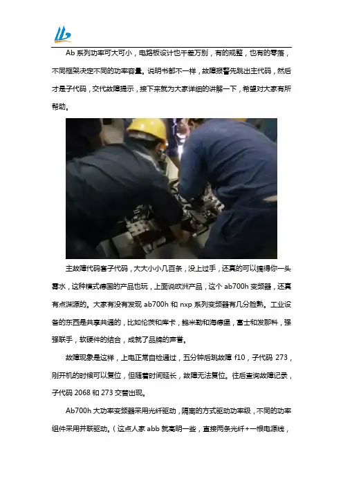
Ab系列功率可大可小,电路板设计也千差万别,有的规整,也有的零落,不同框架决定不同的功率容量。
说明书都不一样,故障报警先跳出主代码,然后才是子代码,交代故障提示,接下来就为大家详细的讲解一下,希望对大家有所帮助。
主故障代码套子代码,大大小小几百条,没上过手,还真的可以搞得你一头雾水,这种模式德国的产品也玩,上面说欧洲产品,这个ab700h变频器,还真有点渊源的。
大家有没有发现ab700h和nxp系列变频器有几分脸熟。
工业设备的东西是共享共通的,比如伦茨和库卡,鲍米勒和海德堡,富士和发那科,强强联手,软硬件的结合,成就了品牌的声誉。
故障现象是这样,上电正常自检通过,五分钟后跳故障f10,子代码273,刚开机的时候可以复位,但随着时间延长,故障无法复位。
往后查询故障记录,子代码2068和273交替出现。
Ab700h大功率变频器采用光纤驱动,隔离的方式驱动功率级,不同的功率组件采用并联驱动。
(这点人家abb就高明一些,直接两条光纤+一根电源线,即简化了电路,性能还出奇的稳定)。
所以严格的说,ab700h变频器只是驱动采用了光纤驱动,而驱动组模上必要的检测电路还是通过模拟接口完成的。
作为维修人员,这点很重要,这是判断故障点的分水岭!上半部分硬件有:小信号处理板,控制板,I/o板。
通讯,板卡,eeprom等故障由上半部分完成。
下半部分硬件包括驱动板,功率单元。
电流检测、母线检测、相位检测、温度检测、驱动电源检测都在下半部分完成。
杭州联凯机电工程有限公司成立于2011年,是一家专业从事工业自动化设备销售、维护及电气系统维修改造的高科技公司。
主要经营西门子(SIEMENS)ABB、施耐德(Schneider)等品牌的变频器、直流调速器、软启动器、PLC、触摸屏、数控系统、单片机、电路板等各种进口工业仪器设备,服务中心配备了百万备品备件以及完备的诊断检测仪器和软件诊断技术,拥有一支技术精湛、经验丰富的技术团队。

AB变频器使用说明书
AB变频器调试说明书
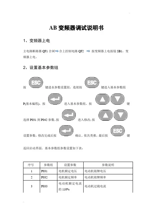
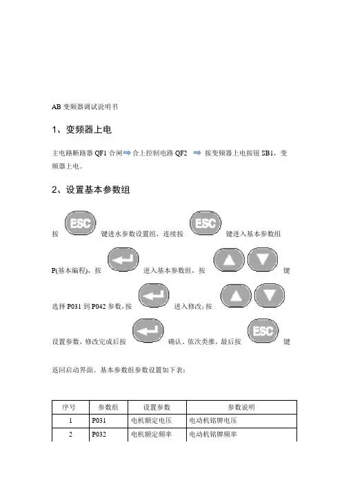
1、变频器上电
主电路断路器QF1合闸合上控制电路QF2 按变频器上电按钮SB1,变频器上电。
2、设置基本参数组
按键进水参数设置组,连续按键进入基本参数组P(基本编程),按进入基本参数组,按键选择P031到P042参数,按进入修改;按设置参数,修改完成后按确认。
依次类推,最后按键返回启动界面。
基本参数组参数设置如下表:
序号参数组设置参数参数说明
1P031电机额定电压电动机铭牌电压
2P032电机额定频率电动机铭牌频率
电动机额定电流
3P033
电动机过载电流
的110%
3、设置端子块组参数
按照设置基本参数组参数的步骤,设置下列参数:
4、启动变频器
a
、当变频器控制柜“本地/远程”旋钮打到“本地”时,变频器通过柜门的“启
动”、“停止”按钮启动和停止变频器。
变频器通过面板
改变变频器的给定频率。
b、当变频器控制柜“本地/远程”旋钮打到“远程”时,变频器通过柜门的“启动”、“停止”按钮启动和停止变频器。
变频器通过触摸屏和上位机给定频率。
说明:本说明书中的参数设置是根据本公司设计的控制电路设置的,如果电路发生更改需要重新设置参数。

A B软启动操作使用说明 Revised by Petrel at 2021A-B软启动器操作使用说明电化厂机动科二00一年十月一.软启动器的起动方式选择┅┅┅┅┅ 2 二.软启动器的参数查看方法┅┅┅┅┅ 3 三.参数修改┅┅┅┅┅ 5四.常见故障信息及消除方法┅┅┅┅┅ 5 五.常见故障说明┅┅┅┅┅ 7 六.常用参数及说明┅┅┅┅┅ 8 七.软启动器的初次调试┅┅┅┅┅11软启动器使用操作说明一.软启动器的起动方式选择:软启动器的起动方式常用的有以下几种:1.软起动:该方式是最常用的起动方式,电动机可根据参数设定的初始转矩进行起动。
起动加速时间在0—30S之间,由用户自行调节。
起动斜坡加速期间,输出至电机的电压不断上升,当软启动器的控制器检测到电动机已达到额定转速状态,则输出电压将自动切换到全电压。
(若设定的起动时间为30S,在20S的时候如果电动机已达到额定转速,电机端电压已达到全电压,则不必等到30S)2.限流起动:限流起动顾名思义,限制电机的起动电流,该方式为电动机提供一固定电压的降压起动。
限流水平可由用户在电机满载电流的500-600%间调节,限流起动时间0—20S由用户设定。
在起动过程中,当软起动器的控制器检测到电机的额定转速时,输出电压将自动切换成全压输出,这点与软起动方式有些区别:软起动过程电压是无级不断增加的;而限流起动是始终以一固定电压起动的。
3.全压起动:该方式同一般设备的启动相同,一般来说,既然选用了软启动器就不太会选用该方式进行起动。
4.可选择的突跳起动:该起动功能一般是附加于软起动方式或限流起动方式之中,为电动机起动提供一个大提升转矩以克服负载惯性,突跳时间可由用户在—之间设定。
我厂采用的软起动方式主要有以下两种:1.限流加突跳起动方式:该方式主要用于PVC的水环压缩机、抽风机、鼓风机和排渣泵等设备,因为这些设备的电机容量较大,起动电流较大,其供电线路也较长,采用限流起动,可减少对配电室母线电压的影响,以免造成当大设备启动时,母线压降大,使照明及其他设备失电跳闸的情况发生。
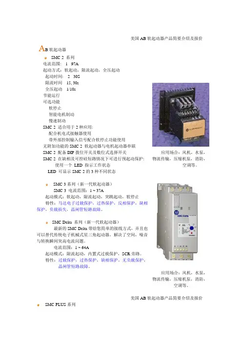
美国AB软起动器产品简要介绍及报价A B软起动器SMC-2 系列电流范围: 1 - 97A起动方式:软起动,限流起动,全压起动起动时间: 2 - 30S限流时间15, 30s全压起动1/10s节能运行可选功能- 软停止- 智能电机制动- 慢速制动SMC-2 适合用于2种应用:- 配合机电式接触器使用- 带外部控制输入信号配合软停止功能使用无附加功能的SMC-2 软起动器与电机起动器串联SMC-2 配备DIP拨位开关及数位式选择开关SMC-2 在缺相及可控硅短路情况下可进行预起动保护: - 使用一个LED 指示工作状态- LED 可显示SMC-2的3种不同状态应用场合:风机,水泵,物流传输,压缩机泵,消防,空调等。
SMC-3系列(新一代软起动器)SMC-3 电流范围:1 ~ 37A起动模式:软起动,限流起动,突跳起动,软停止特性:马达电子过载保护,过热保护,反相保护,缺相保护,负载损失,晶闸管短路故障。
SMC-Delta 系列(新一代软起动器)最新的SMC-Delta带给您简单的接线方式,并且也可以替代传统电子机械式星三角起动器。
解决了空间,噪音与转换瞬间突高电流问题。
电流范围:1 ~ 64A起动模式:限流起动,内置式过载保护,SCR旁路。
特性:过载保护,过热保护,缺相保护,无负载保护,晶闸管短路故障。
应用场合:风机,水泵,物流传输,压缩机泵,消防,空调等。
美国AB软起动器产品简要介绍及报价SMC-PLUS系列在标准软起动产品中具有最佳性能电流范围:1 ~ 1000A电压范围:200…600V AC,50/60Hz起动方式:软起动(带突跳起动)限流起动全压起动特性:LED故障指示灯电子式调节节能可调节辅助触头特殊功能选择:(选型时只能选一种)1.软停止2. 泵控3. 智能电机制动4.预置低速控制5. 低速制动6. 准确停车。
应用范围:纺织、冶金、水处理、食品和保健品加工、采矿和机械装备等行业SMC Dialog plus系列在标准软起动产品中具有最佳性能电流范围:1… 1,000 A电压范围:200…600V AC,50/60Hz起动方式:软起动(带突跳起动)限流起动双斜坡起动全压起动特性:电子式过载保护电网监视SCANPort通讯功能液晶显示现场编程可调节辅助触头特殊功能选择:(选型时只能选一种)1.软停止2. 泵控3. 智能电机制动4. 预置低速控制 5. 低速制动 6. 准确停车。
AB变频器调试说明书1、变频器上电主电路断路器QF1合上控制电路QF2 按变频器上电按钮SB1,变频器上电。
2、设置基本参数组按键进水参数设置组,连续按键进入基本参数组P(基本编程),按进入基本参数组,按键选择P031到P042参数,按进入修改;按设置参数,修改完成后按确认。
依次类推,最后按键返回启动界面。
基本参数组参数设置如下表:序号参数组设置参数参数说明1 P031 电机额定电压电动机铭牌电压2 P032 电机额定频率电动机铭牌频率3 P033 电动机额定电流的110%电动机过载电流3、设置端子块组参数按照设置基本参数组参数的步骤,设置下列参数: 1 T051 15(模拟量输入2控制) 数字量输入1选择 2 T055 2(电动机运行) 继电器输出1选择 3 T060 0(准备好/故障) 继电器输出1选择4T0731(4-20mA) 模拟量输入2选择,将DIP 开关拨到AI1 20mA 5 T08214(4-20mA 输出频率)模拟量输出1选择6 T085 14(4-20mA 输出电流)模拟量输出1选择4、启动变频器a 、当变频器控制柜“本地/远程”旋钮打到“本地”时,变频器通过柜门的“启动”、“停止”按钮启动和停止变频器。
变频器通过面板4 P034 0 最小频率5 P035 50 最大频率6 P036 2(2线制) 起动源7 P038 0(变频器键盘) 速度基准值 8 P039 60s 加速时间 9 P040 60s 减速时间 10P0423(自动/手动)自动模式改变变频器的给定频率。
b、当变频器控制柜“本地/远程”旋钮打到“远程”时,变频器通过柜门的“启动”、“停止”按钮启动和停止变频器。
变频器通过触摸屏和上位机给定频率。
说明:本说明书中的参数设置是根据本公司设计的控制电路设置的,如果电路发生更改需要重新设置参数。
DGQ-C系列软起动装置使用说明书- 1-●警示事项:●感谢您选用大禹电气科技股份有限公司的智能化电机软起动器产品,我们将以优异的产品性能回报您的信任和厚爱!●本软起动器产品在安装、使用、维护过程中必须注意以下事项:安装前请务必详细阅读本说明书。
必须由专业技术人员安装本软起动器。
严禁本软起动器输出部(U.V.W)接补偿电容器。
不得用兆欧表测量软起动器输入输出之间的绝缘电阻,否则可能因过压而损坏起动器内元器件。
软起动器或相关的其它设备应可靠接地。
设备维修时必须切断输入电源。
非专业人士不要自行拆卸、改装、维修本产品。
DGQ-C系列软起动装置使用说明书- 2-1 序1.1概述DGQ-C 系列智能软起动控制装置是专门为各种行业中不同功率的低压异步电动机的起停而设计的。
该装置控制系统以DSP 为控制核心,采用最先进的电机控制算法理论及电力电子技术,实现了装置全数字化自动控制,使它具有很强的抗干扰能力,不会产生无故障停机现象。
为了增加装置的适用性、方便性,系统设计了交流接触器旁路运行输出及无交流接触器本机运行方式可供选择,在起动方式上它具有电压斜坡起动、限流起动等多种方式,而停机方式有自由停机、软停机、刹车制动可供选择,可适应各种载荷电机的控制需要。
DGQ-C 系列智能软起动控制装置可以针对不同的载荷类型设定不同的起动及停止参数,以最佳的起动效果来起动电机。
通常情况下将电机的起动电流控制在额定电流的三倍左右。
并且该装置还具有断相、堵转、电流不平衡、过压、欠压、短路、过热保护等完善的保护功能。
不仅有效地保护了电机,延长了负载系统与电机的使用寿命,而且还能消除电机起动时对厂用电网的冲击。
1.2系统原理DGQ-C 系列智能软起动控制装置系统原理框图(见图一)。
(图一)DGQ-C系列软起动装置使用说明书- 3-1.3主要特点◆控制系统采用人性化的设计,具有友好的中文显示人机界面和多种组合控制操作模式,显示清晰,操作简单,极大的方便了用户的使用;◆采用哈佛总线及整体化设计,减少系统连线,DSP 芯片生产工艺采用SMT 贴片技术,整机出厂前进行了高温老化及振动实验,保证了可靠的产品质量;◆具有多种起动方式,电压斜坡式起动方式可得到最佳的输出转矩;恒流起动方式可限制最大起动电流,但起动时间稍长。
AB变频器调试说明书
1、变频器上电
主电路断路器QF1合上控制电路QF2 按变频器上电按钮SB1,变频器上电。
2、设置基本参数组
按键进水参数设置组,连续按键进入基本参数组
P(基本编程),按进入基本参数组,按键选择P031到P042参数,按进入修改;按
设置参数,修改完成后按确认。
依次类推,最后按键返回启动界面。
基本参数组参数设置如下表:
序号参数组设置参数参数说明
1 P031 电机额定电压电动机铭牌电压
2 P032 电机额定频率电动机铭牌频率
3、设置端子块组参数
按照设置基本参数组参数的步骤,设置下列参数:
4、启动变频器
a、当变频器控制柜“本地/远程”旋钮打到“本地”时,变频器通过柜门的“启
动”、“停止”按钮启动和停止变频器。
变频器通过面板
改变变频器的给定频率。
b、当变频器控制柜“本地/远程”旋钮打到“远程”时,变频器通过柜门的“启动”、“停止”按钮启动和停止变频器。
变频器通过触摸屏和上位机给定频率。
说明:本说明书中的参数设置是根据本公司设计的控制电路设置的,如果电路发生更改需要重新设置参数。

A-B软启动器操作使用说明一.软启动器的起动方式选择┅┅┅┅┅ 2 二.软启动器的参数查看方法┅┅┅┅┅ 3 三.参数修改┅┅┅┅┅ 5 四.常见故障信息及消除方法┅┅┅┅┅ 5 五.常见故障说明┅┅┅┅┅7 六.常用参数及说明┅┅┅┅┅8 七.软启动器的初次调试┅┅┅┅┅11软启动器使用操作说明一.软启动器的起动方式选择:软启动器的起动方式常用的有以下几种:1.软起动:该方式是最常用的起动方式,电动机可根据参数设定的初始转矩进行起动。
起动加速时间在0—30S之间,由用户自行调节。
起动斜坡加速期间,输出至电机的电压不断上升,当软启动器的控制器检测到电动机已达到额定转速状态,则输出电压将自动切换到全电压。
(若设定的起动时间为30S,在20S的时候如果电动机已达到额定转速,电机端电压已达到全电压,则不必等到30S)2.限流起动:限流起动顾名思义,限制电机的起动电流,该方式为电动机提供一固定电压的降压起动。
限流水平可由用户在电机满载电流的500-600%间调节,限流起动时间0—20S由用户设定。
在起动过程中,当软起动器的控制器检测到电机的额定转速时,输出电压将自动切换成全压输出,这点与软起动方式有些区别:软起动过程电压是无级不断增加的;而限流起动是始终以一固定电压起动的。
3.全压起动:该方式同一般设备的启动相同,一般来说,既然选用了软启动器就不太会选用该方式进行起动。
4.可选择的突跳起动:该起动功能一般是附加于软起动方式或限流起动方式之中,为电动机起动提供一个大提升转矩以克服负载惯性,突跳时间可由用户在0.0—2.0S之间设定。
我厂采用的软起动方式主要有以下两种:1.限流加突跳起动方式:该方式主要用于PVC的水环压缩机、抽风机、鼓风机和排渣泵等设备,因为这些设备的电机容量较大,起动电流较大,其供电线路也较长,采用限流起动,可减少对配电室母线电压的影响,以免造成当大设备启动时,母线压降大,使照明及其他设备失电跳闸的情况发生。
Allen-Bradley Bulletin 150SMC Dialog Plus™Controller—Getting StartedIntroduction This guide provides you with the basic information required to startup your SMC Dialog Plus controller. Factory default settings andinformation regarding installing, programming, and calibrating thecontroller are described here. For detailed information on specificproduct features or configurations, refer to the SMC Dialog Plus UserManual, Publication 150-5.3.This guide is intended for qualified service personnel responsible forsetting up and servicing these devices. You must have previousexperience with and a basic understanding of electrical terminology,configuration procedures, required equipment, and safety precautions.SMC Dialog Plus is a trademark of Rockwell Automation.2Installation The open-style design of the SMC Dialog Plus controller requires thatit be installed in an enclosure. The internal temperature of theenclosure must be kept within 0…5°C (32…122°F).The controller is convection cooled. It is important to mount thecontroller in a position that allows air to flow vertically through thepower structure. Allow for a minimum of six inches (15 cm) of freespace around all sides of the controller.Wiring Power WiringRefer to the product nameplate for power lug termination informationincluding:•Lug wire capacity•Tightening torque requirements•Lug kit catalog numbers (97…1000A)Control WiringRefer to the product nameplate for control terminal wire capacity andtightening torque requirements. Each control terminal will accept amaximum of two wires.The SMC Dialog Plus controller accepts control power input of either100…240VAC, (+10/–15%) single-phase, 50/60Hz or 24V AC/DC.Refer to the product nameplate prior to applying control power.Connect control power to the controller at terminals 11 and 12. Thecontrol power requirement for the control module is 40 V A. Forcontrollers rated 97…1000A, control power is also required for theheatsink fans as defined in Table A. Depending on the specificapplication, additional control circuit transformer V A capacity may berequired.Table AHeatsink Fan Power Requirements3Control TerminalsFigure 1SMC Dialog Plus Controller Control TerminalsTable BControl Terminal DesignationDo not connect any additional loads to these terminals. These “parasitic” loads may cause problems with operation, which may result in false starting and stopping.4Figure 2Typical Wiring DiagramFigure 3Heatsink Fan WiringRefer to Chapter 3 of the SMC Dialog Plus Controller User Manual (Publication 150-5.3) for optional 220/240V AC fan power connections and other sample wiring diagrams. Chapter 7 of Publication 150-5.3 also provides typical wiring diagrams for the control options (for example, Pump Control).❶Customer supplied.5 Programming The SMC Dialog Plus controller can be programmed with the built-inkeypad and LCD display or with the optional Bulletin 1201 humaninterface modules. Parameters are organized in a four-level menustructure and divided into programming groups.Keypad Description。
A-B软启动器操作使用说明电化厂机动科二00一年十月一.软启动器的起动方式选择┅┅┅┅┅2二.软启动器的参数查看方法┅┅┅┅┅3三.参数修改┅┅┅┅┅5四.常见故障信息及消除方法┅┅┅┅┅5五.常见故障说明┅┅┅┅┅7六.常用参数及说明┅┅┅┅┅8七.软启动器的初次调试┅┅┅┅┅11软启动器使用操作说明一.软启动器的起动方式选择:软启动器的起动方式常用的有以下几种:1.软起动:该方式是最常用的起动方式,电动机可根据参数设定的初始转矩进行起动。
起动加速时间在0—30S之间,由用户自行调节。
起动斜坡加速期间,输出至电机的电压不断上升,当软启动器的控制器检测到电动机已达到额定转速状态,则输出电压将自动切换到全电压。
(若设定的起动时间为30S,在20S的时候如果电动机已达到额定转速,电机端电压已达到全电压,则不必等到30S)2.限流起动:限流起动顾名思义,限制电机的起动电流,该方式为电动机提供一固定电压的降压起动。
限流水平可由用户在电机满载电流的500-600%间调节,限流起动时间0—20S由用户设定。
在起动过程中,当软起动器的控制器检测到电机的额定转速时,输出电压将自动切换成全压输出,这点与软起动方式有些区别:软起动过程电压是无级不断增加的;而限流起动是始终以一固定电压起动的。
3.全压起动:该方式同一般设备的启动相同,一般来说,既然选用了软启动器就不太会选用该方式进行起动。
4.可选择的突跳起动:该起动功能一般是附加于软起动方式或限流起动方式之中,为电动机起动提供一个大提升转矩以克服负载惯性,突跳时间可由用户在0.0—2.0S之间设定。
我厂采用的软起动方式主要有以下两种:1.限流加突跳起动方式:该方式主要用于PVC的水环压缩机、抽风机、鼓风机和排渣泵等设备,因为这些设备的电机容量较大,起动电流较大,其供电线路也较长,采用限流起动,可减少对配电室母线电压的影响,以免造成当大设备启动时,母线压降大,使照明及其他设备失电跳闸的情况发生。
Instruction Leaflet for the S701X25N3BPSoft Start Controller with Auxiliary Contact DescriptionThe S701 device is a reduced voltage soft start controllerdesigned to control acceleration and deceleration of three-phase motors. With the Auxiliary Contact Option, it is possibleto control an external bypass to reduce heating and lengthenacceleration and deceleration times.The S701 provides the user with the ability to adjust initialtorque, ramp up and down time, and also select kick start forhigh inertia loads.InstallationWARNINGDO NOT INSTALL OR PERFORM MAINTENANCE ON THIS DEVICE WHILE EQUIPMENT IS ENERGIZED. DEATH OR SEVERE PERSONAL INJURY CAN RESULT FROM CON-TACT WITH ENERGIZED EQUIPMENT. VERIFY THAT NO VOLTAGE IS PRESENT BEFORE PROCEEDING WITH INSTALLATION OR MAINTENANCE.Only qualified persons, as defined in the National Electric Code, who are familiar with the installation, maintenance and operation of this device and the equipment onto which it is to be installed, as well as applicable local, state and national reg-ulations and industry standards and accepted practices regarding safety of personnel and the equipment safety should be permitted to install, maintain or operate this device. These instructions are provided only as a general guide to such quali-fied persons and are not all-inclusive. They do not cover every application or circumstance which may arise in the installation, maintenance or operation of this equipment. Users are advised to comply with all local, state and national regulations and industry standards and accepted practices regarding safety of personnel and equipment.CAUTIONREMOVE ALL POWER FROM THE INSTALLATION BEFORE ATTEMPTING TO INSTALL OR REMOVE THIS DEVICE. THIS INCLUDES L1, L2, L3 AS WELL AS A1, A2, 11, 12, 13 and 14.Mounting Guidelines for S701X25N3BP Important — The controller is designed for vertical mounting in free air. If the controller is mounted horizontally, the load cur-rent must be reduced to 50% of rated current. MaintenanceCooling fins must be kept clean and free from dust. The airflow must not be blocked.Figure 1. Recommended Mounting DistanceFigure 2. DimensionsWiring Directions!IMPORTANTWhen using electrical or pnuematic tools for screw termi-nals, observe maximum torque limits.75°C AWG (mm2)AWG(mm2)18 - 10 (1.5 -6)20 - 16 (0.5 - 1.5)16 - 10(2 x 1.5-6)2 x 20 - 18(2 x 0.5 - 0.75)16 - 10 (1.5 - 6)20 - 16 (0.5 - 1.5)2 x 16 - 10(2 x 1.5 - 6)2 x 20 - 16(2 x 0.5 - 1.5)18 - 8 (1 - 10)20 - 16 (0.5 - 1.5)2 x 18 - 10(2 x 1 - 6)2 x 20 - 16(2 x 0.5 - 1.5)Posidrive 11.2 Nm max.[4.4 lb-in max.]N/A6 mm1.2 Nm max.[4.4 lb-in max.]3 mm0.4 Nm max.[3.5 lb-in max.]* UL T ested.***Effective 01/021Effective 01/022Wiring DiagramsFigure 3. Wiring DiagramsUsing Line Voltage to Control S701When the contactor C1 is switched to the ON state, the motor controller will soft start the motor according to the set-tings of the ramp-up time and initial torque adjustments.When the contactor C1 isswitched to the OFF state, the motor will be switched off instantaneously.In this application, thecontactor will have no load during making operation.The contactor will carry and break the nominal motor cur-rent. Maximum voltage in this application is 300V AC.Separate Input Signal to S701When the control input is switched to the ON state (S closed), the motor control-ler will soft start the motor according to the settings of the ramp-up time and initial torque adjustments.When the control input is switched to the OFF state (S open), the motor will be switched off instantaneously only if the ramp-down time is adjusted to 0.With any other setting, the motor will be soft stopped according to the settings of the ramp-down time adjustment.Soft Reversing of Motors up to 5 hp/4 kWA soft reversing of a motor can easily be achieved by con-necting a reversing relay to the soft start controller.The reversing relay type S511 will determine the direction of rotation forward or reverse and the soft start type S701 will perform soft-starting and soft-stopping of the motor.If soft stop is not required, the application can be simplified by connecting the control cir-cuit of the soft start controllerto the main terminals asshown in Figure 6. A delay ofapproximately 0.5 secondsbetween forward and reversecontrol signal must be allowed to avoid influence from the volt-age generated by the motor during turnoff.Reversing of Motors Up to 15 hp/11 kWA soft-reversing of motors can easily be achieved when the motor load exceeds 5 hp/4 kW by connecting a mechanical reversing contactor to the soft start controller.The reversing contactor will determine the direction of rota-tion forward or reverse and the soft start controller type S701 will perform soft-starting and soft-stopping of the motor.If the contactors are always switched in no load conditions, the lifetime of the contactors will normally exceed 10 million cycles.Overload Protection with Manual Motor StarterOverload protection of the motor is easily achieved by installing a manual motor starter on the supply side of the motor.The manual motor starter pro-vides means for padlocking and the necessary clearance for use as a circuit isolator according to EN60204-1.Adjust the current limiter on the manual motor starteraccording to the rated nominal current of the motor.L1L2L3C1NOTE: Use thermal overload protection as required by the National Electric Code (NEC).AC-53b Application — with Bypass and START/STOPAC-53a Application — No Bypass and START/STOPS70124-300VL1 L2 L3T1 T2 T3A1 A2L1L2L3MC1Figure 4. Line Controlled Soft Start *S701Control Voltage 24 - 300 VL1 L2 L3T1 T2 T3A1 A2L1L2L3MSC1Figure 5. Input Controlled Soft Start *S511L1L2L3C1S701Figure 6. CombiningReversing ElectronicContactor and Soft StartController *L1L2L3FWDREVS701Figure 7. Combining Reversing Mechanical Contactor and Soft Start Controller *Figure 8. OverloadProtection with Manual Motor Starter** Use UL specified backup fuse.Effective 01/023Overload Protection with Mechanical StarterOverload protection of the motor is easily achieved by installing a mechanical starter on the supply side of the soft start controller.The overload provides the necessary motor protection for an overload condition.A short circuit protectivedevice is required to meet UL requirements.* Use UL specified backupfuse.SpecificationsTable 1. Thermal SpecificationsTable 2. Insulation SpecificationsCurrent DeratingCurrent Derating in High Temperature ApplicationsOperation in ambient temperatures exceeding 40°C is possible if the power dissipation is limited either by reducing the steady-state current or by reducing the duty cycle of the soft starter as shown in Table 3.Table 3. Temperature SpecificationsTable 4. Current Derating by Trip ClassEMCThis compartment meets the requirements of the product stan-dard EN60947-4-2 and is CE marked according to this standard.Table 5. Output Specifications — Main CircuitTable 6. Control SpecificationsProduct SelectionTable 7. Product Description and Item SelectionShort Circuit ProtectionTwo types of short circuit protection can be used:short circuit protection by circuit breaker short circuit protection by fusesShort circuit protection is divided into two levels — Type 1 and Type 2.Type 1 — protects the installationType 2 — protects the installation and the semiconductors inside the motor controllerShort Circuit Protection by Circuit BreakerA 3-phase motor with a correctly installed and adjusted over-load relay will not short-circuit totally to earth or between the 3 phases. Part of the winding will normally limit the short circuit current to a value that will cause instantaneous magnetic trip-ping of the circuit breaker without damage to the soft starter. The magnetic trip response current is approximately 11 times the maximum adjustable current.DescriptionSpecification Power dissipation for continuous operation PD max.2 W/APower dissipation for intermittent operation PD 2 W/A x duty cycle Cooling Method Natural convection Mounting (No Derating)Vertical ±30° Operating temperature range, EN60947-4-2 (no derating)-5° to 40°C* [23° to 104°F]* UL Tested.Storage temperature, EN60947-4-2-20° to 80°C [-4° to 176°F]Max. operating temperature with current derating according to table60°C [140°F]DescriptionSpecification Rated insulation voltage Ui 660 Volt Rated impulse withstand voltage Uimp 4 kVolt Installation categoryIIIAmbient Temperature S701X25N3BP 50°C [122°F]20A continuous Limited Duty Cycle Rating by 50°C On-time max. 15 min. Duty cycle max. 0.860°C [140°F]17A continuous Limited Duty Cycle Rating by 60°COn-time max. 15 min. Duty cycle max. 0.65Figure 9. Overload Protection with Mechanical Starter *Overload Trip ClassWithout BypassWith Bypass10A 10203025A 25A 20A 15A30A 30A 24A 19.5AApprovals: UL Std. No. 508Environment: Degree of Protection / Pollution Degree: IP20 / 3DescriptionSpecificationShort circuit protecting fuse (max.)80 A g L/g G. No time delay Operational current (max.)25A AC-53a, 30A AC-53b Semiconductor protecting fuse (max.)6300 A 2S Overload relay trip class10 or 10ADescriptionSpecificationControl voltage range24 – 300V AC/DC Control current/power (max.)15 mA/2 VARamp-Up time Adjustable from 0.5 to 20 sec.Ramp-Down time Adjustable from 0.5 to 20 sec.Initial torqueAdjustable from 0 to 85% of nominal torque with optional Kick StartOutput/Current voltage (max.)0.5A AC14, AC15,24 – 480V AC 50 – 60 HzFuse (max.)10 A g L/g G. l 2t max. 72 A 2SLine Voltage (V AC)Motor Size w/o Bypass Motor w/Bypass Control Voltage Range** 24 – 480V for CE only.Controller TypeDesignationhp / kW hp / kW AC/DC208 – 23010 / 7.510 / 7.524 – 300V S701C25N3BP 400 – 48015 / 1120 / 1524 – 300V S701E25N3BP 550 – 60020 / 1525 / 1824 – 300V S701G25N3BP© 2002 Eaton Corporation All Rights Reserved Printed in USA Effective 01/02Short Circuit Protection by FusesType 1S701X25N3BP — protection max. 80A g I/g L/g G 63A T Type 2S701X25N3BP — protection max. I 2t of the fuse 6300A 2S NOTE:S701X25N3BP — When protected by H class fuses,this device is rated for use on a circuit capable of delivering not more than 5000 rms symmetrical amperes, 600V maximum.How to Adjust Time and Torque, Figure 10The Soft Starter will read time and torque settings in the OFF state. Repeated starts may trip the motor protection relay. DO NOT set the rotary switches in between positions. This cor-rupts the time and torque adjustment. Use screwdriver 2 mm x 0.5 mm.Ramp-Up Time and Initial TorqueTable 8. Ramp-Up Time and Initial Torque (Standard Load)Kick Start/Break LooseIf it is not possible to reach a time sufficient for the application, it may be necessary to kick start the load.Table 9. Kick Start/Break Loose (High Inertia Loads)Ramp-Down TimeFollow Table 8 to set Ramp-Up and Initial Torque .Table 10. Ramp-Down Time, e.g. Pump LoadsFigure 10. Time and Torque AdjustmentPositionSetting/AdjustmentSet the Ramp-Up switch to maximum.Set the Ramp-Down switch to minimum.Set the Initial Torque switch to minimum.Apply control signal for a few seconds. If the load does not rotate immediately, increment the Initial Torque and try again. Repeat until the load starts to rotate immediately on startup.Adjust Ramp-Up time to the estimated start time (the scale is in seconds) and start the motor.Decrease the Ramp-Up time until mechanical surge is observed during start.Increase the time one step to eliminate the surge.PositionSetting/AdjustmentSet the Ramp-Up switch to maximum.Set the Ramp-Down switch to minimum.Set the Initial Torque switch to minimum kick start torque.Apply control signal for a few seconds. If the load stops right after the 200ms “kick ”, increment the Initial Torque and try again. Repeat until the load continues to rotate after the “kick ”.Adjust Ramp-Up time to the desired start time (the scale is in seconds) and start the motor.PositionSetting/AdjustmentSet the Ramp-Down switch to maximum.Switch off the control voltage and observe any mechanical surges on the load. If there are none, decrement Ramp-Down switch and try again. Repeat until mechanical surge on the load is observed.Increase the time one step to eliminate the surge.。
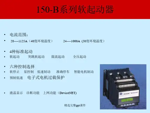
美国AB软起动器产品简要介绍及报价A B 软起动器
SMC-2 系列
电流范围: 1 - 97A
起动方式:软起动,限流起动,全压起动
起动时间: 2 - 30S
限流时间15, 30s
全压起动1/10s
节能运行
可选功能
- 软停止
- 智能电机制动
- 慢速制动
SMC-2 适合用于2种应用:
- 配合机电式接触器使用
- 带外部控制输入信号配合软停止功能使用
无附加功能的SMC-2 软起动器与电机起动器串联SMC-2 配备DIP拨位开关及数位式选择开关
SMC-2 在缺相及可控硅短路情况下可进行预起动保护: - 使用一个LED 指示工作状态
- LED 可显示SMC-2的3种不同状态
应用场合:风机,水泵,物流传输,压缩机泵,消防,
空调等。
SMC-3系列(新一代软起动器)
SMC-3 电流范围:1 ~ 37A
起动模式:软起动,限流起动,突跳起动,软停止
特性:马达电子过载保护,过热保护,反相保护,缺
相保护,负载损失,晶闸管短路故障。
SMC-Delta 系列(新一代软起动器)
最新的SMC-Delta带给您简单的接线方式,并且
也可以替代传统电子机械式星三角起动器。
解决了空间,噪
音与转换瞬间突高电流问题。
电流范围:1 ~ 64A
起动模式:限流起动,内置式过载保护,SCR旁路。
特性:过载保护,过热保护,缺相保护,无负载保护,
晶闸管短路故障。
应用场合:风机,水泵,
物流传输,压缩机泵,消防,
空调等。
美国AB软起动器产品简要介绍及报价SMC-PLUS系列
在标准软起动产品中具有最佳性能
电流范围:1 ~ 1000A
电压范围:200…600V AC,50/60Hz
起动方式:
软起动(带突跳起动)
限流起动
全压起动
特性:
LED故障指示灯电子式调节
节能可调节辅助触头
特殊功能选择:(选型时只能选一种)
1.软停止
2. 泵控
3. 智能电机制动
4.预置低速控制
5. 低速制动
6. 准确
停车。
应用范围:纺织、冶金、水处理、食品和保
健品加工、采矿和机械装备等行业
SMC Dialog plus系列
在标准软起动产品中具有最佳性能
电流范围:1… 1,000 A
电压范围:200…600V AC,50/60Hz
起动方式:
软起动(带突跳起动)
限流起动
双斜坡起动
全压起动
特性:电子式过载保护电网监视
SCANPort通讯功能液晶显示
现场编程可调节辅助触头
特殊功能选择:(选型时只能选一种)
1.软停止
2. 泵控
3. 智能电机
制动4. 预置低速控制 5. 低速
制动 6. 准确停车。
应用范围:纺织、冶金、水处理、食品
和保健品加工、采矿和机械装备
等行业
AB软起动的应用范围AB智能马达控制器广泛应用于纺织、冶金、水处理、食品和保健品加工、采矿和机械装备等行业。
典型应用简介如下:
1. 空气压缩机- 大容量电动机轻载时进入节能运行状态;当输入电源电压不平衡时,可以自动调节使相电流平衡,减少电动机发热和延长寿命。
2. 铸件清理滚筒- 正常运行和维修时,负载变化很大,分别利用双斜坡起动,减少机械冲击。
利用智能电动机制动或准确停车控制,提高装卸工件效率。
3. 离心泵- 利用泵控制功能,减少启动和停止时液流冲击所产生地系统喘振现象,节省系统维修费用。
4. 带锯- 利用软启动和SMB(智能电机制动)制动,克服大惯量起动和实现准确定位。
5. 桥式起重机- 利用双斜坡起动,实现加速过程最有效控制,提高生产率并减少产品的损坏。
6. 皮带运输机和自动传输线- 利用软启动和预置低速运行,实现平滑起动,避免产品移位和液体溢出。
7. 通风机- 利用软启动取代旧的机电启动器,减少皮带磨损和机械冲击,节省维修费用。
8.码垛机械- 利用双斜坡起动和预置低速运行,适应不同的包装要求,避免冲击所导致的产品损坏。
9. 粉碎机械- 利用堵转和失速保护,避免机械故障或阻塞造成电动机过热而烧毁。
10. 切碎机- 利用软启动取代自耦降压起动,有助于减少对电网的冲击和节约能源。
11. 锤磨机- 利用限流起动和SMB制动,简化启动和停车控制设备,减少磨损和节约能源。
12. 离心机- 利用限流起动和SMB制动,简化启动和停车控制设备,减少机械冲击磨损和节约能源。
13. 搅拌机- 利用双斜坡起动和预置提速运行,避免机械故障,节约能源,不需要变频器驱动。
此外,还有绕线机、冷却水塔、自动人行道,扶梯、曳引传送带、连式传送带、往复来回送料车、模具更换机构、研磨机、吊车、旋转料盘、灌装机、球磨机等机械装备。
美国AB软起动器产品简要介绍及报价SMC-3智能马达控制器(新产品,带电机保护)
360200150-A360NBD150-A360NBDA23608.00150-A360NBDB 500257150-A500NBD150-A500NBDA41392.00150-A500NBDB 650355150-A650NBD150-A650NBDA58240.00150-A650NBDB 720400 150-A720NBD150-A720NBDA71552.00150-A720NBDB 850475150-A850NBD150-A850NBDA82680.00150-A850NBDB 1000530150-A1000NBD150-A1000NBDA99320.00150-A1000NBDB。