MBSDLecture 203-Drive Cycles and Advanced Models
- 格式:pdf
- 大小:545.75 KB
- 文档页数:23

SOLOMON SYSTECHSEMICONDUCTOR TECHNICAL DATAThis document contains information on a product under development. Solomon Systech reserves the right to change or discontinue this product without notice. SSD2533 Rev 0.10 P 1/31 Oct 2010 Copyright © 2010 Solomon Systech LimitedSSD2533Product Preview23 Driving x 41 SensingCapacitive Touch Panel ControllerAppendix: IC Revision history of SSD2533 SpecificationVersion Change Items Effective Date 0.10 1st Release 26-Oct-10 Solomon Systech Oct 2010P 2/31 Rev 0.10 SSD2533CONTENTS1GENERAL DESCRIPTION (6)2FEATURES (6)3ORDERING INFORMATION (6)4BLOCK DIAGRAM (7)5PIN ARRANGEMENT (8)5.1100 PINS QFP (8)5.268 PINS QFN (9)5.348 PINS QFN (10)6PIN DESCRIPTIONS (11)6.1P OWER (11)6.2L OGIC (11)6.3A NALOG (12)6.4I NPUT AND O UTPUT (12)7FUNCTIONAL BLOCK DESCRIPTIONS (13)8COMMAND TABLE (13)9COMMAND DESCRIPTIONS (13)10REGISTERS (14)11MAXIMUM RATINGS (15)12DC CHARACTERISTICS (15)13AC CHARACTERISTICS (16)14POWER UP/DOWN SEQUENCE (18)14.1P OWER UP / DOWN FLOW CHART (18)14.2P OWER UP (19)14.3P OWER DOWN (20)15APPLICATION EXAMPLES (21)15.1A PPLICATION D IAGRAM (21)15.2P ANEL DESIGN REFERENCE (22)15.3FPC DESIGN REFERENCE (24)16PACKAGE INFORMATION (25)16.1QFP100 PINS (14X14MM) (25)16.2QFN68 PINS (8X8MM) (27)16.3QFN48 PINS (6X6MM) (28)16.4P ACKAGE ORIENTATION (29)SSD2533 Rev 0.10 P 3/31 Oct 2010Solomon SystechTABLEST ABLE 3-1:O RDERING I NFORMATION (6)T ABLE 5-1:100 PINS QFP P IN A SSIGNMENT T ABLE (8)T ABLE 5-2:68 PINS QFN P IN A SSIGNMENT T ABLE (9)T ABLE 5-3:48 PINS QFN P IN A SSIGNMENT T ABLE (10)T ABLE 11-1:M AXIMUM R ATINGS (V OLTAGE R EFERENCED TO V SS) (15)T ABLE 13-1:I2C I NTERFACE T IMING C HARACTERISTICS (16)T ABLE 13-2:S ERIAL T IMING C HARACTERISTICS (TA=-40 TO 85゚C,VDDIO=2.7V,VSS=0V) (17)T ABLE 15-1:5I NCH T OUCH P ANEL C HARACTERISTICS (23)T ABLE 15-2:7 TO 10I NCH T OUCH P ANEL C HARACTERISTICS (23)Solomon Systech Oct 2010P 4/31 Rev 0.10 SSD2533FIGURESF IGURE 4-1:SSD2533B LOCK D IAGRAM (7)F IGURE 5-1:P IN-OUT D IAGRAM –100 PINS QFP(T OP VIEW) (8)F IGURE 5-2:P IN-OUT D IAGRAM –68 PINS QFN(T OP VIEW) (9)F IGURE 5-3:P IN-OUT D IAGRAM –48 PINS QFN(T OP VIEW) (10)F IGURE 13-1:I2C INTERFACE T IMING CHARACTERISTICS (16)F IGURE 13-2:S ERIAL T IMING C HARACTERISTICS (17)F IGURE 15-1:A PPLICATION E XAMPLE (21)F IGURE 16-1:SSD2533QT2 PACKAGE ORIENTATION (29)F IGURE 16-2:SSD2533QN4 PACKAGE ORIENTATION (29)F IGURE 16-3:SSD2533QN5 PACKAGE ORIENTATION (30)SSD2533 Rev 0.10 P 5/31 Oct 2010Solomon Systech1GENERAL DESCRIPTIONSSD2533 is an all in one capacitive touch panel driver that integrated the power circuits, drivingand sensing circuits into a single MCU based chip. It can drive capacitive type touch panel withup to 23 driving and 41 sensing lines.2FEATURES•Operating voltage:o VCI: 2.5 ~ 3.3Vo VDDIO: 1.65 ~ 3.3V•6V to 9V(max.) driving voltage with external booster Caps•16 steps in 0.5V increment programmable driving voltage control•16 bit MCU core.•2K x 16 bit RAM for external ROM program.•16K x 16-bit Internal ROM•Support 2560x1408 touch resolution and capable to support up to Full-HD panel•Support 150Hz max. sampling rate (25 ~150Hz user programmable)•Total 23 driving and 41 sensing pins•Fully programmable driver scanning order•8 choices for Touch Screen Orientation control•Provide (X,Y) coordinates and number of touch points with force index and speed index• 4 independent capacitive sensing pins and 4 independent GPIO pins•Support up to 10 fingers•Automatic mode switching (Normal, Idle)•Auto calibration for each cross-over point•Support IIC (up to 400kbits/sec) and USB 1.1 interface•Package: QFN48, QFN68 and QFP1003ORDERING INFORMATIONTable 3-1: Ordering InformationOrdering Part Number Drive Sense Package Form MOQ / MPQ RemarkSSD2533QN5 1612 QFN48 TBD TBD SSD2533QN4 2112 QFN68 TBD TBD SSD2533QT2 2341 QFP100 TBD TBDSolomon Systech Oct 2010P 6/31 Rev 0.10 SSD25334BLOCK DIAGRAMFigure 4-1: SSD2533 Block DiagramSSD2533 Rev 0.10 P 7/31 Oct 2010Solomon Systech5 PIN ARRANGEMENT5.1100 pins QFPFigure 5-1: Pin-out Diagram – 100 pins QFP (Top view)Pin # Signal Name Pin # Signal Name Pin # Signal Name Pin # Signal Name1 AVSS 26 C3N 51 SENSE32 76 SENSE07SENSE0677SENSE312 /RESET 27 C3P 5278 SENSE05SENSE303 /IRQ 28 VOUT 5379 SENSE0429 VCHS 54SENSE294MASTER_SDA30 DRIVE00 55 SENSE28 80 SENSE035 MASTER_SCK6 SLAVE_SDA 31 DRIVE01 56 SENSE27 81 SENSE027 SLAVE_SCK 32 DRIVE02 57 SENSE26 82 SENSE018 STYPE0 33 DRIVE03 58 SENSE25 83 SENSE0084 AVSS9 STYPE1 34 DRIVE04 59 SENSE2410 KEY00 35 DRIVE05 60 SENSE23 85 VCI11 KEY01 36 DRIVE06 61 SENSE22 86 DRIVE2287 DRIVE2112 KEY02 37 DRIVE07 62 SENSE2188 DRIVE2013 KEY03 38 DRIVE08 63 SENSE2014 GPIO00 39 DRIVE09 64 SENSE19 89 DRIVE1915 GPIO01 40 DRIVE10 65 SENSE18 90 DRIVE1816 GPIO02 41 AVSS 66 SENSE17 91 DRIVE1717 GPIO03 42 VCI 67 SENSE16 92 DRIVE1693 DRIVE1518 DVSS 43 SENSE40 68SENSE1519 VCORE 44 SENSE39 69 SENSE14 94 DRIVE1420 VDDIO 45 SENSE38 70 SENSE1395 DRIVE1396SENSE12DRIVE1221 VCI 4671SENSE377297 DRIVE11SENSE11SENSE3622 BIAS 4798 VCHSSENSE1023 AVSS 48 SENSE35 7399 USB_DP74SENSE09SENSE3424 C2P 49100USB_DNSENSE0875SENSE3325 C2N 50Table 5-1 : 100 pins QFP Pin Assignment TableSolomon Systech Oct 2010P 8/31 Rev 0.10 SSD25335.268 pins QFNFigure 5-2: Pin-out Diagram – 68 pins QFN (Top view)Pin # Signal Name Pin # Signal Name Pin #Signal Name Pin #Signal Name1 /RESET 18 C3N 35 NC 52 AVSS2 /IRQ 19 C3P 36 NC 53 DRIVE223 MASTER_SDA 20 VOUT 37 NC 54 DRIVE214 MASTER_SCK 21 VCHS 38 SENSE20 55 DRIVE205 SLAVE_SDA 22 DRIVE00 39 SENSE19 56 DRIVE196 SLAVE_SCK 23 DRIVE01 40 SENSE18 57 DRIVE187 STYPE 24 DRIVE02 41 SENSE17 58 DRIVE178 GPIO003 25 DRIVE03 42 SENSE16 59 DRIVE169 DVSS 26 DRIVE04 43 SENSE15 60 DRIVE1510 VCORE 27 DRIVE05 44 SENSE14 61 DRIVE1411 VDDIO 28 DRIVE06 45 SENSE13 62 DRIVE1363SENSE12DRIVE1212 VCI 29DRIVE074613 BIAS 30 DRIVE08 47 SENSE11 64 DRIVE1114 AVSS 31 DRIVE09 48 SENSE10 65 VCHS15 C2P 32 DRIVE10 49 SENSE09 66 AVSS16 C2N 33 AVSS 50 NC 67 NC17 NC 34 NC 51 NC 68 NCTable 5-2 : 68 pins QFN Pin Assignment TableSSD2533 Rev 0.10 P 9/31 Oct 2010Solomon SystechSolomon SystechOct 2010P 10/31 Rev 0.10 SSD25335.3 48 pins QFNFigure 5-3: Pin-out Diagram – 48 pins QFN (Top view)Pin # Signal Name Pin # Signal Name Pin #Signal Name Pin #Signal Name 1 /RESET 13 C3N 25 SENSE20 37 AVSS 2 /IRQ 14 C3P 26 SENSE19 38DRIVE19 3 SLAVE_SDA 15 VOUT 27 SENSE18 39 DRIVE18 4 SLAVE_SCK 16 VCHS 28 SENSE17 40 DRIVE17 5 STYPE 17 DRIVE04 29 SENSE16 41 DRIVE16 6 DVSS 18 DRIVE05 30 SENSE15 42 DRIVE15 7 VCORE 19 DRIVE06 31 SENSE14 43 DRIVE14 8 VCI 20 DRIVE07 32 SENSE13 44 DRIVE13 9 BIAS 21 DRIVE08 33 SENSE12 45 DRIVE12 10 AVSS 22 DRIVE09 34 SENSE11 46 DRIVE11 11 C2P 23 DRIVE10 35 SENSE10 47 VCHS 12 C2N 24 AVSS 36 SENSE09 48 AVSSTable 5-3 : 48 pins QFN Pin Assignment Table6Key:PIN DESCRIPTIONSI = Input O =Output IO = Bi-directional (input/output) P = Power pin Hi-Z = High impedance6.1PowerPin Name VDDIO VCI VCHS DVSS AVSS Type P P P P P RESET# State N/A N/A N/A N/A N/A Description This pin is power supply input for I/O buffer This pin is power supply input for analog circuit This pin is ground for Booster and HV switches This pin is ground for logic This pin is ground for analog6.2LogicPin Name /RESET /IRQ SLAVE_ SDA SLAVE_ SCK MASTER _SDA MASTER _SCK STYPE0, STYPE1, GPIO3 USB_DP USB_DN Type I O IO I IO I I IO IO RESET# State VDDIO VDDIO Hi-Z Hi-Z Hi-Z Hi-Z Hi-Z Hi-Z Hi-Z Description This is Reset pin for the chip This is Interrupt pin for Interrupt request IIC data pin IIC clock input pin IIC data pin in MCU mode IIC clock input pin in MCU mode Bus interface mode selection pin. USB data+ pin USB data- pinSSD2533Rev 0.10P 11/31Oct 2010Solomon Systech6.3AnalogPin Name C2P C2N C3P C3N VOUTBIASType IO IO IO IO P P PRESET# State VCI/VCHS VCI/VCHS VCI/VCHS VCI/VCHS VCI/VCHS VCI/VCHS N/ADescription Booster pin. Connect a capacitor to C2N Booster pin. Connect a capacitor to C2P Booster pin. Connect a capacitor to C3N Booster pin. Connect a capacitor to C3P Output power supply for booster. Connect a capacitor for stabilization Regulated voltage supply for sensor circuit. Connect a capacitor for stabilization Regulated voltage supply for logic circuit. Connect a capacitor for stabilizationVCORE6.4Input and OutputPin Name SENSE00 – SENSE40 DRIVE00 – DRIVE22 KEY00 – KEY03 GPIO00 – GPIO03 Type I O I I RESET# State Hi-Z VCHS Hi-Z Hi-Z Description Sensor input pins Driver output pins Self-cap input pins GPIO pinsSolomon SystechOct 2010 P 12/31Rev 0.10SSD25337TBDFUNCTIONAL BLOCK DESCRIPTIONS8TBDCOMMAND TABLE9TBDCOMMAND DESCRIPTIONSSSD2533Rev 0.10P 13/31Oct 2010Solomon Systech10 REGISTERSVDDIO = VCI = 2.775V 1.) Hardware Reset 2.) Set the number of driver line. 3.) Set the number of sense line. 4.) Set the driver line scanning order. 5.) Turn on the booster circuit and set the VOUT to ~7.5V.Hardware ResetSet the number of driver lineSet the number of sense lineSet the driver line scanning orderTurn on the booster circuit and set the VOUT to ~7.5VSolomon SystechOct 2010 P 14/31Rev 0.10SSD253311 MAXIMUM RATINGSTable 11-1: Maximum Ratings (Voltage Referenced to VSS) Parameter Value Supply Voltage for Logic -0.3 to +2.0 Supply Voltage for I/O -0.3 to +4.0 Input Voltage VSS -0.3 to +5.0 Current Drain Per Pin Excluding VCORE and VSS 25 Operating Temperature -40 to +85 Storage Temperature -65 to +150Symbol VCORE VDDIO VCI I TA TSTGUnit V V V mA o C o CMaximum ratings are those values beyond which damages to the device may occur. Functional operation should be restricted to the limits in the Electrical Characteristics tables or Pin Description section This device contains circuitry to protect the inputs against damage due to high static voltages or electric fields; however, it is advised that normal precautions be taken to avoid application of any voltage higher than maximum rated voltages to this high impedance circuit. For proper operation it is recommended that VCI and VOUT be constrained to the range VSS < VDD ≤ VCI < VOUT. Reliability of operation is enhanced if unused input is connected to an appropriate logic voltage level (e.g., either VSS or VDD). Unused outputs must be left open. This device may be light sensitive. Caution should be taken to avoid exposure of this device to any light source during normal operation. This device is not radiation protected.12 DC CHARACTERISTICSDC Characteristics (Unless otherwise specified, Voltage Referenced to VSS, TA = -40 to 85oC)Symbol Parameter VDDIO VCI Isleep1 Isleep2 Idp VOUT VOH1 VOL1 VIH1 VIL1 IOH IOL IOZ IIL/IIH Note1: Power supply pin of I/O pins Booster Reference Supply Voltage Range (3) Sleep mode current (VCI pin) Sleep mode current (VDDIO pin) Operating mode current VOUT booster efficiency1 Logic High Output Voltage Logic Low Output Voltage Logic High Input voltage Logic Low Input voltage Logic High Output Current Source Logic Low Output Current Drain Logic Output Tri-state Current Drain Source Logic Input Current Conditions Recommend Operating Voltage Possible Operating Voltage Recommend Operating Voltage Possible Operating Voltage VDDIO=1.8V, VCI=2.8V 100pF loading at Source output VDDEXT=VDDIO=1.8V, VCI=3.3V IDP = IVDDIO + IVDDEXT + IVCI See Note1 Iout=-100uA Iout=100uA Min 1.65 2.5 or VDDIO 70 0.9 * VDDIO 0 0.8 * VDDIO 0 50 -1 -1 Typ TBD TBD TBD 85 Max 3.3 3.3 TBD TBD TBD VDDIO 0.1 * VDDIO VDDIO 0.2 * VDDIO -50 1 1 Unit VVuA uA mA % V V V V μA μA μA μAVOH = VDDIO-0.4V VOL = 0.4VVOUT efficiency = VOUT /(2 x VCI) x 100%SSD2533Rev 0.10P 15/31Oct 2010Solomon Systech13 AC CHARACTERISTICSConditions: VDD - VSS = 2.4 to 3.5V VDDIO = VDD TA = 25°CTable 13-1 :I C Interface Timing Characteristics2Symbol tcycle tHSTART tHD tSD tSSTART tSSTOP tR tF tIDLEParameter Clock Cycle Time Start condition Hold Time Data Hold Time (for “SDA” pin) Data Setup Time Start condition Setup Time (Only relevant for a repeated Start condition) Stop condition Setup Time Rise Time for data and clock pin Fall Time for data and clock pin Idle Time before a new transmission can startMin 2.5 0.6 0 100 0.6 0.6 1.3Typ -Max 300 300 -Unit us us ns ns us us ns ns usFigure 13-1 : I C interface Timing characteristicsSDA 0.8VDDIO 0.2VDDIO2////tIDLEtHD tHSTARTSCL 0.8VDDIO 0.2VDDIOtF tSDtRtSSTARTtSSTOPtCYCLESolomon SystechOct 2010 P 16/31Rev 0.10SSD2533Table 13-2 : Serial Timing Characteristics (TA = -40 to 85 ゚ C, VDDIO = 2.7V, VSS =0V)Symbol Parameter Clock Cycle Time Address Setup Time Address Hold Time Chip Select Setup Time Chip Select Hold Time Write Data Setup Time Write Data Hold Time Clock Low Time Clock High Time Rise Time Fall Time Min 58.8 10 5 30 29.4 30 30 29.4 29.4 Typ Max 15 15 Unit ns ns ns ns ns ns ns ns ns ns nstcycle tAS tAH tCSS tCSH tDSW tOHW tCLKL tCLKH tR tFD/C (Required if PS1 = H)0.8VDDIO 0.2VDDIOtAS tAH tCS H t c ycle tC L KHCStCSS0.2VDDIOtC LK L SCK tF tDSW SDA Valid DatatR0.8VDDIO 0.2VDDIOtDHW0.8VDDIO 0.2VDDIOCSSCKSDAD7D6D5D4D3D2D1D0Figure 13-2 : Serial Timing CharacteristicsSSD2533Rev 0.10P 17/31Oct 2010Solomon Systech14Power up/down Sequence14.1 Power up / down flow chartThe figures below illustrate a flow chart and timing diagram for power up/down sequence of the driver.Power Supply VCI = 2.5V ~ 3.3V VDDIO = 1.65V ~ VVCIHardware Reset Active low ≥10uSTurn on LCD panelInitialization init code (refer to software setup ) - Need 300ms to stabilizeNormal Operation ModeEntering Power Saving Powering offPower Saving Mode- Automatic entered after a period of time without touch. - Turn off LCD display -Power OffTurn off booster Delay 50ms Idle Mode Enable sleep Mode Discharge VOUT at least <4V - Power off VCI and VDDIO suppliesReturning to Normal Mode- Turn on LCD display - init code (refer to software setup )Note:To prevent potential damage to the device, all capacitors must be discharged to below 0.5V before the driver is removed from, or before the driver is attached to those components.Solomon SystechOct 2010 P 18/31Rev 0.10SSD253314.2 Power upSymbol tPR tPD tSTABLE tRES tREADYParameter Power rise time Power delay time Chip stable time Reset pulse Chip need time after hardware resetMin 4 -Typ -Max 30 30 10 1Unit us us us us ustPR VCI CS tPD VDDIO tSTABLE RES tREADY SDA, SCL tRESSSD2533Rev 0.10P 19/31Oct 2010Solomon Systech14.3 Power downSymbol tDISCHARGE tPDOWNParameter VOUT discharge wait time Power Hold timeMin 50 50Typ -Max -Unit ms msVOUT.TDISCHARGEVCI/VDDIORES tPHOLDSDA, SCL Power off Enter power save mode•With regards to the Power Off, Vout should be discharged at least below than 5V before turn off the VCI/VDDIO power suppliesSolomon SystechOct 2010 P 20/31Rev 0.10SSD253315APPLICATION EXAMPLES 15.1Application DiagramFigure 15-1: Application Example23 pins driving Signals 7.5V max1~2.2uF/6.3V1~2.2uF/16V15.2 Panel design referenceTable 15-1 : 5 Inch Touch Panel CharacteristicsUnitMax Symbol Parameter Min TypRdrive Drive line resistance - 4 6 kΩRsense Sense line resistance - 4 6 kΩPitch Touch pattern pitch 3 - 6 mmGw Pattern Gap width 0.3 0.5 1 mmISO Isolation Glass thickness - - 0.6 mmLens 0.4 0.5 1 mmProtectiveFPL FrontTable 15-2 : 7 to 10 Inch Touch Panel CharacteristicsUnitMax Symbol Parameter Min TypRdrive Drive line resistance - 20 TBDkΩRsense Sense line resistance - 20 TBDkΩPitch Touch pattern pitch 3 - 6 mmGw Pattern Gap width 0.3 0.5 1 mmISO Isolation Glass thickness - - 0.6 mmProtectiveLens 0.4 0.5 1 mmFPL Front•Drive line resistance and Sense line resistance included the Diamond pattern, routing trace, FPC and package resistance.•Metal coating is recommended for the ITO trace.•GND line is recommended to insert between the drive and sense line.15.3 FPC design reference• GND line is recommended to insert between the drive and sense line. • The DRIVE line should not cross over the SENSE line.G N DU S B _D P U S B _D N G N D /R E S E T /I R Q M A S T E R _S D A M A S T E R _S C K S L A V E _S D A S L A V E _S C K S T Y P E 0 S T Y P E 1 K E Y 00 K E Y 01 K E Y 02 K E Y 03 G P I O 00 G P I O 01 G P I O 02 G P I O 03 G N D G N D V D D I O V C I G N DDRIVE11…DRIVE22 GND SENSE00…SENSE40 GND DRIVE10…DRIVE0016PACKAGE INFORMATION 16.1QFP 100 pins (14x14mm)SYMBOL MIN NOM MAXTOTAL THICKNESS A --- --- 1.2STAND OFF A1 0.05 --- 0.15MOLD THICKNESS A2 0.95 --- 1.05WIDTH(PLATING) b 0.17 0.22 0.27LEADWIDTH b1 0.17 0.2 0.23LEADBSCX D 16BSCY E 16BODY SIZE X D1 14 BSCY E1 14 BSCLEAD PITCH e 0.5 BSCL 0.45 0.6 0.751REF FOOTPRINT L1θ0o 3.5o7oθ1 0o --- ---θ2 11o 12o 13oθ3 11o 12o 13oR1 0.08 --- ---R2 0.08 ---S 0.2 --- ---PACKAGE EDGE TOLERANCE aaa 0.2LEAD EDGE TOLERANCE bbb 0.2COPLANARITY ccc0.08 LEAD OFFSET ddd 0.08MOLD FLATNESS eee 0.0516.2QFN 68 pins (8x8mm)SYMBOL MIN NOM MAXTHICKNESS A 0.8 0.85 0.9 TOTALSTAND OFF A1 0 0.035 0.05MOLD THICKNESS A2 --- 0.65 0.67L/F THICKNESS A3 0.203 REFWIDTH b 0.15 0.20 0.25LEADBODY SIZE X D 8 BSCY E 8 BSCLEAD PITCH e 0.4 BSCSIZE X J 6.1 6.2 6.3 EPY K 6.1 6.2 6.3LENGTH L 0.35 0.4 0.45 LEADPACKAGE EDGE TOLERANCE aaa 0.1MOLD FLATNESS bbb 0.1COPLANARITY ccc 0.08LEAD OFFSET ddd 0.1EXPOSED PAD OFFSET eee 0.116.3QFN 48 pins (6x6mm)SYMBOL MIN NOM MAXTHICKNESS A 0.8 0.85 0.9TOTALSTAND OFF A1 0 0.035 0.05MOLD THICKNESS A2 --- 0.65 0.67L/F THICKNESS A3 0.203 REFWIDTH b 0.15 0.2 0.25LEADBODY SIZE X D 6 BSCY E6BSCLEAD PITCH e 0.4 BSCSIZE X J 4.1 4.2 4.3EPY K 4.1 4.2 4.3LENGTH L 0.35 0.4 0.45LEADPACKAGE EDGE TOLERANCE aaa 0.1MOLD FLATNESS bbb 0.10.08COPLANARITY cccLEAD OFFSET ddd 0.1EXPOSED PAD OFFSET eee 0.116.4Package orientationFigure 16-1 : SSD2533QT2 package orientationFigure 16-2 : SSD2533QN4 package orientationFigure 16-3 : SSD2533QN5 package orientationSolomon Systech reserves the right to make changes without notice to any products herein. Solomon Systech makes nowarranty, representation or guarantee regarding the suitability of its products for any particular purpose, nor does SolomonSystech assume any liability arising out of the application or use of any product or circuit, and specifically disclaims any, andall, liability, including without limitation consequential or incidental damages. “Typical” parameters can and do vary indifferent applications. All operating parameters, including “Typical” must be validated for each customer application by thecustomer’s technical experts. Solomon Systech does not convey any license under its patent rights nor the rights of others.Solomon Systech products are not designed, intended, or authorized for use as components in systems intended for surgicalimplant into the body, or other applications intended to support or sustain life, or for any other application in which the failureof the Solomon Systech product could create a situation where personal injury or death may occur. Should Buyer purchase oruse Solomon Systech products for any such unintended or unauthorized application, Buyer shall indemnify and hold SolomonSystech and its offices, employees, subsidiaries, affiliates, and distributors harmless against all claims, costs, damages, andexpenses, and reasonable attorney fees arising out of, directly or indirectly, any claim of personal injury or death associatedwith such unintended or unauthorized use, even if such claim alleges that Solomon Systech was negligent regarding the designor manufacture of the part.The product(s) listed in this datasheet comply with Directive 2002/95/EC of the European Parliament and of the council of27 January 2004 on the restriction of the use of certain hazardous substances in electrical and electronic equipment andPeople’s Republic of China Electronic Industry Standard SJ/T 11363-2006 “Requirements for concentration limits for certainhazardous substances in electronic information products (电子信息产品中有毒有害物质的限量要求)”. Hazardous Substancestest report is available upon request.SSD2533 Rev 0.10 P 31/31 Oct 2010Solomon Systech。
1100 2.5-Inch and M.2 SATA NAND Flash SSDMTFDDAK256TBN, MTFDDAK512TBN, MTFDDAK1T0TBN,MTFDDAK2T0TBN, MTFDDAV256TBN, MTFDDAV512TBN,MTFDDAV1T0TBNFeatures•Micron® 3D TLC NAND Flash•RoHS-compliant package•SATA 6 Gb/s interface•TCG/Opal 2.0-compliant self-encrypting drive (SED)•Compatible with Microsoft eDrive®•Hardware-based AES-256 encryption engine •ATA modes supported–PIO mode 3, 4–Multiword DMA mode 0, 1, 2–Ultra DMA mode 0, 1, 2, 3, 4, 5, 6•Industry-standard, 512-byte sector size support •Hot-plug/hot-remove capable (2.5")•Device sleep (DEVSLP), extreme low-power mode •Native command queuing support with 32-com-mand slot support•ATA-8 ACS3 command set compliant•ATA security feature command set and password login support•Secure erase (data page) command set: fast and se-cure erase•Sanitize device feature set support•Self-monitoring, analysis, and reporting technology (SMART) command set•Dynamic write acceleration•Adaptive thermal monitoring•Power loss protection for data-at-rest •Performance1, 2–PCMark® Vantage (HDD test suite score): Up to 84,000–Sequential 128KB READ: Up to 530 MB/s–Sequential 128KB WRITE: Up to 500 MB/s–Random 4KB READ: Up to 55,000 IOPS–Random 4KB WRITE: Up to 83,000 IOPS–READ/WRITE latency: 85µs/40µs (TYP)•Reliability–MTTF: 1.5 million device hours3–Static and dynamic wear leveling–Uncorrectable bit error rate (UBER): <1 sector per 1015 bits read•Low power consumption–Device Sleep numbers: <4mW–DIPM numbers: 110mW TYP4•Endurance: Total bytes written (TBW)–120TB•Capacity (unformatted): 128GB•2.5-inch × 7mm form factor•Secure firmware update with digitally signed firm-ware image•Operating temperature–Commercial (0°C to +70°C)5Notes: 1.Typical I/O performance numbers as meas-ured fresh-out-of-the-box (FOB) using Iome-ter with a queue depth of 32 and writecache enabled.2. 4 KB transfers used for READ/WRITE latencyvalues.3.The product achieves a mean time to failure(MTTF) based on population statistics notrelevant to individual units.4.Active average power measured during exe-cution of MobileMark® with DIPM (device-initiated power management) enabled.5.Temperature measured by SMART attribute194.Warranty: Contact your Micron sales representative for further information regarding the product, including product warranties.Part Numbering Informations 1100 SSD is available in different configurations and densities. The chart below is a comprehensive list of options for the 1100 series devices; not all options listed can be combined to define an offered product. Visit for a list of valid part numbers.Figure 1: Part Number ChartMT FD D AK256T BN -1AR1ESMicron Technology Product FamilyFD = Flash driveDrive InterfaceD = SATA 6.0 Gb/sDrive Form FactorAK = 2.5-inch (7mm)AV = M.2 (80mm x 22mm) Drive Density256 = 256GB512 = 512GB1T0 = 1024GB2T0 = 2048GBNAND Flash TypeT = TLCProduct FamilyBN = 1100Production StatusBlank = ProductionES = Engineering sampleCustomer DesignatorYY = StandardFeature SetAB = StandardTA = TAA CompliantZZ = BlankExtended Firmware FeaturesZ = Non-Encrypted2 = SED (self-encrypting drive)Sector Size1 = 512 byteNAND Flash ComponentAR = 384Gb, TLC, x16, 1.8V (3D)BOM RevisionFor example:1 = 1st generation2 = 2nd generation2AB YYGeneral Descriptionsolid state drive (SSD) uses a single-chip controller with a SATA interface on the systemside and up to four channels of NAND Flash internally. Available in both M.2 and 2.5-inch form factors, the SSD integrates easily in existing storage infra-structures.The SSD is designed to use the SATA interface efficiently during both READs andWRITEs while delivering bandwidth-focused performance. SSD technology enables en-hanced boot times, faster application load times, reduced power consumption and ex-tended reliability.The self-encrypting drive (SED) features a FIPS-compliant, AES-256 encryption engine,providing hardware-based, secure data encryption, with no loss of SSD performance.This SED follows the TCG/Opal specification for trusted peripherals.When TCG/Opal features are not enabled, the device can perform alternate data en-cryption by invoking the ATA security command set encryption features, to providefull-disk encryption (FDE) managed in the host system BIOS. TCG/Opal and ATAsecurity feature sets cannot be enabled simultaneously.The data encryption is always running; however, encryption keys are not managed andthe data is not secure until either TCG/Opal or ATA security feature sets are enabled.Figure 2: Functional Block DiagramPerformanceMeasured performance can vary for a number of reasons. The major factors affectingdrive performance are the capacity of the drive and the interface of the host. Addition-ally, overall system performance can affect the measured drive performance. Whencomparing drives, it is recommended that all system variables are the same, and onlythe drive being tested varies.Performance numbers will vary depending on the host system configuration.For SSDs designed for the client computing market, Micron specifies performance infresh-out-of-box (FOB) state. Data throughput measured in steady state may be lowerthan FOB state, depending on the nature of the data workload.For a description of these performance states and of Micron's best practices for per-formance measurement, refer to Micron's technical marketing brief, Best Practices forSSD Performance Measurement.Table 1: Drive PerformanceNotes: 1.Performance numbers are maximum values, except as noted.2.Typical I/O performance numbers as measured using Iometer with a queue depth of 32and write cache enabled. Fresh-out-of-box (FOB) state is assumed. For performancemeasurement purposes, the SSD may be restored to FOB state using the SECURE ERASEcommand.3.Iometer measurements are performed on an 20GB span of logical block addresses(LBAs).4.4KB transfers with a queue depth of 1 are used to measure READ/WRITE latency valueswith write cache enabled.5.System variations will affect measured results. For comparison, PCMark scores are meas-ured with the SSD as a secondary drive in a two-drive system. When measured as an OSdrive, system overhead can cause lower scores.Logical Block Address ConfigurationThe drive is set to report the number of logical block addresses (LBA) that will ensuresufficient storage space for the specified capacity. Standard LBA settings, based on theIDEMA standard (LBA1-03), are shown below.Table 2: Standard LBA SettingsReliabilitySSDs incorporate advanced technology for defect and error management.They usevarious combinations of hardware-based error correction algorithms and firmware-based static and dynamic wear-leveling algorithms.Over the life of the SSD, uncorrectable errors may occur. An uncorrectable error is de-fined as data that is reported as successfully programmed to the SSD but when it is readout of the SSD, the data differs from what was programmed.Table 3: Uncorrectable Bit Error RateMean Time To FailureMean time to failure (MTTF) for the SSD can be predicted based on the component reli-ability data using the methods referenced in the Telcordia SR-332 reliability predictionprocedures for electronic equipment.Table 4: MTTFNote: 1.The product achieves a mean time to failure (MTTF) of 1.5 million hours, based on popu-lation statistics not relevant to individual units.EnduranceEndurance for the SSD can be predicted based on the usage conditions applied to thedevice, the internal NAND component cycles, the write amplification factor, and thewear-leveling efficiency of the drive. The table below shows the drive lifetime for eachSSD capacity by client computing and sequential input and based on predefined usageconditions.Table 5: Drive Lifetime – Client ComputingNotes: 1.Total bytes written validated with the drive 90% full.2.SSD volatile write cache is enabled.3.Access patterns used during reliability testing are 25% sequential and 75% random andconsist of the following: 1% are 512B; 44% are 4 KiB; 35% are 64 KiB; and 20% are 128KiB.4.Host workload parameters, including write cache settings, I/O alignment, transfer sizes,randomness, and percent full, that are substantially different than the described notesmay result in varied endurance results.5.GB/day can be calculated by dividing the total bytes written value by the number ofdays in the interval of interest (365 days × number of years). For example: 100 TB/3years/365 days = 91 GB/day for 3 years.Electrical CharacteristicsEnvironmental conditions beyond those listed may cause permanent damage to the de-vice. This is a stress rating only, and functional operation of the device at these or anyother conditions above those indicated in the operational sections of this specificationis not implied. Exposure to absolute maximum rating conditions for extended periodsmay affect reliability.Table 6: SATA Power ConsumptionNotes: 1.Data taken at 25°C using a 6 Gb/s SATA interface.2.Active average power measured while running MobileMark productivity suite.3.Device-initiated power management (DIPM) enabled. DIPM slumber and DEVSLP ena-bled.4.Active maximum power is an average power measurement performed using Iometerwith 128KB sequential write transfers.Table 7: Maximum RatingsNote: 1.Operating temperature is best measured by reading the SSD's on-board temperaturesensor, which is recorded in SMART attribute 194 (0xC2).Table 8: Shock and VibrationDynamic Write AccelerationDynamic write acceleration optimizes SSD performance for typical client-computingenvironments, where WRITE operations tend to occur in bursts of commands with idletime between these bursts.Capacity for accelerated performance is derived from the adaptive usage of the SSD'snative NAND array, without sacrificing user-addressable storage. Recent advances inMicron NAND technology enable the SSD firmware to achieve acceleration through on-the-fly mode switching between SLC and TLC modes to create a high-speed SLC poolthat changes in size and location with usage conditions.During periods of idle time between write bursts, the drive may free additional capacityfor accelerated write performance. The amount of accelerated capacity recovered dur-ing idle time depends on the portion of logical addresses that contain user data andother runtime parameters. In applications that do not provide sufficient idle time, thedevice may need to perform SLC-to-TLC data migration during host activity.Under accelerated operation, write performance may be significantly higher than non-accelerated operations. Power consumption per-byte written is lower during acceler-ated operation, which may reduce overall power consumption and heat production.。
Page 71 of 16013.2 M-02 Stone chip test 抗石击试验13.2.1 Purpose 试验目的This test simulates the mechanical exposure of the component to grit impact. The test is intended to verify the resistance of the component to faults such asdeformation and cracks. 该试验模拟了零配件受到粗砂机械冲击的场景,旨在检验零配件对抗变形和破裂等故障的性能。
13.2.2 TestThe test shall be applied in analogy with DIN EN ISO 20567-1, test method B, with the following parameters: 试验按照DIN标准的以下参数设置,采用方法BTable 51: Test parameters M-02 Stone chip testOperating mode of the DUTOperating mode I.b 操作模式I.b Mass of grit500 g 粗砂质量500克Test pressure2 bar 测试压力 2耙Blasting materialChilled-iron grit in accordance with DIN EN ISO 11124-2, particle size 4 to 5 mm Test surface on DUTAll surfaces that are freely accessible on the vehicle Impact angle54° to blasting direction 冲击角度 54度ApparatusMulti-impact tester in accordance with DIN EN ISO 20567-1 试验所用仪器:DIN标准下的多角度冲击仪Number of cycles2 轮Number of DUTs 6 样本数:613.2.3 Requirement 要求The DUT shall be fully functional before and after the test and all parameters shall meet the specifications. Verification is done by means of a parameter test (small) as per Section 10.4. 测试前后,测试样应保持功能的完整性,所有参数应严格按照规范。
Institutt for marin teknikkDamir Radan, MScDepartement of Marine Technology, NTNU E-mail: damir.radan@marin.ntnu.nohttp://www.ntnu.no/~radan/Power/Energy Management System andMarine Electrical Power SystemALF KÅRE ÅDNANES a , ASGEIR J. SØRENSEN a , TOR A. JOHANSEN b ,,Department of Marine Technology, NTNU, N-7491 Trondheim, NORWAY b Department of Engineering Cybernetics, NTNU, N-7491 Trondheim, NORWAYE-mail: {damir.radan, asgeir.sorensen}@ntnu.no,E-mail: tor.arne.johansen@itk.ntnu.no, alf-kare@Institutt for marin teknikk 2 x 2300 kW(100 to 200 RPM)1200 kW(750 RPM)1200 kW(750 RPM)4 x 1360 kW(500 to 1000 RPM)Institutt for marin teknikk Power system configuration for typical supply vesselInstitutt for marin teknikkDiesel-electrical systems–Electric power generation and distribution–Electrical drives and rotating machinery–Electrical propulsionMarine automation–Machinery systems –Ballast systems –Loading systems–Compressor control –Power management and energy management –Diagnostics and condition monitoring and control systems246810121416182022Total active powerM WPower system configuration for drilling vesselDP Class 3 drill rig with a four-split power system -ring network Institutt for marin teknikkControl HierarchyUser Interface- Operator Stations Institutt for marin teknikkSystem Level Control- Controllers / PLCsLow Level Control- Governors, AVR, ProtectionSub SystemsAuxilliaries VMS Propulsion PMS OS Controllers Local Control I/OInstitutt for marin teknikkReal System Institutt for marin teknikkAuxilliaries VMS Propulsion PMSInstitutt for marin teknikkMarine Integrated Control SystemOfficePLCsOperator Stations(Bridge, Control room)SUPERVISORY LA YERNETWORK LA YERCONTROLLER LA YERDistributed Control▪Local Engine Control and Safety ▪Power Generation & Distribution ▪Drives ▪Thrusters▪Power Management System▪Ballast / Cargo and Bilge Control System ▪Drilling Control System ▪Safety Systems▪Dynamic Positioning System ▪Vessel Manoeuvring▪Alarm and Monitoring System ▪Mode Control▪Redundancy and Criticality Assessment System•Information Management •Simulation•Process Optimization •Remote DiagnosticsPower/Energy Management Of Marine Electrical Power SystemsPower and Energy Management SystemEnergy Productionand Distribution Prime moversGeneratorsSwitchboardsTransformersEnergyConsumersCompressorsSeparatorsWinchesHVACPumpsThrusters. . .Power and Energy ManagementSystemPropulsionControlSystemVesselManagementSystemOtherControlSystemsInstitutt for marin teknikkEnergy Management System •Power Management–Optimal operation, automatic start/stop–Heavy consumer handling, start prevention–Blackout prevention, load reduction and load shedding Institutt for marin teknikk–Black-out restart, automatic restoration of power system after blackout •Energy Management–Ensure that intended operation can be performed with minimum fuelconsumptionInstitutt for marin teknikkProposed hierarchy of marine electricalpower system modelling and control and research strategyPREDICTIVE CONTROLGlobal Economic Optimization,(life span)Local Economic Optimization,(days, hours)Dynamic constraintcontrol (minutes)Local Control (seconds)Drive Control (miliseconds)STATIC OPTIMIZATION TOOLSSTEADY STATESimPowerSystems+ Simulink3-phase models, without powerelectronics3-phase models, without powerelectronicsSIMULINKCONTROL (DYNAMIC)PID CONTROLSimPowerSystems+ Simulink3-phase models,power electronicsincludedC O M P L E X I T YS P E E DPower/Energy Management Of Marine Electrical Power SystemsInstitutt for marin teknikkContinuousgrid 690 V8grid690 V7grid 690 V6grid 690 V5grid 690 V4grid690 V3grid 690 V2grid 690 V1Torque Tm3Torque Tm2Torque Tm1TorqueTmw r e f _1w r e f _2O NV t r e f _1V t r e f _2PMS2w r e f _1w r e f _2O NV t r e f _1V t r e f _2PMS1AB C a b cLoad measure2A B C a b cLoad measure1AB CLoad 1.7 MWA B C a b cHotel measureA B CHOTEL Load 0.5 MWP mV f _m A B CGEN2 2.5 MVA1P mV f _m A B CGEN2 2.5 MVAP mV f _mABCGEN1 2.5 MVA1P mV f _mABCGEN1 2.5 MVAGEN-Volt, phase angle1w r e fmV r e fP mV f Diesel Engine Governor & AVR4w r e fmV r e fP mV fDiesel Engine Governor & AVR3w r e fmV r e fP mV fDiesel Engine Governor & AVR2w r e fmV r e fP mV fDiesel Engine Governor & AVR1ConsumersA B Ca b c B_grid A B Ca b cBUS TIE A B Cab cBREAKER4A B Ca b cBREAKER3A B Ca b cBREAKER2A B Ca b cBREAKER1A B Ca b cBREAKERLoad1A B C a b cBREAKERHotelA B Ca b cBREAKER(time)1A B Cab cBREAKER(time)c o m A B CabcBREAKER (external)1c o m A B CabcBREAKER (external)A B C a b cB2SM_measure1AB C a b cB2SM_measureABC a b cB1SM_measure1ABC a b cB1SM_measureA B C a b cB1ASM_measure4A B C ab cB1ASM_measure3AB C a b cB1ASM_measure2A B C a b cB1ASM_measure1m e a s u r eASM measure3m e a s u r eASM measure2m e a s u r eASM measure1m e a s u r eASM measureT m mA B CASM 3.3 MW1T m mA B CASM 3.3 MWT m mA B CASM 0.8 MW1T m mA B CASM 0.8 MWALL DATAPmec (pu)Vf (pu)Pmec (pu)Vf (pu)active active connect reactive reactivePmec (pu)Vf (pu)Pmec (pu)Vf (pu)activeactive connect reactive reactiveSimPowerSystems Simulation ofSupply Ship Power Systemby Damir RadanSimulat ed time: (sec.)Elapsedtime:(sec.)Simulated/Elapsedtime:Numberof gen-sets +motors:Parameters:PMSfunctionstesting ability:Responsesaccuracy:1.Static Power Distribution Module (by Roger)N/A N/A 6 + 6Easy(easy to getdata)LowPurely static,no dynamictransients2.Mechanical power plant model without PMSand without protection and fault simulation –only mechanical models with local controland Low Level PMS (active load sharing)(marine_pms_power_freq_sys_alone_old.mdl)12019.39 6.15 3 + 2Easy MediumMedium(For activepower is verysimilar as withmodels 5 to 7(check thegraphs).Not able tocalculate thereactivepower.)3.Mechanical power plant model without PMS(start/stop manually controlled)(marine_pms_power_freq_sys_alone.mdl)12044.75 2.66 3 + 2Easy Medium4.Mechanical power plant model with PMS,protection breakers and fault simulation(marine_pms_power_freq.mdl)12071.85 1.66 3 + 2Easy High(90%)5.Simplified electrical power plant model(to be made)3 + 2Medium *Complete Medium6.3-phase Simplified electrical power plantmodel(to be made)159.00 1.66 2 + 0Medium Complete Medium7.3-phase electrical power plant without powerelectronics (with low level PMS -active andreactive load power sharing)(marine_power_sys_simpowersys.mdl)25153.710.16 2 + 2Difficult **Complete High8.3-phase electrical power plant with powerelectronics(PWM_rectif_2MW_load_propeller_vector_OK.mdl)130.70A199.8N0.03 A0.005 N1 + 1VerydifficultComplete***Very high++Institutt for marin teknikk Numbe r:Model (file):Institutt for marin teknikkPower Management System5Vtref_24wref_23ON 2Vtref_11wref_1V t r e f _1V t r e f _2syncronizingvoltageO N s y n c h r ow r e f _1w r e f _2O N i f d i f =0syncronizing frequencyand phase angle2w r e f _1w r e f _2V t r e f _1V t r e f _2equal load shearingfor active and reactive powert 2 s On/Off DelayON/OFF_START_syncrowref_1wref_2GEN-SETS3Institutt for marin teknikkSynchronizing generators32wref_21wref_1ON_sy nVabc_1Vabc_2controlON_connectsynchronization control_slow[w_2]gen2[w_1]gen1Transport DelayON_sy nVabc_1Vabc_2w_1w_2controlON_connectSynchronization control_new 2Proportional22Proportional111ON 0OFFManual SwitchNOTLogical Operator1NOTLogical Operator 1s1s1Integral21Integral1if { }In1Out1u1if (u1 > 0.99)IfGEN-SETS5GEN-SETS3GEN-SETS2GEN-SETS1[VabcSM_B2]GEN-2 VOLTAGE[VabcSM_B1]GEN-1 VOLTAGE[w_2][w_1]ConvertConvert141312111ON synchroModeling and Control of Marine Electrical Power SystemInstitutt for marin teknikkGovernor & EngineAutomatic Voltage Regulator1VfEf dVtf Efproportionnalsaturation-K-permanent droop1/ka Vf0 \ kasqrt(u(1)^2 + u(2)^2)Positive SeqenceVoltageMux2000.02s+1Main Regulatorka \ (ta.s+1)10.02s+1Low Pass Filter 1 \ (tr.s+1)(with IC)11Lead Lag Compensator tc.s+1\tb.s+111Exciter 1 \(te.s +ke)0.001s 0.1s+1Damping kf.s\ (tf.s +1)5Qeo4vstab3vq 2vd 1vref ACTUATOR0 for power error, 1 for fuel index1Pmec (pu)-K-permanentdroop10.0384s+11TF20.25s+10.009s+1TF1Product1sIntegratorK Gain K0.25s+11ENGINE10.2s+10.0002s +0.01s+12CONTROL SYSTEM3Peo2w (pu)1wref (pu)TorqueInstitutt for marin teknikkGenerator synchronization and sharing of active and reactive powerGen-set no. 2t = 7 sec. →synchronization startedt = 9.2 sec. →generator connected to the gridvoltage phase angle, degt = 15 sec. →3.3 MW thruster : power increased from 0 to 1 MW t = 20 sec. →0.8 MW bow thruster : power increasedfrom 0 to 0.55 MWActive power, p.u.Field voltage, p.u. Institutt for marin teknikk Terminal voltage, VReactive power, p.u.Frequency, HzInstitutt for marin teknikk Generator data Data from: Uljanik TESU, CroatiaInstitutt for marin teknikkSUM ALL CONSUMERSmeasure GEN-SETS1/0P _ePS Shadding loadsP e _r e s (W )0/1P ePS Bow trusterP e _r e s (W )0/1P ePS Aft truster P _ePSStatic load 2P _ePSStatic load 1I n O u tI nO u t0/1I nO u t0/1I nO u tI nO u t0/1P e _r e s (W )0/1P eMC_thrusterc o n n e c t _v e cP e _c o n sP m _v e c (p u )Low Level PMS& Generation SystemP m _v e c (p u )P e _c o n sc o n n e c t _v e cP e _r e s (W )l o a d _s h a dHigh Level - PMS -Power Management SystemModeling and Control of Marine Electrical Power SystemInstitutt for marin teknikk***************1Pm_vec(pu)w _v e cs w _d r o o p /i s ow _s h _v e cload sharing lines Isochronous modew _v e cc o n n e c t _v e cP e _s y nSynchronization Loadsc o n n e c t _v e cP m _t o t a l (W )w r e f _v e cP e _r e f _v e c (W )PMSLoad SharingPe_consw _r e fw _s h a r eP e _b u sP m _b u sP e _a d dG o v _f a i l _c h a n g e s w _d r o o p /i s oP _m o t w _m G o v _F a i l _O NGen-set_3w _r e fw _s h a r eP e _b u sP m _b u sP e _a d dG o v _f a i l _c h a n g e s w _d r o o p /i s o P _m o t w _mG o v _F a i l _O NGen-set_2w _r e f w _s h a r e P e _b u sP m _b u sP e _a d dG o v _f a i l _c h a n g e s w _d r o o p /i s oP _m o t w _mG o v _F a i l _O NGen-set_1P m o t _v e cc o n n e c t _v e cP e _r e f _v e c (W )P e _c o n s (w )P e _v e cP m e c _v e c P _e r r _g e n (p u )P m _v e c (p u )Bus2Pe_cons1connect_vecModeling and Control of Marine Electrical Power SystemInstitutt for marin teknikkPm_tot = Pm1 + Pm23Gov_Fail_ON2w_m1P_motPm_lim(pu)1/0Reverse power ProtectionPm(pu)Pm_lim(pu)Fail_ONGovernor FAIL reverse-powerfreq_1_protectP m _t o tP ew _mm _g o vf r e qP e _o u tGeneratorw _m (p u )w _r e fw _s h a r es w _d r o o p /i s oP m e c (p u )GOVERNOR& PRIME MOVER[Pnom_1]w (p u )1/0Frequency Protection7sw_droop/iso6Gov_fail_change5Pe_add4Pm_bus3Pe_bus2w_share1w_ref 0/1Institutt for marin teknikkInstitutt for marin teknikk Cycloconverter and Synchronous MotorPMInstitutt for marin teknikkCSI Drive and Synchronous motorPMsix-step waveformcos F = 0...0.96constant currentcos f= 0.95 (constant)constant voltagenear sinusoidalcurrentsInstitutt for marin teknikk Voltage Source Inverters (VSI)PMMV (3.3kV) AC Thruster Drives Institutt for marin teknikkInstitutt for marin teknikkDrive Technology Map (Indicative)3152’000P (kW)U (kV)27’0005’0006’00040’00030’000Motor Voltage1.02.41.5 4.56.03.3M o t o r P o w e r9’00010’00016’000 6.91.8Cyclo-convertersCSI690VSI IGBT!VSI: Voltage Source Inverterswith PWM or DTC CSI: Current Source Inverterswith ThyristorsCyclo: Direct Converterwith Thyristors!!VSI IGCT or IGBTLVMV?Simulation of thruster induction motor with PWM-VSI DriveStator current, (A) Institutt for marin teknikkReferenced andmeasured rotorspeed, (rpm)Electromagnetictorque, (N)DC link voltage, (V)Time, (sec)Institutt for marin teknikkSimulation of thruster induction motor with PWM-VSI DriveFrequency, (p.u.)Gen-set terminal voltage, (Vrms)No PMS controlInstantenious line grid voltage, (V)Time, (sec)Frequency, (p.u.)Gen-set terminal voltage, (Vrms)with PMS controlInstitutt for marin teknikkSimulation of DOL -thruster induction motorTime, (sec)Motor currents, (A)Motor torque, (Nm)Motor power, (W)Motor speed, (W)Institutt for marin teknikkNot only Propulsion DrivesPropulsionAzimuth ThrustersTunnel ThrustersCargo PumpsFansSea and fresh water pumpsWinchesFor each kW savings NPV = €8000 in LCCLCC over 12 years; €0.10/kWh incl fuel cost, capital cost and maintenance; 200g/kWh; 5% ROC netInstitutt for marin teknikkAdvanced PMS/EMS functionsEnergy Management -ensures that intended operation can be performed with minimum fuel consumption▪Integrated Control System -Integrates PMS with Propulsion/DP-system and VMS▪Dynamic blackout prevention▪Fast load reduction -within 0.5 to 1 sec ▪Redundancy, Monitoring, Equipment Protection and Selectivity => Fault tolerant controlConventional PMS functions ▪Power generation management:–Gen-sets low level control –Power reservation (spinning reserve)▪Load management:–Heavy consumer blocking –Load shading▪Blackout restoration according to operational modes of the vesselMarine electrical power system controlInstitutt for marin teknikkLoad management –load shading, consumer interlockConventional PMS functionsLoad dependent start / stopInstitutt for marin teknikkIn normal operation DP system will reduce power consumption to avoid activation of load shading functionsolid line -thrusters power dotted line –gen. power t = 30 s, new generator is startedt = 65 sec gen is connected t = 75 sec delivering Notice that between 38 and 48 sec the DP system limits the thrusters power to avoid overload and activation of load shading functionDynamic blackout preventionInstitutt for marin teknikk B l a c k –o u tInstitutt for marin teknikk Black-out restorationInstitutt for marin teknikkExample –Loss of GensetOPERATOR WORKSTATIONMAINCONTROLLERREMOTE I/O CABINETREMOTE I/O CABINETSWITCHBOARD/GENERATOR PANEL ENGINE SAFETY &CONTROL SYSTEM INTERFACE-HARDWIREDENGINE CONTROL & SAFETY SYSTEMDIESEL GENERATORCOMMUNICATIONNETWORKCOMMUNICATIONNETWORKPROPULSOROR THRUSTERFREQUENCY CONVERTERCOMMUNICATIONNETWORKGen-set 1Gen-set 2Example –Loss of Genset 1st CASE1st CASE 2nd CASE 2nd CASEInstitutt for marin teknikkDynamic PositioningDrillingSystemThrusterSystemPowerSystem LoadReductionMethods of load reductionInstitutt for marin teknikk Load Reduction Generator TripPower/Energy Management Of Marine Electrical Power SystemsEnergy Storage Devices-Flywheel Institutt for marin teknikkInstitutt for marin teknikk Machinery concepts and prime moversCOGES DIESEL ELECTRICMachinery concepts and prime movers Institutt for marin teknikkAvailability by System RedundancyDiesel Electric GeneratorElectricPower Distribution Electric Propulsion SystemPropulsor,shaft propellerDieselElectricGeneratorElectricPowerDistributionElectricPropulsionSystemPropulsor,shaftpropellerDieselElectricGeneratorElectricPowerDistributionDieselElectricGeneratorElectricPowerDistributionElectricPropulsionSystemPropulsor,shaftpropellerDieselElectricGeneratorElectricPowerDistributionElectricPropulsionSystemDieselElectricGeneratorElectricPowerDistributionElectricPropulsionSystemPropulsor,shaftpropellerDieselElectricGeneratorElectricPowerDistributionElectricPropulsionSystemPropulsor,shaftpropellerMultiple systemR2, R2+, R2-S, R2-S+RP, RPSMultiple systemR1, R1+, R1-S, R1-S+Single system Multiple systemInstitutt for marin teknikkInstitutt for marin teknikkAutomatic start/stop of diesel-generators-starting and synchronizing D/G usually takes 15-20 sec and-after gen is connected it takes more 15-20 seconds to start to share the active powerPrime Mover Performance and PMSModern diesel generators require gradual increase in loadInstitutt for marin teknikk Prime Mover Performance and PMS Gas turbinesInstitutt for marin teknikk Thanks for your attention。
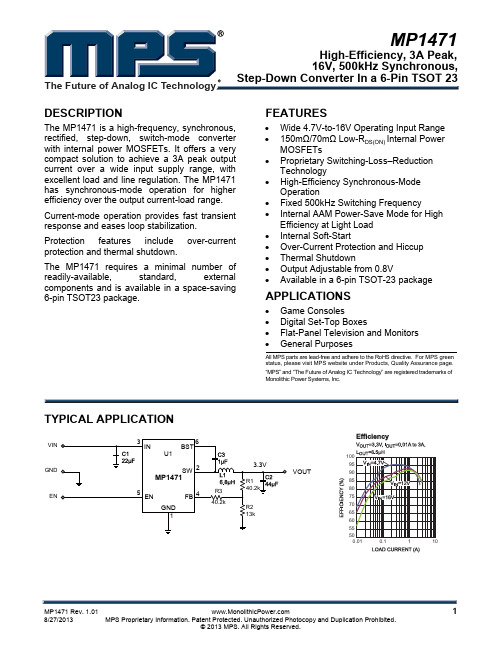
FEATURES APPLICATIONSDESCRIPTIONMute Control TPA3121D2SIMPLIFIED APPLICATION CIRCUITLeft Channel Right Channel10 V to 26 V Shutdown ControlS0267-01TPA3121D2 SLOS537–MAY 200815-W STEREO CLASS-D AUDIO POWER AMPLIFIER•Flat Panel Display TVs •10-W/Ch Stereo Into an 8-ΩLoad From a 24-V Supply•DLP ®TVs •CRT TVs•15-W/Ch Stereo Into a 4-ΩLoad from a 22-V Supply•Powered Speakers•30-W/Ch Mono Into an 8-ΩLoad from a 22-V Supply•Operates From 10V to 26VThe TPA3121D2is a 15-W (per channel),efficient,class-D audio power amplifier for driving stereo •Can Run From +24V LCD Backlight Supply speakers in a single-ended configuration or a mono •Efficient Class-D Operation Eliminates Need speaker in a bridge-tied-load configuration.The for Heat SinksTPA3121D2can drive stereo speakers as low as 4Ω.•Four Selectable,Fixed-Gain SettingsThe efficiency of the TPA3121D2eliminates the need for an external heat sink when playing music.•Internal Oscillator to Set Class D Frequency (No External Components Required)The gain of the amplifier is controlled by two gain select pins.The gain selections are 20,26,32,and •Single-Ended Analog Inputs36dB.•Thermal and Short-Circuit Protection With Auto RecoveryThe patented start-up and shutdown sequences minimize pop noise in the speakers without additional •Space-Saving Surface Mount 24-Pin TSSOP circuitry.Package•Advanced Power-Off Pop ReductionPlease be aware that an important notice concerning availability,standard warranty,and use in critical applications of Texas Instruments semiconductor products and disclaimers thereto appears at the end of this data sheet.DLP is a registered trademark of Texas Instruments.System Two,Audio Precision are trademarks of Audio Precision,Inc.PRODUCTION DATA information is current as of publication date.Copyright ©2008,Texas Instruments IncorporatedProducts conform to specifications per the terms of the Texas Instruments standard warranty.Production processing does not necessarily include testing of all parameters.PVCCLSD PVCCLMUTELINRIN BYPASSAGNDAGND PVCCR VCLAMP PVCCR PGNDL PGNDL LOUT BSL AVCC AVCC GAIN0 GAIN1 BSR ROUT PGNDR PGNDRTPA3121D2SLOS537– These devices have limited built-in ESD protection.The leads should be shorted together or the device placed in conductive foam during storage or handling to prevent electrostatic damage to the MOS gates.PWP(TSSOP)PACKAGE(TOP VIEW)Table1.TERMINAL FUNCTIONSTERMINALI/O/P DESCRIPTION24-PINNAME(PWP)Shutdown signal for IC(low=disabled,high=operational).TTL logic levels with compliance to SD2IAVCCRIN6I Audio input for right channelLIN5I Audio input for left channelGAIN018I Gain select least-significant bit.TTL logic levels with compliance to AVCCGAIN117I Gain select most-significant bit.TTL logic levels with compliance to AVCCMute signal for quick disable/enable of outputs(high=outputs switch at50%duty cycle,low= MUTE4Ioutputs enabled).TTL logic levels with compliance to AVCCBSL21I/O Bootstrap I/O for left channelPVCCL1,3P Power supply for left-channel H-bridge,not internally connected to PVCCR or AVCCLOUT22O Class-D-H-bridge positive output for left channelPGNDL23,24P Power ground for left-channel H-bridgeVCLAMP11P Internally generated voltage supply for bootstrap capacitorsBSR16I/O Bootstrap I/O for right channelROUT15O Class-D-H-bridge negative output for right channelPGNDR13,14P Power ground for right-channel H-bridge.PVCCR10,12P Power supply for right-channel H-bridge,not connected to PVCCL or AVCCAGND9P Analog ground for digital/analog cells in coreAGND8P Analog ground for analog cells in coreReference for preamplifier inputs.Nominally equal to AVCC/8.Also controls start-up time via BYPASS7Oexternal capacitor sizing.AVCC19,20P High-voltage analog power supply.Not internally connected to PVCCR or PVCCLConnect to ground.Thermal pad should be soldered down on all applications to secure the Thermal pad Die pad Pdevice properly to the printed wiring board.2Submit Documentation Feedback Copyright©2008,Texas Instruments IncorporatedProduct Folder Link(s):TPA3121D2ABSOLUTE MAXIMUM RATINGSDISSIPATION RATINGSRECOMMENDED OPERATING CONDITIONS TPA3121D2 SLOS537–MAY2008over operating free-air temperature range(unless otherwise noted)(1)VALUE UNITV CC Supply voltage AVCC,PVCC–0.3to30VV I Logic input voltage SD,MUTE,GAIN0,GAIN1–0.3to V CC+0.3VV IN Analog input voltage RIN,LIN–0.3to7V Continuous total power dissipation See Dissipation Rating TableT A Operating free-air temperature range–40to85°CT J Operating junction temperature range–40to150°CT stg Storage temperature range–65to150°CSE Output Configuration 3.2R L Load resistance(minimum value)ΩBTL Output Configuration 6.4Human body model(all pins)±2kV ESD Electrostatic Discharge Charged-device model(all±500Vpins)(1)Stresses beyond those listed under absolute maximum ratings may cause permanent damage to the device.These are stress ratingsonly,and functional operation of the device at these or any other conditions beyond those indicated under recommended operating conditions is not implied.Exposure to absolute-maximum-rated conditions for extended periods may affect device reliability.PACKAGE(1)(2)T A≤25°C DERATING FACTOR T A=70°C T A=85°C24-pin TSSOP 4.16W33.3mW/°C 2.67W 2.16W(1)For the most current package and ordering information,see the Package Option Addendum at the end of this document,or see the TIwebsite at .(2)This data was taken using1oz trace and copper pad that is soldered directly to a JEDEC standard high-k PCB.The thermal pad mustbe soldered to a thermal land on the printed-circuit board.See the PowerPAD Thermally Enhanced Package application note(SLMA002).MIN MAX UNITV CC Supply voltage PVCC,AVCC1026VV IH High-level input voltage SD,MUTE,GAIN0,GAIN12VV IL Low-level input voltage SD,MUTE,GAIN0,GAIN10.8VSD,V I=V CC,V CC=30V125I IH High-level input current MUTE,V I=V CC,V CC=30V125µAGAIN0,GAIN1,V I=V CC,V CC=24V125SD,V I=0,V CC=30V1I IL Low-level input current MUTE,V I=0V,V CC=30V1µAGAIN0,GAIN1,V I=0V,V CC=24V1T A Operating free-air temperature–4085°CCopyright©2008,Texas Instruments Incorporated Submit Documentation Feedback3Product Folder Link(s):TPA3121D2DC CHARACTERISTICSAC CHARACTERISTICSTPA3121D2SLOS537–MAY T A =25°C,V CC =24V,R L =8Ω(unless otherwise noted)T A =25°C,V CC =24V,R L =8Ω(unless otherwise noted)PARAMETERTEST CONDITIONSMINTYP MAXUNIT V CC =24,V ripple =200mV PP 100Hz –48ksvr Supply ripple rejection dB Gain =20dB 1kHz–52Output power at 1%THD+N V CC =24V,f =1kHz 8P O WOutput power at 10%THD+N V CC =24V,f =1kHz 10Total harmonic distortion +f =1kHz,P O =5W0.04%THD+N noise125µV 20Hz to 22kHz,A-weighted filter,V nOutput integrated noise floor Gain =20dB–78dBV CrosstalkP O =1W,f =1kHz;gain =20dB –70dB Max output at THD+N <1%,f =1kHz,SNRSignal-to-noise ratio 92dB gain =20dBThermal trip point 150°C Thermal hysteresis30°C f OSC Oscillator frequency 250300350kHz Δt mute Mute delay Time from mute input switches high until 120msec outputs mutedΔt unmuteUnmute delayTime from mute input switches low until 120msecoutputs unmuted4Submit Documentation FeedbackCopyright ©2008,Texas Instruments IncorporatedProduct Folder Link(s):TPA3121D2FUNCTIONAL BLOCK DIAGRAMAVCCLINRINMUTEBYPASSGAIN1GAIN0SDBSLPVCCLLOUTPGNDLVCLAMPBSR PVCCRROUTPGNDRAGNDTPA3121D2 SLOS537–MAY 2008Copyright ©2008,Texas Instruments Incorporated Submit Documentation Feedback5Product Folder Link(s):TPA3121D2TYPICAL CHARACTERISTICSf − Frequency − Hz201001k10k T H D +N − T o t a l H a r m o n i c D i s t o r t i o n + N o i s e − %0.0011020k0.1G00110.01f − Frequency − Hz201001k10k T H D +N − T o t a l H a r m o n i c D i s t o r t i o n + N o i s e − %0.0011020k0.1G00210.01f − Frequency − Hz201001k10k T H D +N − T o t a l H a r m o n i c D i s t o r t i o n + N o i s e − %0.0011020k0.1G00310.01f − Frequency − Hz201001k10k T H D +N − T o t a l H a r m o n i c D i s t o r t i o n + N o i s e − %0.0011020k0.1G00410.01TPA3121D2SLOS537–MAY All tests are made at frequency =1kHz unless otherwise noted.TOTAL HARMONIC DISTORTION +NOISETOTAL HARMONIC DISTORTION +NOISEvsvsFREQUENCYFREQUENCYFigure 1.Figure 2.TOTAL HARMONIC DISTORTION +NOISETOTAL HARMONIC DISTORTION +NOISEvsvsFREQUENCY FREQUENCYFigure 3.Figure 4.6Submit Documentation FeedbackCopyright ©2008,Texas Instruments IncorporatedProduct Folder Link(s):TPA3121D2P O − Output Power − W 0.010.111040G005P O − Output Power − W0.010.111040G006−100−90−80−70−60−50−40−30−20f − Frequency − HzC r o s s t a l k − d BG008201001k10k 20kP O − Output Power − W0.010.1110T H D +N − T o t a l H a r m o n i c D i s t o r t i o n + N o i s e − %40G007TPA3121D2 SLOS537–MAY 2008TYPICAL CHARACTERISTICS (continued)All tests are made at frequency =1kHz unless otherwise noted.TOTAL HARMONIC DISTORTION +NOISETOTAL HARMONIC DISTORTION +NOISEvsvsFigure 5.Figure 6.TOTAL HARMONIC DISTORTION +NOISECROSSTALKvsvsOUTPUT POWERFREQUENCYFigure 7.Figure 8.Copyright ©2008,Texas Instruments Incorporated Submit Documentation Feedback7Product Folder Link(s):TPA3121D2−100−90−80−70−60−50−40−30−20 f − Frequency − HzC r o s s t a l k − d BG009201001k10k 20k−100−90−80−70−60−50−40−30−20f − Frequency − HzC r o s s t a l k − d BG010201001k10k 20kf − Frequency − HzP h a s e − °201001k100k10kG0116005004003002001000−100−2000510152025303540G a i n − d Bf − Frequency − HzP h a s e − °201001k100k10kG0126005004003002001000−100−2000510152025303540G a i n − d BTPA3121D2SLOS537–MAY TYPICAL CHARACTERISTICS (continued)All tests are made at frequency =1kHz unless otherwise noted.CROSSTALKCROSSTALKvsvsFREQUENCYFREQUENCYFigure 9.Figure 10.GAIN/PHASEGAIN/PHASEvsvsFREQUENCYFREQUENCYFigure 11.Figure 12.8Submit Documentation FeedbackCopyright ©2008,Texas Instruments IncorporatedProduct Folder Link(s):TPA3121D2V CC − Supply Voltage − V12345678910101112131415P O − O u t p u t P o w e r − WG013V CC − Supply Voltage − V2468101214101214161820222426P O − O u t p u t P o w e r − WG014P O − Output Power − W010203040506070809010001234567E f f i c i e n c y − %G015P O − Output Power − W102030405060708090100024681012E f f i c i e n c y − %G016TPA3121D2 SLOS537–MAY 2008TYPICAL CHARACTERISTICS (continued)All tests are made at frequency =1kHz unless otherwise noted.OUTPUT POWEROUTPUT POWERvsvsSUPPLY VOLTAGESUPPLY VOLTAGEFigure 14.A.Dashed linerepresentsthermallylimitedregion.Figure 13.EFFICIENCYEFFICIENCYvsvsOUTPUT POWEROUTPUT POWERFigure 15.Figure 16.Copyright ©2008,Texas Instruments Incorporated Submit Documentation Feedback9Product Folder Link(s):TPA3121D2P O − Output Power − W0.00.30.60.91.21.53691215I C C − S u p p l y C u r r e n t − AG017P O − Output Power − W0.00.20.40.60.81.01.2510152025I C C − S u p p l y C u r r e n t − AG018−100−90−80−70−60−50−40−30−20−100 f − Frequency − HzP o w e r S u p p l y R e j e c t i o n R a t i o −d BG019201001k10k 20k−100−90−80−70−60−50−40−30−20−10f − Frequency − HzP o w e r S u p p l y R e j e c t i o n R a t i o −d BG025201001k10k 20kTPA3121D2SLOS537–MAY TYPICAL CHARACTERISTICS (continued)All tests are made at frequency =1kHz unless otherwise noted.SUPPLY CURRENTSUPPLY CURRENTvsvsOUTPUT POWEROUTPUT POWERFigure 17.Figure 18.POWER SUPPLY REJECTION RATIOPOWER SUPPLY REJECTION RATIOvsvsFREQUENCYFREQUENCYFigure 19.Figure 20.10Submit Documentation FeedbackCopyright ©2008,Texas Instruments IncorporatedProduct Folder Link(s):TPA3121D2f − Frequency − Hz201001k10k T H D +N − T o t a l H a r m o n i c D i s t o r t i o n + N o i s e − %0.0011020k0.1G02010.01P O− Output Power − W0.010.1110T H D +N − T o t a l H a r m o n i c D i s t o r t i o n + N o i s e − %40G021V CC − Supply Voltage − V05101520253035404550101214161820222426P O − O u t p u t P o w e r −WG023P O − Output Power − W0102030405060708090100024681012E f f i c i e n c y − %G024TYPICAL CHARACTERISTICS (continued)All tests are made at frequency =1kHz unless otherwise noted.TOTAL HARMONIC DISTORTION +NOISETOTAL HARMONIC DISTORTION +NOISEvsvsFREQUENCYFigure 21.Figure 22.OUTPUT POWEREFFICIENCYvsvsSUPPLY VOLTAGEOUTPUT POWERFigure 24.A.Dashed linerepresentsthermallylimitedregion.Figure 23.APPLICATION INFORMATIONCLASS-D OPERATIONTraditional Class-D ModulationScheme+V CC 0 VOutput CurrentOutput Current+V CC 0 V+V CC 0 V+V CC0 V–VCCDifferential Voltage Across SpeakerSupply PumpingThis section focuses on the class-D operation of the TPA3121D2.The TPA3121D2operates in AD mode.There are two main configurations that may be used.For stereo operation,the TPA3121D2should be configured in a single-ended (SE)half-bridge amplifier.For mono applications,TPA3121D2may be used as a bridge-tied-load (BTL)amplifier.The traditional class-D modulation scheme,which is used in the TPA3121D2BTL configuration,has a differential output where each output is 180degrees out of phase and changes from ground to the supply voltage,V CC .Therefore,the differential prefiltered output varies between positive and negative V CC ,where filtered 50%duty cycle yields 0V across the load.The class-D modulation scheme with voltage and current waveforms is shown in Figure 25and Figure 26.Figure 25.Class-D Modulation for TPA3121D2SE ConfigurationFigure 26.Class-D Modulation for TPA3121D2BTL ConfigurationOne issue encountered in single-ended (SE)class-D amplifier designs is supply pumping.Power-supply pumping is a rise in the local supply voltage due to energy being driven back to the supply by operation of the class-D amplifier.This phenomenon is most evident at low audio frequencies and when both channels are operating at the same frequency and phase.At low levels,power-supply pumping results in distortion in the audio output due to fluctuations in supply voltage.At higher levels,pumping can cause the overvoltage protection to operate,which temporarily shuts down the audio output.Gain Setting via GAIN0and GAIN1Inputs INPUT RESISTANCEInputSignalf =12Z Cpi i(1)Several things can be done to relieve power-supply pumping.The lowest impact is to operate the two inputs out of phase180°and reverse the speaker connections.Because most audio is highly correlated,this causes the supply pumping to be out of phase and not as severe.If this is not enough,the amount of bulk capacitance on the supply must be increased.Also,improvement is realized by hooking other supplies to this node,thereby, sinking some of the excess current.Power-supply pumping should be tested by operating the amplifier at low frequencies and high output levels.The gain of the TPA3121D2is set by two input terminals,GAIN0and GAIN1.The gains listed in Table2are realized by changing the taps on the input resistors and feedback resistors inside the amplifier.This input impedance(Z i)to be dependent on the gain setting.The actual gain settings are controlled by ratios of resistors,so the gain variation from part-to-part is small.However,the input impedance from part-to-part at the same gain may shift by±20%due to shifts in the actual resistance of the input resistors. For design purposes,the input network(discussed in the next section)should be designed assuming an input impedance of8kΩ,which is the absolute minimum input impedance of the TPA3121D2.At the higher gain settings,the input impedance could increase as high as72kΩ.Table2.Gain SettingINPUT IMPEDANCEAMPLIFIER GAIN(dB),GAIN1GAIN0(kΩ),TYPICALTYPICAL00206001263010321511369Changing the gain setting can vary the input resistance of the amplifier from its smallest value,10kΩ±20%,to the largest value,60kΩ±20%.As a result,if a single capacitor is used in the input high-pass filter,the–3-dB cutoff frequency may change when changing gain steps.The–3-dB frequency can be calculated using e the Z i values given in Table2.INPUT CAPACITOR,C if =c 12Z C p i i–3 dBf c(2)C =i 12Z f p i c(3)Single-Ended Output Capacitor,C OOutput Filter and Frequency ResponseIn the typical application,an input capacitor (C i )is required to allow the amplifier to bias the input signal to the proper dc level for optimum operation.In this case,C i and the input impedance of the amplifier (Z i )form a high-pass filter with the corner frequency determined in Equation 2.The value of C i is important,as it directly affects the bass (low-frequency)performance of the circuit.Consider the example where Z i is 20k Ωand the specification calls for a flat bass response down to 20Hz.Equation 2is reconfigured as Equation 3.In this example,C i is 0.4µF;so,one would likely choose a value of 0.47µF as this value is commonly used.If the gain is known and is constant,use Z i from Table 2to calculate C i .A further consideration for this capacitor is the leakage path from the input source network (C i )and the feedback network to the load.This leakage current creates a dc offset voltage at the input to the amplifier that reduces useful headroom,especially in high-gain applications.For this reason,a low-leakage tantalum or ceramic capacitor is the best choice.When polarized capacitors are used,the positive side of the capacitor should face the amplifier input in most applications as the dc level there is held at 2V,which is likely higher than the source dc level.Note that it is important to confirm the capacitor polarity in the application.Additionally,lead-free solder can create dc offset voltages,and it is important to ensure that boards are cleaned properly.In single-ended (SE)applications,the dc blocking capacitor forms a high-pass filter with the speaker impedance.The frequency response rolls of with decreasing frequency at a rate of 20dB/decade.The cutoff frequency is determined byf c =1/2πC O Z LTable 3shows some common component values and the associated cutoff frequencies:Table mon Filter ResponsesC SE -DC Blocking Capacitor (µF)Speaker Impedance (Ω)f c =60Hz (–3dB)f c =40Hz (–3dB)f c =20Hz (–3dB)4680100022006470680150083304701000For the best frequency response,a flat-passband output filter (second-order Butterworth)may be used.The output filter components consist of the series inductor and capacitor to ground at the LOUT and ROUT pins.There are several possible configurations,depending on the speaker impedance and whether the output configuration is single-ended (SE)or bridge-tied load (BTL).Table 4lists the recommended values for the filter components.It is important to use a high-quality capacitor in A rating of at least X7R is required.LOUT / ROUTLOUTROUTPower-Supply Decoupling,C SPower Supply RejectionTable 4.Recommended Filter Output ComponentsOutput Configuration Speaker Impedance (Ω)Filter Inductor (µH)Filter Capacitor (nF)422680Single Ended (SE)833220Bridge Tied Load (BTL)822680Figure 27.BTL Filter Configuration Figure 28.SE Filter ConfigurationThe TPA3121D2is a high-performance CMOS audio amplifier that requires adequate power-supply decoupling to ensure that the output total harmonic distortion (THD)is as low as possible.Power-supply decoupling also prevents oscillations for long lead lengths between the amplifier and the speaker.The optimum decoupling is achieved by using two capacitors of different types that target different types of noise on the power-supply leads.For higher-frequency transients,spikes,or digital hash on the line,a good low equivalent-series-resistance (ESR)ceramic capacitor,typically 0.1µF to 1µF,placed as close as possible to the device V CC lead works best.For filtering lower frequency noise signals,a larger aluminum electrolytic capacitor of 470µF or greater placed near the audio power amplifier is recommended.The 470-µF capacitor also serves as local storage capacitor for supplying current during large signal transients on the amplifier outputs.The PVCC terminals provide the power to the output transistors,so a 470-µF or larger capacitor should be placed on each PVCC terminal.A 10-µF capacitor on the AVCC terminal is adequate.These capacitors must be properly derated for voltage and ripple-current rating to ensure reliability.TPA3121D2has good power supply rejection due to the closed-loop architecture;however,it is possible to achieve better performance (if desired)by adding a filter between the PVCC supply and the AVCC supply.The following figures illustrate the improvement that can be obtained by adding a 220Ω,220µF filter before pins 19and 20.−100−90−80−70−60−50−40−30−20−100 f − Frequency − HzP o w e r S u p p l y R e j e c t i o n R a t i o − d BG026201001k10k20k−100−90−80−70−60−50−40−30−20−10f − Frequency − HzP o w e r S u p p l y R e j e c t i o n R a t i o − d BG027201001k10k20kVCCBSN and BSP CapacitorsFigure 29.PSRR Without AVCC FilterFigure 30.PSRR With AVCC FilterFigure 31.Application Schematic with 220-Ω/220-µF AVCC FilterThe half H-bridge output stages use only NMOS transistors.Therefore,they require bootstrap capacitors for the high side of each output to turn on correctly.A 220-nF ceramic capacitor,rated for at least 25V,must be connected from each output to its corresponding bootstrap input.Specifically,one 220-nF capacitor must be connected from LOUT to BSL,and one 220-nF capacitor must be connected from ROUT to BSR.The bootstrap capacitors connected between the BSx pins and their corresponding outputs function as a floating power supply for the high-side N-channel power MOSFET gate-drive circuitry.During each high-side switching cycle,the bootstrap capacitors hold the gate-to-source voltage high enough to keep the high-side MOSFETs turned on.VCLAMP CapacitorTo ensure that the maximum gate-to-source voltage for the NMOS output transistors is not exceeded,one internal regulator clamps the gate voltage.One1-µF capacitor must be connected from VCLAMP(pin11)to ground and must be rated for at least16V.The voltages at the VCLAMP terminal may vary with V CC and may not be used for powering any other circuitry.VBYP Capacitor SelectionThe scaled supply reference(VBYP)nominally provides an AVCC/8internal bias for the preamplifier stages.The external capacitor for this reference(C BYP)is a critical component and serves several important functions.During start-up or recovery from shutdown mode,C BYP determines the rate at which the amplifier starts.The start up time is proportional to0.5s per microfarad.Thus,the recommended1-µF capacitor results in a start-up time of approximately500ms.The second function is to reduce noise produced by the power supply caused by coupling with the output drive signal.This noise could result in degraded power-supply rejection and THD+N.The circuit is designed for a C BYP value of1µF for best pop performance.The input capacitors should have the same value.A ceramic or tantalum low-ESR capacitor is recommended.SHUTDOWN OPERATIONThe TPA3121D2employs a shutdown mode of operation designed to reduce supply current(I CC)to the absolute minimum level during periods of nonuse for power conservation.The SHUTDOWN input terminal should be held high(see specification table for trip point)during normal operation when the amplifier is in use.Pulling SHUTDOWN low causes the outputs to mute and the amplifier to enter a low-current state.Never leave SHUTDOWN unconnected,because amplifier operation would be unpredictable.For the best power-up pop performance,place the amplifier in the shutdown or mute mode prior to applying the power-supply voltage.MUTE OperationThe MUTE pin is an input for controlling the output state of the TPA3121D2.A logic high on this terminal causes the outputs to run at a constant50%duty cycle.A logic low on this pin enables the outputs.This terminal may be used as a quick disable/enable of outputs when changing channels on a television or transitioning between different audio sources.The MUTE terminal should never be left floating.For power conservation,the SHUTDOWN terminal should be used to reduce the quiescent current to the absolute minimum level.USING LOW-ESR CAPACITORSLow-ESR capacitors are recommended throughout this application section.A real(as opposed to ideal)capacitor can be modeled simply as a resistor in series with an ideal capacitor.The voltage drop across this resistor minimizes the beneficial effects of the capacitor in the circuit.The lower the equivalent value of this resistance, the more the real capacitor behaves like an ideal capacitor.SHORT-CIRCUIT PROTECTIONThe TPA3121D2has short-circuit protection circuitry on the outputs that prevents damage to the device during output-to-output shorts and output-to-GND shorts after the filter and output capacitor(at the speaker terminal.) Directly at the device terminals,the protection circuitry prevents damage to device during output-to-output, output-to-ground,and output-to-supply.When a short circuit is detected on the outputs,the part immediately disables the output drive.This is an unlatched fault.Normal operation is restored when the fault is removed.THERMAL PROTECTIONPRINTED-CIRCUIT BOARD (PCB)LAYOUTThermal protection on the TPA3121D2prevents damage to the device when the internal die temperature exceeds 150°C.There is a ±15°C tolerance on this trip point from device to device.Once the die temperature exceeds the thermal set point,the device enters into the shutdown state and the outputs are disabled.This is not a latched fault.The thermal fault is cleared once the temperature of the die is reduced by 30°C.The device begins normal operation at this point with no external system interaction.Because the TPA3121D2is a class-D amplifier that switches at a high frequency,the layout of the printed-circuit board (PCB)should be optimized according to the following guidelines for the best possible performance.•Decoupling capacitors—The high-frequency 0.1-µF decoupling capacitors should be placed as close to the PVCC (pins 1,3,10,and 12)and AVCC (pins 19and 20)terminals as possible.The VBYP (pin 7)capacitor and VCLAMP (pin 11)capacitor should also be placed as close to the device as rge (220-µF or greater)bulk power-supply decoupling capacitors should be placed near the TPA3121D2on the PVCCL and PVCCR terminals.•Grounding—The AVCC (pins 19and 20)decoupling capacitor and VBYP (pin 7)capacitor should each be grounded to analog ground (AGND,pins 8and 9).The PVCCx decoupling capacitors and VCLAMP capacitors should each be grounded to power ground (PGND,pins 13,14,23,and 24).Analog ground and power ground should be connected at the thermal pad,which should be used as a central ground connection or star ground for the TPA3121D2.•Output filter—The reconstruction filter (L1,L2,C9,and C16)should be placed as close to the output terminals as possible for the best EMI performance.The capacitors should be grounded to power ground.•Thermal pad—The thermal pad must be soldered to the PCB for proper thermal performance and optimal reliability.The dimensions of the thermal pad and thermal land are described in the mechanical section at the back of the data sheet.See TI Technical Briefs SLMA002and SLOA120for more information about using the thermal pad.For recommended PCB footprints,at this data sheet.For an example layout,see the TPA3121D2Evaluation Module (TPA3121D2EVM)User Manual,(SLOU189).Both the EVM user manual and the thermal pad application note are available on the TI .。
1Advanced Model-Based-System Design
Lecture3:DriveCyclesandLecture 3: Drive Cycles and Advanced Models
Following a Drive Cycle•Next, we will have the vehicle follow a simple drive cycle.
WilltlldF2•We will use a part called From Workspace(Simulink/Sources) to read in a 2-D variable.
•Using the init file, define a variable called SchCycle. This is two dimensional matrix. _y
•The first column contains the time values and the second column contains the speed values:
Copyright 2009 Rose-Hulman Institute of Technology.2
Following a Drive Cycle•Sch_Cycle =•0 0•100310 0•15 30•20 30•30 40•40 40•55 70•70 70•80 309030•90 30•100 0•120 0
•>> Your init file should look like the following:
Following a Drive Cycle4
Copyright 2009 Rose-Hulman Institute of Technology.3
Following a Drive Cycle•Run the init file to load the variables into memory.
IntheDriverblockaddtheFrom5•In the Driver block, add the From Workspacepart which is located in the Simulink/Sourceslibrary.
6Constant block replaced pwith From Workspaceblock.
Double-click on the From Workspaceblock and modify as shown:
Changed to Sch_Cycle.
Copyright 2009 Rose-Hulman Institute of Technology.4
Following a Drive Cycle•Click the OKbutton to save the changes.•Set the simulation time to run for 120 seconds7seconds.•Run the simulation and view the plot:
8
Copyright 2009 Rose-Hulman Institute of Technology.5
Following a Drive Cycle•We see that the vehicle does follow the specified profile.
•Since there are no mechanical brakes, the 9Sceeeaeoecacabaes,emotor is responsible for slowing the vehicle. ÎRegen braking is working.
•We see the battery discharge as the vehicle accelerates.
Weseethebatterychargeasthevehicle•We see the battery charge as the vehicle decelerates.
Following a Drive Cycle•One question we have is how close does the vehicle follow the drive cycle.
•We need to add a diagnostic output to the 10eeedoaddadagoscoupuoedriver block to display the Sch_Cycle signal.
•We need to add this signal to the Vehicle System Diagnostic bus.
Weneedtodisplaythissignalonthe•We need to display this signal on the same plot as the vehicle speed.
Copyright 2009 Rose-Hulman Institute of Technology.6
Modified Driver Block11Top Level Block Diagram12This part added.Copyright 2009 Rose-Hulman Institute of Technology.7
Top Level –Vehicle System Diagnostic Bus
13
This part added.Display Modifications14
When we run the simulation, we see that the vehicle has a little trouble following the drive cycle.
Copyright 2009 Rose-Hulman Institute of Technology.8
15Advanced Model-Based-System Design
ReadingDriveCyclesinExcelReading Drive Cycles in Excel
Copyright 2009 Rose-Hulman Institute of Technology.9
Drive Cycles•Drive Cycles are available from several sources and in several different formats.
WewilluseExceltostoreourdrivecycles17•We will use Excel to store our drive cycles since Excel can be used to easily modify the cycles.
Drive Cycles•Create a directory called Drive_Cycles in your current working directory.
f18•We will keep all of our drive cycles in this directory.
•Copy the drive cycles that were provided for this class to this directory
Copyright 2009 Rose-Hulman Institute of Technology.10
AVL Drive Cycle19The Sch_Cycle tab contains the time and speed coordinates for the cycle.
Sch Cycle Tab.Time(seconds)Speed (mph)
Drive Cycles•The speed in the Sch_Cycleworksheet is in mph.
Forthemomentallwewilluseisthe20•For the moment, all we will use is the Sch_Cycleinformation for vehicle speed.
•The Excel file contains information for the brake pedal, gear selection, grade, and key on.
Copyright 2009 Rose-Hulman Institute of Technology.11
Drive Cycles•As your model progresses, you may use some of the other signals.
Fornowwewillreadinallofthe21•For now, we will read in all of the information, but we will only use the vehicle speed information.
•We will place the following code in our init file to read in the excel drive cycle file and store it in MATLAB variables.
22%Read a drive cycle contained in an excel spreadsheet.if (exist('fn') == 0)|(fn==0)fn='Drive_Cycles\sch_fu505.xls';elsefn=['Drive_Cycles\',fn];end[fn,pn]=uigetfile('Drive_Cycles\sch*.xls','Specify an Excel Schedule File Name',fn);name=[pn,fn];
Sch_Cycle = xlsread(name, 'Sch Cycle');Sch_Brake_on = xlsread(name, 'Sch Brake On');SchGearon=xlsread(name'SchGearOn');Sch_Gear_on = xlsread(name,Sch Gear On);Sch_Grade = xlsread(name, 'Sch Grade');Sch_Key_on = xlsread(name, 'Sch Key On');%Convert the grade from percent to radians.Sch_Grade(:,2)=atan(Sch_Grade(:,2)/100);