
三速开关使用说明书HONEYWELL
- 格式:pdf
- 大小:191.94 KB
- 文档页数:2


LOW ENERGY SWITCHINGGeneral Technical Bulletin #13 - Low Energy Switching2 Honeywell Sensing and Controle of ContentsPageINTRODUCTION (3)LOW ENERGY SWITCHING (3)MECHANICAL PERFORMANCE (4)Plunger Movement Characteristics (4)Plunger Force vs. Plunger Position................................................................. 5 Circuit Terminology (5)ELECTRICAL PERFORMANCE (6)Insulation Resistance..................................................................................... 6 Dielectric Strength......................................................................................... 6 Switch Resistance......................................................................................... 6 Contact Resistance....................................................................................... 7 Load Resistance........................................................................................... 7 Measurement of Switch Resistance................................................................ 7 Switch Resistance in Application................................................................... 8 Role of Contamination in Switch Resistance................................................... 9 Common Contact Materials..........................................................................10 Common Contact Configurations...................................................................11 Switch Life (12)GENERAL APPLICATION GUIDELINES .....................................................13 Storage, Installation, and Maintenance...........................................................13 Design..........................................................................................................14 Environment.. (15)SUMMARY (15)General Technical Bulletin #13 - Low Energy SwitchingFor application help: call 1-800-537-6945 Honeywell Sensing and Control 3INTRODUCTIONIn today’s age of low energy control, electromechanical switches are more frequently interfacing directly with computers and other low energy driven hardware. Switching low energy loads presents a unique challenge as compared to switching higher energy loads and at times requires an alternative switch design.The purpose of this bulletin is to provide general information about mechanical and electrical performance of electromechanical switches, along with application guidelines for using electromechanical switches in low energy applications.LOW ENERGY SWITCHINGLow energy switching can be described as using a switch to control any component(s) of a circuit where the load that the contacts will switch will not cause an arc to form between the contacts. Common names for these types of circuits are thermocouple load, dry circuit, logic level, etc.The primary concern in the area of low energy switching is contact contamination. Since low energy loads do not arc or burn the contact surface, they also do not arc or burn off the contaminants that may reside on the contact surface. These contaminants may cause erratic switch resistance and can stop current flow. Pay special attention to the General Application Guidelines if the switch is to be used in a low energy application.General Technical Bulletin #13 - Low Energy Switching4 For application help: call 1-800-537-6945 Honeywell Sensing and ControlMECHANICAL PERFORMANCEPlunger Movement Characteristics of a Basic SwitchFree Position: Switch plunger is fully released and common contact is against normally closed contact.Pretravel: Distance from free position to operating point.Operating Point: Common contact transfers from normally closed contact to normally open contact.Overtravel : Distance plunger travels past operating point.Full Overtravel Point : Point at which further plunger depression is prevented by switch mechanism.Release Point: Common contact transfers from normally open contact to normally closed contact.Differential Travel: Distance between operating point and release point.Operating Force: Force required to depress switch plunger to operating point.Full Overtravel Force: Force required to depress switch plunger to full overtravel point.Release force: Force required to allow the plunger to return to release point.The movement of the switch plunger from the free position through the release point is considered one cycle of switch operation.General Technical Bulletin #13 - Low Energy SwitchingFor application help: call 1-800-537-6945 Honeywell Sensing and Control 5Plunger Force vs. Plunger PositionThe graph at the right represents the relationship between plunger travel and plunger force and is of interest when the mechanism used to operate the switch is a force-sensitive device such as a dead weight, a thermostatic bimetal or a gas-filled bellows.For data on a specific switch type, contact the- MICRO SWITCH Application Center at 1-800-537-6945.Circuitry TerminologyPole : The number of completely separate circuits that can pass through the switch at one time.Throw: The number of different circuits that each pole can control.Break: The number of pairs of separated contacts the switch introduces into each circuit it opens.General Technical Bulletin #13 - Low Energy Switching6 For application help: call 1-800-537-6945 Honeywell Sensing and ControlELECTRICAL PERFORMANCEInsulation Resistance Applied voltage divided by the current is the electrical resistance of the insulation. For new switches at commonly used voltages, insulation resistance usually exceeds 100,000 megohms between non-connected terminals and between terminals and switch housing. The voltage does put an electrical stress on the material but does not damage it unless the potential exceeds the dielectric strength of the switch.Dielectric Strength Dielectric strength is the highest electrical potential that an insulating material can withstand without breaking down, i.e., dielectric breakdown. New switches usually have dielectric strength of over 1000 volts with leakage current less than 500 microamps. When the voltage exceeds the dielectric strength, the insulating material is permanently damaged.Insulation Resistance and Dielectric StrengthSwitch Resistance Switch Resistance is the total resistance of the conducting path between the wiringterminals of the switch.Sources of Switch ResistanceGeneral Technical Bulletin #13 - Low Energy SwitchingFor application help: call 1-800-537-6945 Honeywell Sensing and Control 7Typical Pattern of Switch Resistance versus Plunger Position at 6 Volts DC, 0.1 AmpereContact Resistance : The resistance between a pair of closed contacts.Load Resistance : Load resistance affects contact resistance in the following way; if the circuit voltageexceeds the softening or melting voltage of the contact material, the material softens or melts due to I 2R heating. See table below for softening and melting voltage of silver and gold.MaterialApproximateSoftening VoltageApproximate Melting VoltageSilver .09 Volt .37 Volt Gold.08 Volt.43 VoltIf the metal at the contact interface softens or melts, the cross-sectional area of the conducting path between the contacts will depend upon the current. The size of this cross-sectional area determines contact resistance. The higher the current, the greater the cross-sectional area of the bridge and the lower its resistance. If the softening voltage is not reached, the contact resistance is independent of current.Measurement ofSwitch Resistance: Switch resistance should be measured by voltage drop using the same voltage andcurrent as in the circuit in which the switch is to be used. This can be accomplished by connecting the switch in a series circuit consisting of a power supply of the specified voltage, a variable resistor and ammeter.General Technical Bulletin #13 - Low Energy SwitchingConnections for Measurement of Switch ResistanceSwitch Resistancein Application: In the application of snap-acting switches, if the source voltage is at least .5 volts, contact material almost always softens, or melts slightly, at the interface, and switch resistance becomes afunction of current. This leads to the following practical consequences:1. In low current circuits, switch resistance tends to be relatively high. However, low current circuitsusually have high resistance load components. The resistance of the switch usually is such a smallpart of the total resistance of the circuit that switch resistance is not a problem.2. High current circuits usually have low-resistance load components. In high current circuitshowever, switch resistance tends to be low. Again, the resistance is such a small part of the totalresistance of the circuit that switch resistance is not a problem.At source voltages of 0.5 volt or greater, the resistance of a switch during its life will rarely exceed1% of the load resistance. If source voltage is less than 0.5 volt, switch resistance may or may notbe a function of current, depending upon the amount of the source voltage that appears across thecontacts.In general, the maximum allowable switch resistance of a specific application can be defined asfollows: For DC circuits, the maximum allowable switch resistance equals the line voltage divided by the minimum allowable current, minus the load resistance. For AC circuits, the maximum allowable switch resistance equals the line voltage divided by minimum allowable current, multiplied by thepower factor and minus the load resistance.8 For application help: call 1-800-537-6945 Honeywell Sensing and ControlGeneral Technical Bulletin #13 - Low Energy SwitchingFor example, consider a switch in series with a relay coil:• 24 VDC, 5000 ohm coil, operate .004 amp, release .0025 amp.• Without the switch in the circuit, I=.0048• With the switch in circuit, coil will operate at I=.004. Switch resistance will do no harm if it does not reduce the .0048 amp to less than .004 amp• Total resistance that will allow .004 amp flow = R = V/I = 24 volts/.004 amp = 6000 ohms• Therefore, maximum allowable switch resistance = 6000 ohms - 5000 ohms or 1000 ohmsRole ofContamination inSwitch Resistance:There are two general classifications for switch contaminants, particles and films. Particles can becrushed solids that enter the switch during application or assembly. Particles deposit on the contact surface, are crushed between the contacts and can become embedded in the contact material due to contact force. Particles can cause erratic contact during wipe and roll of contacts and, if large orextensive enough, can stop current flow.Films are the second type of switch contaminant, which can be broken into two parts, organic andinorganic. Inorganic films, such as silver oxides or silver sulfides, do not typically cause switchresistance problems at the contacts. Silver oxide is conductive, so it does not represent a problem.Silver sulfide films are brittle and are punctured mechanically due to contact force and wiping action.There are several types of contaminants that can create organic films and cause resistance problems.The most common are flux, organic vapors, and silicones. Flux enters the switch cavity by vapor or is carried into the switch cavity by a cleaning solvent. Flux will increase switch resistance and can stop current flow. To avoid flux contamination: avoid use of activated flux; use flux sparingly; use flux core solder; do not allow liquid flux or flux vapor to enter the switch; use a soldering temperature ofapproximately 550° F (288° C); and, do not use solvents on or near switches - they carry flux residue and other contaminants into the switch. It is not necessary to remove flux residue from terminals.Organic materials, especially organic vapors, can decompose in the arc or I2R heating of the material at the interface between the closed contacts. Carbonaceous deposits can build up over time on thecontact surface and increase the switch resistance.For application help: call 1-800-537-6945 Honeywell Sensing and Control 9General Technical Bulletin #13 - Low Energy SwitchingSilicon is an inorganic element found in many materials. Silicone is an organic material commonlyfound in oils, greases, mold release, cleaning sprays, and potting material. Silica (SiO2), commonly referred to as glass, is transformed from silicone in the presence of electrical energy. Silicones enter the switch as vapor and over time, based on load, rate of actuation, and amount of silicone present, transform into silica. These silica deposits can raise switch resistance and stop current flow. Everyprecaution should be taken in the application to prevent silicone from coming in contact with the inner switch cavity.Common ContactMaterials:• Fine silver. 1.6 ohms/cm, low cost, if kept clean, there is no lower load limit.• 24 karat gold.2.36 ohm/cm, high cost, limited to use in applications with little or no arc energy because of its ductility.• Gold Alloys.Different properties depending on the alloy.• Gold clad over silver.If the load is low energy, it is carried through gold. If the load is arcing, it burns away the gold and is carried through silver contacts. However, a switch that has seen anarcing load should not be used for a low energy load.• Silver Cadmium Oxide.Designed for use in power loads, not recommended for use in loads less than .5 amp and/or 12 volts.The following graph can be used as a general guide for the selection of contact material. The graph indicates 1st choice, 2nd choice, etc. for each current range. Note, the current represented on the X axis is steady-state. Inrush currents from motor loads and lamp loads can be 6 to 10 times steadystate current.General Guide to the Selection of Contact Material10 For application help: call 1-800-537-6945 Honeywell Sensing and ControlFor application help: call 1-800-537-6945 Honeywell Sensing and Control 11 Common ContactConfigurations:Smooth contact. Common contact configurationSerrated contact. The top surface of the contact can be serrated toprovide a series of peaks and valleys. When the switch is operated theraised areas (peaks) tend to scruff or scrape over the mating contactsurface. This self-cleaning discourage buildups of films or particulate foreignmaterial on the raised areas. Even when the minute particles are not totallyremoved, they tend to drop into the valleys where they are less likely tocontaminate the contact interface. Serrated contacts have been effective inimproving electrical continuity in applications ranging from power duty loadsto low current requirements.Bifurcated contacts. The most effective system developed to date.Bifurcated contacts offer some of the same benefits as described forserrated contacts in addition to providing parallel redundancy.Redundancy can also be provided by connecting two or more switches inparallel and actuating them at the same time.NOTE : Not all contact configurations are available on all switch types.For more information regarding the availability of different contactconfigurations on specific switch types, contact the HONEYWELLApplication Center at 1-800-537-6945.12 For application help: call 1-800-537-6945 Honeywell Sensing and ControlSwitch Life: Mechanical life: The life of a switch with no electrical load present.Electrical life: The life of a switch when switching an electrical load.The following graph demonstrates the life of switch at different electrical loads. Switch life depends on such criteria as electrical load, environment, switch mechanism, and other factors particular to the application. As electrical load increases, switch life decreases. Below 1 amp, the electrical life approaches the mechanical life of the switch. For available test data, contact the HONEYWELL Application Center at 1-800-537-6945.GENERAL APPLICATION GUIDELINESStorage, Installation,and Maintenance• Store switch in a clean, reasonably dry environment that does not exceed the rated temperature of the switch.• Install the switch carefully:♦ Do not drill, sand or otherwise modify the switch.♦ Do not overtighten mounting screws. Review packing sheet instructions carefully.♦ If mounting the switch with an adhesive, use extreme care to avoid contaminating the switch interior.♦ Avoid the use of silicone materials to prevent silicone from coming in contact with the interior of the switch. If this is not possible, in low energy applications, use a sealed switch.♦ When soldering leads to terminals, use non-activated flux core solder and a soldering temperature of about 550° F (288° C).♦ Do not use solvents on switches.♦ Do not use commercial contact cleaners on snap-action switches.♦ Do not paint over switch after installation.♦ Do not connect opposite polarity between normally open and closed terminals. When this is done, and when the arc persists after the contacts are fully apart, a short circuit is establishedthrough the arc and hence through the switch.• Chemicals used during maintenance cleaning can degrade switch materials. If the switch cannot be easily removed prior to cleaning and the types of chemicals used for cleaning are known,contact the HONEYWELL Application Center at 1-800- 537-6945 fo r fluid compatibilitydata.For application help: call 1-800-537-6945 Honeywell Sensing and Control 13Design• For advice regarding the choice of a switch for a specific application, contact the HONEYWELL Application Center at 1-800-537-6945.• If low price is an important factor, silver contacts may help reach the objective.• All snap acting electromechanical switches have contact bounce. When the contact closes it bounces, causing the switch to open and close for a period of microseconds before stayingclosed. If contact bounce will be a problem, the circuit must be buffered. The circuit can bebuffered with additional electronic circuitry or with software.• If the load is below melting voltage, gold or gold alloys can be used for an added measure of safety.• Actuate the switch as closely as possible to the extremes of its plunger travel without applying excess force that might damage the switch. For force data, contact theHONEYWELLApplication Center, 1-800-537-6945.• Decide, based on accurate technical information, whether a switch resistance specification is needed and whether its additional cost is justified. If so, on the basis of end use, specify: thevoltage, current, plunger position, sequence of actuation, and measurement, and maximumallowable switch resistance.• When to give switch resistance special attention:♦ When the switch controls a circuit at less than 0.5 volts.♦ When several switches must be connected in series.♦ When a switch is likely to be exposed to contaminating particles or fumes.♦ When an occasional switch closure with the switch resistance exceeding 1% of the load resistance will have negative consequences.• Design the circuit so the switch sees voltage well above the softening voltage of the contact material, e.g., 0.08 volt for gold, 0.09 volt for silver.• Design low voltage circuits with a minimum number of switches in series.• Design the switch circuit to be as insensitive to normal variations of switch resistance as possible.14 For application help: call 1-800-537-6945 Honeywell Sensing and ControlIf additional assurance of low and stable resistance is desired, use bifurcated contacts or connect two or more switches in parallel and actuate them at the same time.Customers should test the switch under conditions simulating end use to verify that it performs asrequired in the application.Environment• Protect unsealed switches from contamination by particles and fumes.• Switches can be sealed to help prevent contamination from entering them. Some common levels of sealing are: dust resistant, drip-proof, water resistant, resilient, and hermetic. In general, themore critical the application and the harsher the environment, the more stringent the sealrequirements.• If the switch is unsealed and a low energy load is involved, a thorough understanding of the environment is required to choose the correct contact material and configuration. Contact theHONEYWELL Application Center at 1-800-537-6945, for help in choosing the propermaterial• If the environment of an unsealed switch contains a significant amount of sulfides (such as decaying organic matter, cardboard, or vulcanized rubber) and moisture, gold or gold-plated contacts canhelp.• If an alien film contaminant (such as paint spray or oil mist) can reach the contacts, gold won't help. Use a sealed switch.SUMMARYContact material, contact configuration, and the degree of environmental protection are importantconsiderations when low energy switching is required. They must be considered, along with otherapplication variables, to determine the proper switch for the application. The most reliable and cost-effective solution to any switch application results from a partnership between the user andHoneywell’s Sensing and Control Division.For further technical information and assistance in determining your total switching requirements,contact HONEYWELL:1-800-537-6945 USA1-800-737-3360 Canada1-815-235-6847 InternationalFAX1-815-235-6545 USAINTERNET********************.comFor application help: call 1-800-537-6945 Honeywell • MICRO SWITCH Sensing and Control 15Helping You Control Your World Honeywell Inc.11 West Spring StreetFreeport, Illinois 61032001008-3-EN IL50 GLO 797 Printed in USA。

电路 电气额定值单刀单掷 A UL/CSA 额定值15A 125250或480VAC; 1/8Hp, 125VAC; 1/4Hp,250VAC; 1/2A 125VDC; 1/4A 250VDC单刀双掷 B UL/CSA 额定值20A 125250或480VAC 10A 125VAC “L”1Hp 125VAC; 2Hp 250VAC; 1/2A 125VDC; 1/4A 250VDC单刀双掷 C UL/CSA 额定值10A 125或250VAC0.3A 125VDC; 0.15A 250VDC单刀双掷 D UL/CSA 额定值10A 125或250VAC0.3A 125VDC; 1/4A 250VDC单刀双掷 E 额定值1A 125VACSingle-Conduit Connect Switch*EX 开关带有列入UL 的用于危险环境的最小外壳外壳中的火焰能道冷却爆炸气体使其在到达外壳外部爆炸气体的环境之前温度低至燃点温度以下打开前盖可以看到用螺相紧固的开关单元EX 开关具有一个或两个导线也在开关体的单侧或双侧EX 开关对液体不密封不建议用于室外或有水浅的环境如果需要这类一茁壮成长可选用CX 或LSX系列特点:• NEMA179• 紧凑坚固的外壳 • 高达20A 的负载能力 • 宽敞的接线空间 • 可从四个侧面固定 • 滚轮摇杆位置360°可调 • 不产生火花的执行杆 • 附带在盖上的螺钉 • ULCSA 认证 • 接地螺钉NEMA 标准: 17和9UL 和CSA 认证: Class1Div.1GroupsB(仅限于800EXH 系列和EXD 系列)C 和D; Class II Div.1GroupsE,F 和G温度范围: -40~71°C电气额定值电气额定值型号Q.F NP.T.max. mm O.T. minD.T. max. mm 顺时针15A SPDT A EX-AR 2.22-5.56 5.56 (8°)90° 0.18 (0.25°) 顺时针20A SPDT B EXA-AR 3.34-8.90 5.56 25° 0.3 (4°)逆进针15A SPDT A EX-AR30 11.1 2.65 25° 0.18(0.25°)顺时针或逆时针15A 低操作力(无回复弹簧)不带安装支架SPDTA EX-AR160.56-- -附加转杆订EX-AR20时需从下图中选择转杆顺时针, 15A SPDT A EX-AR800 2.22-5.56 5.56 90° 0.18(0.25°)逆时针 15A SPDT A EX-AR83011.1 1.65 25° 0.18(0.25°)顺时针 10A DPDT C EX-D-AR-3* 2.22-6.67 6.35 25° 2.77(4°)逆时针 10A DPDT C EXD-AR30-3* 12.2 5.56 25° 2.77 滚轮转杆 6PA5-EX表铜滚轮6PA127-EX尼龙滚轮顺时针1A**SPDTE EXH-AR3 2.22-6.67 5.56 25° 0.64附加 UL,CSA 认证用于 Class1Group B,(氢气环境)逆时针 1A**SPDTE EXH-AR3311.1 1.65 3.525° 0.64不带转杆(选择转杆参见左图)顺时针SPDTA EXH-AR20 0.22Nm 5.56 90° 0.18(0.25°)正交滚轮转杆 6PA131-EX青铜滚轮逆时针其余同上A EXH-AR230 0.22Nm 5.56 90° 0.18(0.25°)单向滚轮转杆 顺时针6PA130-EX 青铜滚轮 逆时针6PA142-EX青铜滚轮顺时针或逆时针的转动方向为从商标面看过去的方面 *带3英尺引线**内部开关单元为真空密封开关带3.2米引线工作特性: O.F.操作力; P.T.-预行程; O.T.过行程; D.T.差动行程可调长度滚轮转杆6PA138-EX尼龙转杆棒式转杆6PA136-EX铝棒可调长度12.5英寸棒式转杆 带1英寸尼龙滚轮滚轮转杆开关选型表形式电气额定值型号 O.F.max. N P.T. max. mm O.T. min D.T. max. mm 顺时针15A SPDT不带安装支架A EX-AR1613 0.56 18° 90° -正交滚轮转杆开关选型表过行程柱塞式开关手动操作开关低力扫描仪转杆开关单向滚轮转杆开关形式电气额定值型号 O.F. N P.T.max. mm O.T. min D.T. max. mm 顺时针15A SPDTA EX-CR 2.22-5.56 5.56 90° 0.18选型表形式电气额定值型号 O.F. N P.T.max. mm O.T. min D.T. max. mm 顺时针15A SPDTA EX-AR128 2.22-5.56 5.56 90° 0.18选型表选型表形式电气额定值型号 O.F. N 3×3.5英寸踏班 SPDT不带安装支架A EX-AR50 11.1选型表形式 电气额定值型号 O.F. max. N P.T.max. mm O.T. min D.T. max. mm O.P.* mm 15A,SPDT A EX-Q 13.34 2.98 4.78 0.1 47.22 20A,SPDT B EXA-Q 8.9 1.27 3.18 0.23 46.0215A, SPDT A EX-Q800 13.34 1.98 4.78 0.1 47.22 附加ULCSA 认 证用于 Class1, Group B, (氢气环境)10A, DPDT C EXD-Q-3** 13.34 3.96 3.58 1.52 46.02 带密封靴10A,SPDTD EX-N15 13.34 1.98 4.78 0.1 52.32公差为±0.06毫米**带3英尺电缆操作特性: O.T.-操作力; P.T.-预行程; O.T.-过行程; D.T.-差动行程形式 电气 额定值 型号O.F.max.N P.T. max.mm O.F. min D.T. max. mm 两个1/2英寸的出线孔 顺时针15A SPDT A 1EX1 2.22 5.56 5.56 0° 0.18 两个1/2英寸的出线孔 顺时针20A SPDT B 1EX1 3.618.90 5.56 25° 0.3 两个3/4英寸的出线孔 顺时针10A DPDT C 4EX13* 2.22 6.67 6.35 25° 2.77双出线孔开关 本页所示的开关为双出线孔式开关便于穿过式接线用户还可利用这一特点将DPDT开关的两路接线分别从不同的出线孔引出外壳尺寸比单出线孔的EX 开关大一些提供了附加的接线空间NEMA双出线孔的EX 开关具有与单出线孔开关相同的密封防爆等级选型表滚轮转杆开关*带3英寸长电缆操作特性: O.F.-操作力; P.T.-预行程; O.T.-过行程; D.T.-差动行程安装支架安装尺寸15PA85EX 用于从顶部底部 15PA86EX 仅用于从顶部固定柱或后部固定EX 塞式开关滚轮转杆式EX 开关也可直接固定用1032UNF 螺钉不带滚轮转杆安装尺寸正交滚轮转杆单向滚轮转杆低操作力棒式手动操作式柱塞式带密封靴柱塞式带双出线孔的开关滚轮转杆。
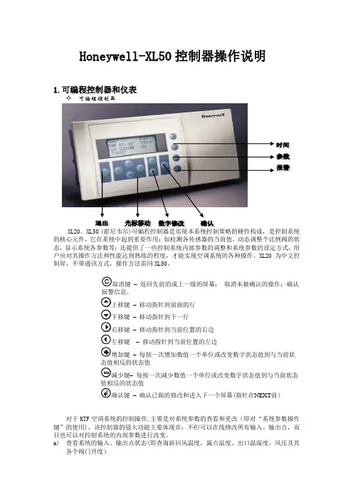
Honeywell-XL50控制器操作说明1.可编程控制器和仪表可编程控制器XL20、XL50 (的核心元件,它在系统中起到重要作用:如检测各传感器的当前值,动态调整个比例阀的状态,显示系统各参数等;还提供了一些控制系统内部参数的调整和系统参数的设定方式,用户应对其操作方法和性能达到熟练的程度,才能实现空调系统的各种操作。
XL20为中文控制屏,不带通讯方式,操作方法雷同XL50。
取消键–返回先前的或上一级的屏幕;取消未被确认的操作;确认报警信息。
上移键–移动指针到前面的行下移键–移动指针到下一行右移键–移动指针到当前位置的右边左移键–移动指针到当前位置的左边增加键–每按一次增加数值一个单位或改变数字状态值到与当前状态值相反的状态值减少键–每按一次减少数值一个单位或改变数字状态值到与当前状态值相反的状态值确认键–确认已做的修改和进入下一个屏幕(指针在NEXT前)对于KTF空调系统的控制操作,主要是对系统参数的查看和更改(即对“系统参数操作键”的使用),该控制器的强大功能主要体现在:不但可以在线修改所有输入、输出点,而且也可以对控制系统的内部参数进行改变。
a)查看系统的输入、输出点状态(即查询新回风温度、露点温度、出口温湿度、风压及其各个阀门开度)♦ 重要说明:对DDC 控制器的操作只能单键进行,严禁同时按压键位,以避免不必要的误操作,以免程序被初始化或删除。
♦ 按下系统“参数”操作键,屏幕出现“请输入你的密码";密码输入才可以修改数据,比如压力等参数的设定等.用户只是查看的话就可以直接进入。
♦ 移动“光标移动"向上键,使光标停留在“****”上,再按下“输入键",通过使用“数据增/减键"和“输入键”逐个将4位密码输入,完毕后屏幕左下角出现‘更改change ’字符;光标移动到change 字符上可以修改进入DDC 修改数据的密码,默认为‘3333’,如更改了密码,用户须牢记更改后的密码,每次参数修改操作都需密码。

If you need detailed product information, or help choosing the right product for your application, see our Interactive Catalog . Use the Interactive Catalog to access the most complete and up-to-date information available.The Interactive Catalog provides an extensive collection of product specifications, application data, and technical literature that can be searched based on criteria you select.This PDF catalog information was published in November 2000.Sensing and Control Honeywell Inc.11 West Spring Street Freeport, IL 61032/sensingSensing and ControlInteractive Catalog...Click this icon to try the Interactive Catalog.Interactive Catalog Supplements Catalog PDFsMOMENTARY (CONTACT SWITCH) OPERATING HEADMomentary CLS Series Cable Pull Limit Switches are designed for signaling applications;they are not to be used as emergency stop devices. (For emergency stop applications, see the Maintained Cable Pull Limit Switches in the Safety Products catalog.)When using direc t ac ting c ontac ts, Momentary Cable Pull Limit Switc hes provide a means to manually force disconnection of a normally closed control circuit by pulling on an attached cable. Momentary switches cause contact transfer if the cable is manually pulled and held.When the c able is released, switc h c ontac ts return to their original state. Momentary switches have either direct-acting contacts or snap-action contacts.Cable length may be up to 200 ft. in a straight line for Single Head switches, and up to 400 ft.(200 ft. in each direction) for Duplex Head switches.TYPICAL DUPLEX HEAD SWITCH INSTALLATIONFEATURESɀOffered in Single Head and Duplex Head versionsɀOptional direct acting contacts enhance reliabilityɀDuplex Head switches cover up to 400ft. cable spans (200 ft. in each direction)ɀSingle Head switches have one normally open auxiliary contact, while Duplex Head switches have up to threenormally open and two normally closed auxiliary contactsɀFour conduit opening thread sizeoptions: 1/2-14 NPT, 20mm, PF1/2 and PG13.5ɀCompact size of Single Head switches fits into tight spacesɀSealed to NEMA 1, 3, 4 and 13ɀSmart Distributed System output available on Duplex version for monitoring only ɀUL listed ɀCSA certified ɀCE certifiedɀTemperature range: –1°to 70°C (30°to 158°F)ɀAvailable with indicatorsɀDuplex versions available with high visibility pilot light TYPICAL APPLICATIONS ɀConveyorsɀPackaging machinery ɀAssembly lines ɀProcess equipment ɀTransfer linesLimit/EnclosedTECHNICAL DATA CLS SERIES SPECIFICATIONSElectricalRate thermal current I th=10 ARate insulation voltage U i=660 VAC/660 VDC Impulse voltage U imp=2.5 kVContact resistance<25 milliohmsOperating rating AC15U =600 V: I =1.2 AU =240 V: I =3 AU =120 V: I =6 ADC13U =250 V: I =0.27 AU =24 V: I =2.8 A UL/CSA A600/Q300MechanicalProtection class NEMA 1, 3, 4 and 13 Mechanical life105operations maximum Temperature Range–1°to 70°C (30°to 158°F) Terminal identification Numbering to EN50013Head/housing material Zinc die castCABLE PULL SWITCH CHARACTERISTICSMomentary Cable Pull Limit Switc hes are offered with a black operating head and a blue body. There is a choice of four different conduit openings: 1/2-14 NPT, 20mm, PF 1/2, and PG13.5. Duplex switc hes have 3 standard conduit openings with two conduit plugs provided.All switches come with a 1NO auxiliary con-tact as standard.An additional auxiliary switch is also avail-able in the Duplex. This auxiliary switch maybe configured as 1NO - 1NC direct acting,2NO - 2NC snap action (monitoring only) or1NO - 1NC with Smart Distributed Systemoutput (monitoring only).Neon and LED indic ators are available. A6 watt incandescent pilot light is availableon the Duplex for high visibility at longdistanc es.SMART DISTRIBUTED SYSTEM OUTPUTVERSIONThe Smart Distributed System Output Ver-sion provides Smart Distributed Systemc ompatible switc h status messaging. Theprimary contact block (NC) must be wired tothe c ontrol c urrent. The auxiliary c ontac tbloc k has been replac ed with the SmartDistributed System circuitry.SINGLE HEAD CLS ORDER GUIDECLS–BODY CODEMODIFICATION CODESA BLUE BODY – PG13.5 1 HEAD ASSEMBLED WITH ACTUATOR TO THE LEFTB BLUE BODY – 1/2 NPT 2 HEAD ASSEMBLED WITH ACTUATOR TO THE FRONTC BLUE BODY – 20MM 3 HEAD ASSEMBLED WITH ACTUATOR TO THE MOUNTING SURFACE D BLUE BODY – PF1/2BASIC SWITCH CODEHEAD CODES 3 1NO-1NC SNAP ACTION (Monitoring Only) B MOMENTARY4 1NO-1NC DIRECT ACTING5 1NO-1NC DIRECT ACTING 240V NEON INDICATOR6 1NO-1NC DIRECT ACTING 120V NEON INDICATOR7 1NO-1NC DIRECT ACTING 24V LED INDICATORNotes:ɀLeave the MODIFICATION CODE blank if a modification is not required.ɀStandard head orientation is with actuator to the right.ɀUnit may be field modified.EXAMPLE CATALOG LISTING Catalog ListingDescriptionCLSD4B-1Single Head Cable Pull Limit Switch, Blue Body – PF 1/2, 1NO - 1NC Direct Acting, Momentary, Head assembled with actuator to the leftDUPLEX HEAD 2CLS ORDER GUIDE2CLS–BODY CODEMODIFICATION CODESA BLUE BODY – PG13.5B BLUE BODY – 1/2 NPTC BLUE BODY – 20MMD BLUE BODY – PF1/2(See chart below for numbered modification codes.)PRIMARY BASIC SWITCH CODE – LEFT 1 1NO – 1NC DIRECT ACTING OPERATING HEADB MOMENTARY, BOTH SIDESINDICATOR – PILOT LIGHT CODE A 120V – 6W RED PILOT LIGHT B 120V NEON INDICATOR C 240V NEON INDICATOR D 24V LED INDICATORAUXILIARY BASIC SWITCH CODE – RIGHT 1 1NO – 1NC DIRECT ACTING3 2NO – 2NC (DPDT) SNAP ACTION (Monitoring Only)4 1NO – 1NC WITH SDS OUTPUT (Monitoring Only)9 NO SWITCHNotes:ɀNo numbered modification code indicates both heads oriented to side (Duplex Head).ɀStandard Conduit openings are left, center, and right with two conduit plugs furnished.ɀLeave the INDICATOR – PILOT LIGHT CODE blank if a pilot light is not required.ɀLeave the HEAD ORIENTATION NUMBERED MODIFICATION CODE blank if not required. Do not enter zero.EXAMPLE CATALOG LISTING Catalog ListingDescription2CLSB1B1-3Duplex Head Cable Limit Switch, Blue Body – 1/2 NPT, 1NO – 1NC Direct Acting, Momentary – Both Sides, 1NO – 1NC Direct Acting, No Pilot Light, Left Head Front – Right Head SideHEAD ORIENTATIONNUMBERED MOD CODES MOD CODELEFT HEAD RIGHT HEAD 1FRONT FRONT 2FRONT REAR 3FRONT SIDE 4REAR FRONT 5REAR REAR 6REAR SIDE 7SIDE FRONT 8SIDEREARMOUNTING DIMENSIONS (For reference only)INSTALLATION HARDWAREɀAircraft cable precut to 25, 50, 100, 150 and 200 feet lengthsɀLockout attachmentɀEnd springs for long cable spans to compensate for temperature variations ɀInstallation hardware kit supports cable installations of 25 ft. and 50 ft.INSTALLATION HARDWARE ORDER GUIDECatalog Listings DescriptionCLSZC125 ft. Red Aircraft Cable, finished cable dia. 0.187 inCLSZC250 ft. Red Aircraft Cable, finished cable dia. 0.187 inCLSZC3100 ft. Red Aircraft Cable, finished cable dia. 0.187 inCLSZC4150 ft. Red Aircraft Cable, finished cable dia. 0.187 inCLSZC5200 ft. Red Aircraft Cable, finished cable dia. 0.187 inCLSZ1S End SpringCLSZ00Installation Kit includes: 4 thimbles, 8 wire rope clamps, 1 turnbuckle (w/lock nuts), 9 eyebolts (w/hardware),1 endspring, 1 conduit fittingNotes:1. Eyebolts should be spaced 1.8 to2.4 m (6 to 8 ft.) apart.2. One used for each 7.5 m (25 ft.) of cable span.Limit/Enclosed。