滚刀设计
- 格式:ppt
- 大小:830.00 KB
- 文档页数:32
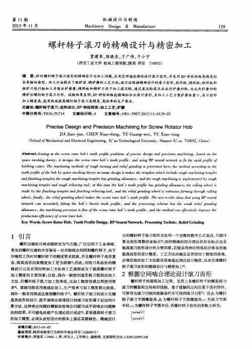
圆顶翅片滚刀的设计开发及其装配田冬龙武宝林张牧沈铭乾(天津工业大学机械工程学院天津 300387)摘要:本文通过对圆顶翅片散热带成形特点的分析研究,利用滚切成型原理开发出一种效率高、精度高、快速设计的翅片滚刀设计方法,并对滚刀的设计理论及成型原理进行阐述,最后以一种类型翅片的刀具为例进行滚刀的设计建模,并经ANSYS仿真从而验证本设计的正确性。
关键词:散热器;圆顶翅片;滚刀;设计理论;装配The Design and Assembly of Dome-topped Fin HobTian Donglong Wu Baolin Shen Mingqian(College of Mechanical Engineering, Tianjin Polytechnic University, Tianjin, 300387)Abstract:By analyzing and researching the forming characteristicsof the dome-topped fin’s radiating corrugated ribbon , al so by combining with roll-type principle, the thesis develops a rapid design hob fin design method with high efficiency and high precision. After elaborating the hob’s design philosophy and molding principle, the authors design and establish a three-dimensional modal and take one of which as a model of the hob . In the end, the thesis verifies the validity and serviceability of the design by the ANSYS simulation.Key words: radiator; dome-topped fins; hob ;design; assembly1 前言翅片是汽车水箱、中冷器以及汽车空调等的重要组成部分,其质量的优劣直接影响到散热效果。

战我,托砰2002.7 塔静宁, 邓效忠, 丁浩 (洛阳工学院,河南洛阳471039)
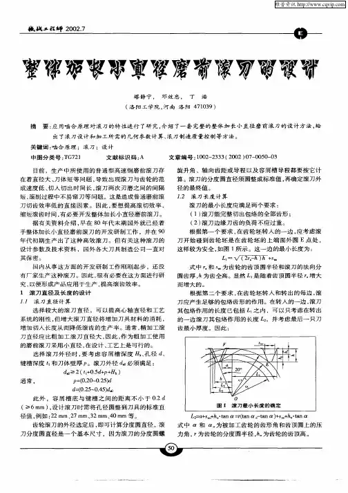
摘要:应用啮合原理对滚刀的特性进行了研究,介绍了一套完整的整体加长小直径磨前滚刀的设计方法,给 出了滚刀设计和加工所需的几何参数计算、滚刀制造质量控制等方法。 关键词:啮合原理;滚刀;设计 中图分类号:TG721 文献标识码:A 文章编号:1002—2333(2002)07—0050—03
目前,生产中所使用的普通型高速钢磨前滚刀存 在着直径大、刀体短等问题,导致出现滚刀与齿轮的范 成速度低、切入切出时间长,滚刀两次刃磨之间的间隔 短,滚削过程中不易窜刀等问题。这是造成普通磨前滚 刀切齿效率低的直接因素。因此,要想提高滚切效率, 缩短滚齿时间,有必要开发整体加长小直径磨前滚刀。 据有关资料介绍,早在8O年代末期国外就已经着 手整体加长小直径磨前滚刀的开发研制工作,并在9O 年代初期生产出了这种高效滚刀。但有关这种滚刀的 设计参数及技术资料,国外各大刀具制造公司一直对 其保密。 国内从事这方面的开发研制工作刚刚起步,还没 有厂家生产这种滚刀。因此,很有必要在这方面进行研 究,以便形成产品应用于生产,提高滚齿效率。 1滚刀直径及长度的设计 J.J滚刀直径计算 选择较大的滚刀直径,可以提高心轴直径和工艺 系统的刚性,但增大滚刀直径将增加刀具材料的消耗, 增加切入长度从而降低滚齿的生产率。通常,精加工滚 刀直径应比粗加工滚刀直径大,因此,作为粗加工使用 的磨前滚刀采用小直径,在设计、工艺上是可行的。 选择滚刀外径时,要考虑容屑槽深度 、孔径d、 键槽深度t-和刀体壁厚P。滚刀外径d 必须满足: d ≥2(tl+0.5d+P+日k) 通常, p=(0.20-0.25)d d=(0.25-0.45)d由 此外,容屑槽底与键槽之间的距离不小于0.2 d (≥6 mm),设计滚刀时需将孔径圆整到刀具的标准直 径值,例如:22 mm、27 mm、32 mm、40 mm等。 齿轮滚刀的外径选定后,即可计算分度圆直径。滚 刀分度圆直径是一个基本尺寸,因为滚刀的分度圆螺 50 旋升角、轴向齿距或导程以及容屑槽导程都要按它计 算。滚刀的分度圆直径须圆整成标准值,再确定滚刀外 径的最终值。 J.2滚刀长度计算 滚刀的最小长度应满足两个要求: (1)滚刀能完整切出包络的全部齿形; (2)滚刀边缘刀齿的负荷不应过重。 根据第一个要求,在齿轮坯转入的一边,应考虑滚 刀开始碰到齿轮坯是在齿轮坯的上端面外圆E点处, 这样较为安全,如图1所示。这一边的最小长度为: Ll一、/(2r,-h)h 式中 和S 为齿轮的齿顶圆半径和滚刀的法向分 圆齿厚,h为齿全高。显然L-是随着齿顶圆半径 增大 而增大的。 根据第二个要求,在齿轮坯转入和转出的每边,滚 刀应产生足够的包络齿形的作用。在转入的一边,滚刀 其包络作用的长度已包括Lt之内,可以只考虑在转出 的一边滚刀其包络作用的长度L:,并考虑最后一只刀 齿最小厚度。因此:
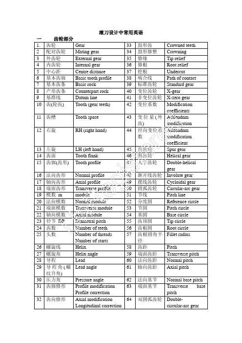
滚刀设计中常用英语一、 齿轮部分 1. 齿轮 Gear 33鼓形齿 Crowned teeth 2 配对齿轮 Mating gear 34 鼓形修整 Crowning 3 外齿轮 External gear 35 修缘 Tip relief 4 内齿轮 Internal gear 36 修根 Root relief 5 中心距 Centre distance 37 挖根 Undercut 6 基本齿廓 Basic tooth profile 38 啮合线 Path of contact 7 基本齿条 Basic rock 39 标准齿轮 Standard gear 8 产形齿条 Counterpart rock 40 变位齿轮 X-gear 9 基准线 Datum line 41 非变位齿轮 X-zero gear 10 齿(轮齿) Tooth (gear teeth) 42 变位系数 Modification coefficients 11 齿槽 Tooth space 43 变位量(外齿)Addendnm modification 12 右旋RH (right hand)44径向变位系数 Addendnm modification coefficient 13 左旋 LH (left hand) 45 直齿轮 Spur gear 14 齿面Tooth flank 46 斜齿轮 Helical gear 15 齿廓(齿形) Tooth profile 47人字齿轮Double-helical gear16 法向齿形 Normal profile 48 渐开线齿轮 Involute gear 17 轴向齿形 Axial profile49 摆线齿轮 Cycloidal gear 18 端面齿形 Transverse profile 50 圆弧齿轮 Circular-arc gear 19 模数 m module51 节线 Pitch line20 法向模数 Normal module 52 分度圆 Reference circle 21 端面模数 Transverse module 53 节圆 Pitch circle 22 轴向模数 Axial module 54 基圆 Base circle 23 径节 DP Diametral pitch 55 齿顶圆 Tip circle 24 齿数 Number of teeth 56 齿根圆 Root circle 25 头数Number of threads Number of starts57 齿根圆角半径 Fillet radius 26 螺旋线 Helix 58 齿距 Pitch27 螺旋角 Helix angle 59 端面齿距 Transverse pitch 28 导程 Lead 60 法向齿距 Normal pitch 29 导程角(螺纹升角) Lead angle 61 轴向齿距 Axial pitch30 压力角 Pressure angle 62 法向基节 Normal base pitch 31 齿廓修形 Profile modificationProfile correction63 端面基节Transverse base pitch32齿向修形 Axial modificationLongitudinal correction64双圆弧齿轮 Double-circular-arc gearUn Re gi st er ed65 公法线长度 Base tangent length 94 基圆螺旋角 Base helix angle66 分度圆直径 Reference diameter 95 基圆导程角 Base lead angle 67 节圆直径 Pitch diameter 96 顶隙 Bottom clearance 68 基圆直径 Base diameter 97 圆周侧隙 Circumferential backlash69 顶圆直径 Tip diameter 98 法向侧隙 Normal backlash 70 根圆直径 Root diameter 99径向侧隙 Radial backlash 71 全齿高 Tooth depth 100 渐开线 Involute 72 工作高度 Working depth 101 蜗杆 worm 73 齿顶高 Addendum 102 蜗轮 Worm wheel 74 齿根高 Dedendum 103 圆柱蜗杆 Cylindrical worm 75弦齿高Chordal height104阿基米德蜗杆(ZA)Straight sided axial worm ,ZA- worm 76 固定齿高 Constant chordal height 105 渐开线蜗杆 (ZI)Involute helicoid worm ,ZI - worm 77 齿宽 facewidth 106 法向直廓蜗杆(ZN) Straight sided norma worm ,ZN 78 齿厚 Tooth thickness107锥面包络圆柱蜗杆(ZK) Milled helicoid worm ,ZK - worm , 79 法向齿厚Normal tooth thickness 108圆弧圆柱蜗杆(ZC) Arc-contact worm , Hollow flank worm ,ZC - worm 80 端面齿厚Transverse tooth thickness81 端面基圆齿厚 Transverse base thickness成品公法线长Final WK 82 法向基圆齿厚Normal base thickness成品渐开线起始圆直径 Form Diameter 83 弦齿厚(端面弦齿厚) Transverse chordal tooth thickness不,超出 Out of 84 法向弦齿厚 Normal chordal tooth thickness渐开线起始圆直径 TIF 85 固定弦齿厚 Constant chord 86 槽宽(端面齿槽宽)Transverse spacewidth87 法向齿槽宽 Normal spacewidth 88 压力角 Pressure angle 89 齿形角 Normal pressure angle 90 法向压力角 Normal pressure angle 91 任意点 At a point 92 端面压力角 Transverse pressure angle93 啮合角 Working pressure angleUn Re gi st er ed二、滚刀部分 1 滚刀 Hob 35 倒棱滚刀 Chamfering hob 2 齿轮滚刀 Gear hob36 铲齿滚刀 Form-relieved hob 3 小模数齿轮滚刀Fine pitch gear hob 37 圆弧齿轮滚刀Circular-arc gear hob4 单头滚刀 Single thread hob , Single start hob38 硬质合金滚刀Carbide hob5 多头滚刀 Multiple thread hob , Multiple start hob 39 尖齿滚刀Profile relieved hob6 右旋滚刀 Right hand hob 40 双头滚刀 Double thread hob 7、 左旋滚刀 Left hand hob 41 摆线滚刀 Cycloidal gear hob 8 直槽滚刀 Straight gash hob 42 定装滚刀 Single position hob 9 斜槽滚刀 Helical gash hob 43 标准滚刀 Standard hob 10 整体滚刀 Solid hob44 定装滚刀 Single position hob 11镶片滚刀Inserted blade hob , Clamped blade hob 45 滚柱链轮滚刀 Roller chain sprocket hob 12 孔式滚刀 Arbor type hob , Shell type hob 46 无声链轮滚刀 Silent chain sprocket hob 13 杆式滚刀 Shank type hob 47 齿顶 Top 14 圆磨法滚刀 Built-up hob 48 齿根 Root 15 铲磨法滚刀 Ground hob 49 齿面 Tooth flank 16 不铲磨滚刀 Unground hob 50 顶刃 Top cutting edge 17 组合式滚刀 Multi-section hob 51 右齿面 R. tooth flank 18 前角滚刀 Raked hob 52 左齿面 L. tooth flank 19 切顶滚刀 Topping hob53 齿顶圆弧 Tip radius 20 半切顶滚刀 Semi- topping hob 54 齿顶全圆弧 Full top radius 21 不切顶滚刀 No-topping hob55 切入齿高 Cutting drpth 22 凸角滚刀 Protuberance type hob 56 基本齿廓 Basic tooth profile 23 修缘滚刀Modified tooth profile hob57 凸角 Protuberance 24 特形滚刀Hob for special profile 58 触角 Lug25 粗切滚刀 Roughing hob 59 前面偏位 Rake offset 26 精切滚刀 Finishing hob 60 铲背量 Cam rise27 剃前滚刀 Pre-shaving hob 61 螺纹升角 Tooth lead angle 28 磨前滚刀 Pre-grinding hob 62 槽数 Number of gashes 29 花键滚刀 Spline hob63 齿根圆弧 Fillet radius30 蜗轮滚刀 Worm wheel hob 64 产形螺旋面 generating helicoid 31 链轮滚刀 Sprocket hob65 铲齿 Relief 32 带轮滚刀 Timing pulley hob 66 前角 Rake angle33渐开线花键滚刀Involute spline hob67切削锥 Starting protion of a hob34 矩形花键滚刀 Straight sided spline hob68头数Number of threads Number of startsUn Re gi st er ed69 齿高Tooth depth 70 全齿高 Whole depth 71 上齿高 Addendum depth 72 下齿高 Dedendum depth73 工作齿高 Working depth of tooth 74 法向齿形 Normal profile 75 轴向齿形 Axial profile 76 节线 Pitch line 77 法向齿距 Normal pitch 78 轴向齿距Axial pitch80 材料、硬度 Material 、 Hardness81 孔径Bore diameter 82轴台径向跳动Radial run-out on hub dia.83 轴台端面跳动Axial run-out on hub face84 刀齿径向跳动Radial run-out on teeth tips85 刀齿前面径向性Radial alignment of gashover cutting depth 86 容屑槽等分误差Adjacent gashspacing error 87 容屑槽等分累积误差Accumulativegash spacing error 88 齿前面与内孔轴线平行度Gash lead erroe (Straightgash hob only )89 齿形误差Tooth profile error 90 齿厚偏差Tooth thickness error 91 全齿高偏差 whole depth error92 齿距偏差Single pitch error 93 三亇齿距的累积误差 Three pitches errorUn Re gi st er ed。
矿产资源开发利用方案编写内容要求及审查大纲
矿产资源开发利用方案编写内容要求及《矿产资源开发利用方案》审查大纲一、概述
㈠矿区位置、隶属关系和企业性质。
如为改扩建矿山, 应说明矿山现状、
特点及存在的主要问题。
㈡编制依据
(1简述项目前期工作进展情况及与有关方面对项目的意向性协议情况。
(2 列出开发利用方案编制所依据的主要基础性资料的名称。
如经储量管理部门认定的矿区地质勘探报告、选矿试验报告、加工利用试验报告、工程地质初评资料、矿区水文资料和供水资料等。
对改、扩建矿山应有生产实际资料, 如矿山总平面现状图、矿床开拓系统图、采场现状图和主要采选设备清单等。
二、矿产品需求现状和预测
㈠该矿产在国内需求情况和市场供应情况
1、矿产品现状及加工利用趋向。
2、国内近、远期的需求量及主要销向预测。
㈡产品价格分析
1、国内矿产品价格现状。
2、矿产品价格稳定性及变化趋势。
三、矿产资源概况
㈠矿区总体概况
1、矿区总体规划情况。
2、矿区矿产资源概况。
3、该设计与矿区总体开发的关系。
㈡该设计项目的资源概况
1、矿床地质及构造特征。
2、矿床开采技术条件及水文地质条件。
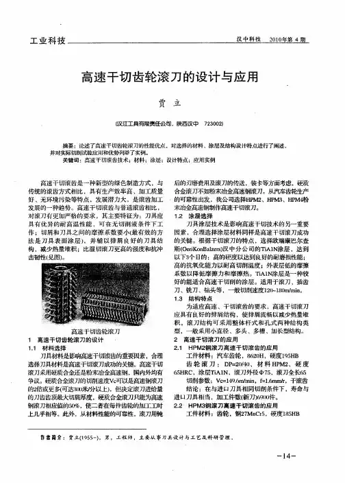
盾构机滚刀北京固本科技有限公司胡建平盾构机滚刀布置和盾构机滚刀说形状在盾构机设计中是非常重要的内容。
刀具布置方式及刀具形状是否适合应用工程的地质条件,直接影响到盾构机的切削效果、出土状况和掘进速度。
1 盾构机滚刀工作安装在刀盘上的盘形滚刀在千斤顶的作用下紧压在岩面上,随着刀盘的旋转,盘形滚刀一方面绕刀盘中心轴公转,同时绕自身轴线自转。
滚刀在刀盘的推力、扭矩作用下,在掌子面上切出一系列的同心圆沟槽。
当推力超过岩石的强度时,盘形滚刀刀尖下的岩石直接破碎,刀尖贯入岩石,形成压碎区和放射状裂纹;进一步加压,当滚刀间距S满足一定条件时,相邻滚刀间岩石内裂纹延伸并相互贯通,形成岩石碎片而崩落,盘形滚刀完成一次破岩过程。
2 影响盾构机滚刀破岩效率的因素:根据以往工程实践及试验数据,影响盾构机滚刀破岩效率的因素有:1) 脆性/塑性:是对抗压强度、抗拉强度的综合评价,适用于抗压强度较大(小),而抗拉强度较小(大)岩石。
有关文献资料显示在同样条件下,脆性岩体在挤压阶段所需时间远远小于塑性岩体(约八分之一)。
2) 耐磨性:本指标直接关系到盾构机掘进效率,是承包商进行刀具寿命及备品估算、工期筹划的主要依据。
根据国外资料统计在耐磨性小的岩石中,更换刀具时间占总停工时间的3%,而在高耐磨性岩石中有20%之多;以每掘进1米时间计算,耐磨性小的岩石为0.02~0.05 hr/m,而高耐磨性岩石则可高达0.2hr/m。
3.双刃盾构机滚刀刀具的磨损及原因:(1)正常磨损刀具的正常磨损是指刀圈的磨损量超过了规定值,磨损量可用专用的量具进行测量。
2)刀圈偏磨如果滚刀在掘进工作面不转动,由于刀圈和掘进工作面的相对运动就会形成刀圈的偏磨。
由于中心区滚刀线速度较小,承受载荷较大,中心区滚刀容易出现此现象。
3)刀圈挡圈磨损或脱落挡圈是由两个半圆的钢环安装在滚刀轴的卡槽里焊接成一个完整的圆环,其作用是防止刀圈从滚刀轴上脱落,一旦刀圈挡圈脱落或焊接处磨损严重,就应该更换刀具。
滚刀工作原理分析盘形滚刀简称盘刀,是隧道掘进机滚压破岩常用的一种刀具型式,典型的盘刀一般由刀圈、轮毂和轴组成;盘形滚刀在各类隧道掘进机上使用非常广泛,主要用于全断面岩石隧道掘进机、盾构及顶管设备;过去盘形滚刀主要用于全断面岩石隧道掘进机刀盘破岩,随着隧道及地下工程的快速发展,所遇到地层复杂性逐渐增加,开始在盾构刀盘上使用盘刀同时布置切刀和滚刀,形成所谓的复合式盾构,以应对各种软硬不均或富水地层,如砂卵砾石地层、风化岩地层及越江、跨海隧道的高水压地层_1;实践证明,这种盾构对地层具有良好的适应性,大大拓展了盾构的适用范围;国际上现在有研发全能隧道掘进机的趋势,复合式盾构应该是全能隧道掘进机的一种雏型;1 盘形滚刀的受力及破岩机理每把盘形滚刀在切割岩石的过程中,刀刃与岩石之间都存在3个方向的相互作用力:1法向推压力FN,指向开挖面,由刀盘的推力提供;2切向滚动切割力FR,指向滚刀切向,由刀盘转矩提供;3滚刀边缘的侧向力FIJ,由滚刀对岩石的挤压力和刀盘旋转的离心力所产生,指向刀盘中心,其数值较小,与其它2个力不属于同一数量级,一般不考虑;3个方向的作用力见图1;切向滚动切割力主要取决于推力、切深及滚刀直径;盘刀直径一定,切深越大,所需滚动切割力越大;切深确定时,滚动切割力随盘刀直径的增大而减小;刀盘工作时,滚刀先与开挖面接触,在推力作用下紧压在岩面上,随着刀盘的旋转,盘形滚刀一方面绕刀盘中心轴公转,同时绕自身轴线自转;盘形滚刀在刀盘的推力和转矩共同作用下,在掌子面上切出一系列同心圆沟槽;刀盘旋转并压人岩石的过程中,盘形滚刀对岩石将产生挤压、剪切、拉裂等综合作用,首先在刀刃下会产生小块破碎体,破碎体在刀刃下被碾压成粉碎体,继而被压密形成密实核,随后密实核将滚刀压力传递给周围岩石,并产生径向裂纹,其中有一条或多条裂纹向刀刃两侧向延伸,到达自由面或与相邻裂纹交汇,形成岩石碎片,整个过程如图2所示;由此形成的岩渣由破碎体、粉碎体及岩石碎片组成,各部分的组成比例取决于岩石性质、刀圈几何尺寸、推压力及刀问距;图1 滚刀受力示意图图2 滚刀破岩原理示意图2 盘形滚刀在刀盘上的布置布刀方式分析盘形滚刀在刀盘上的布置应满足一定的力学和几何学规律,布置时一般应满足:1尽可能使滚刀及刀盘受力均匀,使作用在大轴承上的径向载荷为零;2使前面的刀具能够为后面的刀具提供破岩临空面,形成前后滚刀顺次破岩,如图3所示;图3 滚刀顺次破岩原理因此,盘形滚刀在刀盘上一般按单螺旋线或双螺旋线模式,相邻滚刀按一定相位差布置;如R0bbins型和Java型掘进机的中心刀都布置在同一直线上;Robbins型掘进机正刀和边刀都以相邻2把刀为一组呈对称布置相位角相差180°,相邻2组刀具沿刀盘轴线旋转9 0°;而Java型掘进机正刀和边刀亦以对称布置为原则,但相邻刀具相隔160~~165°;盘形滚刀通常有单刃、双刃及三刃3种形式;盘形滚刀在刀盘上的布置应便于形成顺次破岩,即前一把滚刀先形成较好的切割轨迹及延伸裂纹,后一把滚刀到达时产生的裂纹将终止于前把滚刀形成的裂纹即裂纹贯通、形成岩片;由于双刃和三刃滚刀不能较好地满足所有滚刀顺次破岩的要求,且容易产生不均匀磨损,造成刀具受力恶化及刀具浪费,应尽可能选用单刃滚刀,边刀也应采用单刃滚刀;但为了节约刀盘空间,无论盾构还是掘进机,在刀盘中心大都布置双刃或三刃滚刀;刀间距的确定原则及方法无论是采用哪种方式布置刀具,刀间距都是首要考虑的技术问题之一;刀间距的考虑有两种方式:1在同一台机器上刀间距不变,以改变刀盘推力来适应岩石强度的变化;2在同一刀盘上增减刀具数量或改变每把滚刀上的刀圈数来改变刀间距,以适应岩石强度;第一种考虑方式简单且实用性强,应用较多;刀间距的确定主要取决于开挖岩层的情况及岩石的种类与强度等,其与岩石强度的关系见图4;按照剪切破岩理论,破岩模式如图5所示;由图可知,当刀盘旋转一周,滚刀的切入深度为PR,则按剪切破岩理论,破裂宽度a= PRtanα,要使同一安装半径上的盘形滚刀在刀盘旋转一周的切深相等,切破岩量相同,在相邻滚刀之间就不应存在累积岩脊;因此为保证岩石切割的条件,刀间距应为:S≤2a+b=2PR/tanα+b 1式中S——刀间距;PR——切人深度;α——岩石压裂角,一般在18~30°左右;a——岩石破裂宽度;b——刀圈宽度,与刀圈形式及刀圈直径有关;盘形滚刀布置间距计算举例见表1;按照上述刀间距计算理论,并考虑刀盘空间,在混合地层中掘进时,刀间距的选择原则一般为:1中心刀较少按最优刀间距布置,它们往往以比较小的刀间距布置,以补偿掘进过程中滚刀可能遇到的困难切割条件;2正刀的刀间距在50~120mm之问,对于软岩层取大值,硬岩层取小值;3隧道以软岩为主并有少量硬岩时,刀间距按软岩选择,掘到硬岩地段时,可以慢速掘进;4隧道以硬岩为主并有中硬岩时,刀间距按二者兼顾原则选择;如石灰岩地层的刀间距取80mm,花岗岩地层取50mm,在综合布置时刀间距取70mm为宜;5边刀处于刀盘外缘,速度很高,磨损严重,很少按最优刀间距布置;边刀的刀间距从邻近正刀开始,向外缘逐渐减少,最后2把相邻边刀的刀间距弧长一般为20~25mm,最后一把边刀的刀倾角一般为70°;边刀的布置采用圆弧过渡,过渡区的曲率半径及边刀数量取决于掘进机直径的大小;对于小直径掘进机,曲率半径为300~350rnm,边刀数为6~8把;对于大直径掘进机,曲率半径为600~650mm,边刀数为15~18把;随着滚刀的高强度、耐磨性等技术的综合利用,滚刀的切深得到了很大的提高;但此时为了达到所需的临界推力,需相应地扩大刀问距,否则会使滚刀处于前最优区工作;这也可理解为,采用较宽的刀间距后,为使滚刀处于最优间距下工作,必须相应地增加单把滚刀的推压力;在比切深不变的情况下,增大刀间距能够产生更多的岩石碎片,提高切割效率;因此,采用较宽的刀间距,减少了刀具的数量,有利于降低单位进尺的刀具消耗,同时,能够减小所需的总转矩和总推力;但是,滚刀直径从20世纪70年代的280mnl发展到90年代的480mm,刀间距并没有改变;究其原因,有两个方面:1工程实践中总存在保守的观念;2采用较宽的刀间距时,将额外地增加预测机一岩相互作用的随机性,特别是在围岩条件较差时更为明显;Ozdemir和Do1 linger1987、Hartwing1993等的研究都表明了上述观点;图4 刀间距与岩石强度的关系图5 盘形滚刀切入岩体示意图表1 滚刀间距计算举例3 盘形滚刀的切割力分析为研究滚刀切割力,设定基本参数如图6、图7所示,其中:m——滚刀数量;d——滚刀直径,mm;PR——每转的滚刀切深,;mm/r;Ri——滚刀旋转半径,m;D——TBM开挖直径,m;S——滚刀间距,mm;n——刀盘转速;Fz——TBM刀盘总推压力,kN;FN——滚刀法向推压力,kN;FR——滚刀切向力,kN;Tz——刀盘转矩,kNm;Vz——掘进速度,mm/min;m——滚刀数量,m=D/25;图6 滚刀切割力计算原理图之一图7 滚刀切割力计算原理图之二刀盘刀具设计时,认为总推力在每把滚刀上平均分布,因此有:单把滚刀的推压力可根据岩石的性质及刀圈几何尺寸来确定;刀盘转矩为每把滚刀到刀盘旋转中心的力矩之和,即:式中R为滚刀的平均旋转半径,良可按式4近似计算:滚刀滚动切割阻力为:式中μN为滚刀滚动切割阻力系数,一般μN≈~,具体与岩石物理力学性质及滚刀切深有关;需要说明的是,滚动轴承摩擦系数一般取,远小于脚,因此可以忽略滚动轴承的摩擦阻力;由此可得刀盘转矩:式7中,令,称之为转矩系数;因此,TBM开挖所需的刀盘转矩为:Tz=βD27该式不同于盾构刀盘转矩Tz =αD3;算例已知某TBM,刀盘直径为,滚刀布置的平均刀间距为70mm;设计采用17”盘形滚刀,其容许推压力为250kN,实际切割时为196kN,μN≈;所需滚刀数量:实际设计布设62把滚刀;按式6可得转矩系数:按容许推压力250kN计算,β=则刀盘转矩为:Tz=βD2=按容许推压力计算,Tz =。
马红梅:加工齿圈支座滚刀设计 癣撼 鼢 一拖(洛阳)开创装备科技有限公司 马红梅 摘要根据螺旋齿轮啮合原理,介绍了齿轮齿形的分度圆直径小于小径时齿轮滚刀的设计方法。 关键词:螺旋齿轮啮合 齿形分度圆直径小径齿轮滚刀
1 前言 齿圈支座是我公司拖拉机产品中的一个关键 零件,其外部为直齿渐开线圆柱齿形,利用滚刀加
工。齿形主要参数:齿数z=62,模数m=3.25,齿形角 or=20。,大径d,= ̄213mm,小径di= ̄205mm,分度圆 直径d= ̄b201.5ram。显然,d<d ,即分度圆直径小于小 径,而生产中常见齿轮齿形的分度圆直径往往大于
圈1齿圈支座 o●o●o-o●o●o●o●・0 ●o●o●o●o●o●o●o‘o・o・o・o・0・o・o・o・o・--:'・--:'・--:'・ 3.3加油系统流量的调整 为了保持传动系统内油量的动态平衡.在开启 电机后,必须迅速将加油系统的流量调整至m放,以 维持进、出油量相等。 4 结论 ●o●o●o●o●<>●o●o●o●o●o●o●o●o●o● 在使用该试验台前.东方红大马力轮式拖拉机 整机清洁度测最值为1 700—3 900rag。在使用该试验 台后。整机清洁度测量值为70—120rag。可以看出大 马力轮式拖拉机传动系统“透析”磨合试验台的使用 对整机清洁度的影响是非常明显的。其对降低拖拉 机液压系统故障率起到关键性作用。
维普资讯 http://www.cqvip.com 机械产品与科技 20o6年第4期
小径,图l为齿圈支座齿形。在一些有关设计资料 中,仅仅介绍了齿轮齿形的分度圆直径大于小径时 的滚刀设计方法,而对齿轮f圩形的分度圆直径小于 小径时的滚刀设计方法未见介绍。本文主要介绍加 工齿圈支座滚刀设计方法,解决了后一种情况的滚 刀设计问题。 2基本原理 齿轮滚刀是按螺旋齿轮啮合原理加工齿轮的。 加工过程中,滚刀相当于一个斜齿圆柱齿轮,它同被 加工齿轮呈螺旋齿轮啮合。我们知道,一对渐开线圆 柱齿轮要正常啮合。两齿轮的法向基节必须相等。 因J比 1T b 0s 1Tm 0s 即 m 0s , m 0s (1) 式中, 、 广分别为滚刀的法向模数、法向齿形 角: %、 ,。——分别为被加工齿轮的法向模数、法向 齿形角。 显然,方程(1)可以有下面两种解: ① % (2) ②OL ≠ rr ̄mncosaJcosa (3) 解①表明:滚刀的法向模数、法向齿形角与被加 工齿轮相应参数相等,这是设计和选用齿轮滚刀的 一个重要原则,适用于正常的情形。 解②表明:滚刀的法向模数、法向齿形角与被加 工齿轮相应参数可以不相等,只要满足式(3)的要 求即可,齿圈支座滚刀的设计就是根据这一原理进 行的。 3 齿圈支座滚刀齿形参数设计 3.1齿圈支座与滚刀啮合的节圆直径 、齿形角 、 齿厚si dT(d +di)/2 cosai=dcosa/d ̄ 或 =(%+ i)/2  ̄=dcosa/cos%. (4) si=di(s/d+inva-invai) (5) 式中d、 、卉一齿圈支座的分度圆直径、大径、小 径: 、 广一对应于 及 的齿形角; s——齿圈支座的分度圆弧齿厚。 3.2滚刀的法向模数 、齿形角 的确定