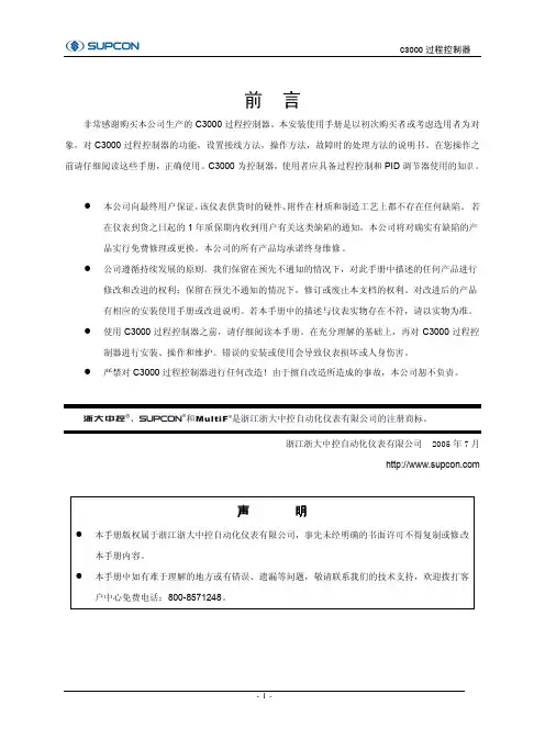
2011023-041-091-06控制屏转换开关闭合表-Model
- 格式:pdf
- 大小:37.93 KB
- 文档页数:1


Multi-contact, Labor-saving, Environment-friendly, Next-generation Safety-door Switch•Lineup includes three contact models with 2NC/1NO and 3NC contact forms and MBB models in addition to the previous contact forms 1NC/1NO, and 2NC.•M12-connector models are available, saving on labor and simplifying replacement.•Standardized gold-clad contacts provide high contact reliability.Applicable to both standard loads and micro -loads.•Variety of metallic heads available.•Conforms to ISO 14119.Model Number StructureModel Number LegendSwitch (Standard type)1.Conduit/Connector size 1:Pg13.5 (1-conduit)2:G1/2 (1-conduit)4:M20 (1-conduit)6:G1/2 (2-conduit)8:M20 (2-conduit)9:M12 connector (1-conduit)2.Built-in SwitchA:1NC/1NO (slow-action)B:2NC (slow-action)C:2NC/1NO (slow-action)D:3NC (slow-action)E:1NC/1NO (MBB contact)F:2NC/1NO (MBB contact)3.Head Mounting DirectionF:Four mounting directions possible (Front-side mounting atshipping)/plasticD:Four mounting directions possible (Front-side mounting atshipping)/metal Note:An order for the head part or the switch part alone cannot beaccepted. (The Operation Key is sold separately.)Switch (High pull-force type)1.Conduit size2:G1/2 (1-conduit)4:M20 (1-conduit)2.Built-in SwitchA:1NC/1NO (slow-action)B:2NC (slow-action)C:2NC/1NO (slow-action)D:3NC (slow-action)Operation Key1.Operation Key Type 1:Horizontal mounting 2:Vertical mounting3:Adjustable mounting (Horizontal)5:Adjustable mounting (Horizontal/Vertical)Be sure to read the “Safety Precautions” on page 13.Slide keysSafety Door S w itchsFor the most recent information on models that have been certified for safety standards, refer to your OMRON website.123D4NS-@@@1 2D4NS-@@F-SJ1D4DS-K @Ordering InformationSwitches (Operation Keys are sold separately.)Consult with your OMRON representative when ordering any models that are not listed in this table.*Models with Korean S-mark certification.TypeContact configurationConduit opening/ConnectorModel 1-ConduitSlow-action1NC/1NOPg13.5D4NS-1AF *G1/2D4NS-2AF *M20D4NS-4AF 2NCPg13.5D4NS-1BF *G1/2D4NS-2BF *M20D4NS-4BF 2NC/1NOPg13.5D4NS-1CF *G1/2D4NS-2CF *M20D4NS-4CF 3NCPg13.5D4NS-1DF *G1/2D4NS-2DF *M20D4NS-4DF Slow-action MBB contact1NC/1NOPg13.5D4NS-1EF G1/2D4NS-2EF M20D4NS-4EF 2NC/1NOPg13.5D4NS-1FF G1/2D4NS-2FF M20D4NS-4FF 2-ConduitSlow-action1NC/1NO G1/2D4NS-6AF M20D4NS-8AF 2NCG1/2D4NS-6BF M20D4NS-8BF 2NC/1NOG1/2D4NS-6CF M20D4NS-8CF 3NC G1/2D4NS-6DF M20D4NS-8DF Slow-action MBB contact1NC/1NOG1/2D4NS-6EF M20D4NS-8EF 2NC/1NOG1/2D4NS-6FF M20D4NS-8FF 1-Conduit, with connectorSlow-action 1NC/1NO M12 connector D4NS-9AF 2NC D4NS-9BF Slow-action MBB contact1NC/1NO D4NS-9EF 1-Conduit(High pull-force type)Slow-action1NC/1NO G1/2D4NS-2AF-SJ *M20D4NS-4AF-SJ *2NCG1/2D4NS-2BF-SJ *M20D4NS-4BF-SJ *2NC/1NO G1/2D4NS-2CF-SJ *M20D4NS-4CF-SJ *3NCG1/2D4NS-2DF-SJ *M20D4NS-4DF-SJ *: Models w ith certified direct opening contacts.Operation KeysSlide KeysAppearanceSpecificationsContentsModelApplicable DoorSwitchWeight: 422 g Mechanical durability: 20,000 operations min.Slide Key: 1Auxiliary mounting bracket: 1Receptacle bracket: 1D4NS-SK01D4NS1-conduit typeWeight: 2,800 g Mechanical durability: 20,000 operations min.Slide Key: 1D4NS mounting tool: 1Inner lever: 1Inner lever mounting screws: 2Door Switch mounting one-way screws: 2Switch protective cover: 1Switch protective cover screws: 4Disable-prevention cover(already mounted on Slide Key): 1D4NS-SK30D4NS1-conduit typenting ntingSlide Keys D4NS-SK01ConfigrationIdeal for 20 x 20-mmal u min u m frame doorsD4N S 1-cond u it typeD4NS-SK01Can be mounted directly to a20 x 20 mm aluminum frame.Note: T he D4NS-9AF Safety-door Switch(with M12 connector) is sold separately.Can be mounted directly to a20 x 20 mm aluminum frame.Release door lock.1Open door.2Close door.3Lock door.4Note: A ssess risk before implementingsafety measures for the equipment.D4NS-SK30ConfigrationANSI/RIA R15.06-1999 8.4 Protection of personnel within the safeguarded spacePersonnel required to perform tasks within the safeguarded space shall be protected by:a) Preventing the re-initiation of any motion or hazardous process while personnel are within the safeguarded space, for example locking a gate open;For safety meas u res on large doorsD4N S 1-cond u it typeD4N S-SK30Open door.Close door.Magnetic catches pre v ent the operator from accidentally opening the door.Operation displayw indo w lets yo u v is u confirm Key insertion.L-shaped key g u ard pre v ents Key from b eing damaged.Open door.Set the disa b le- v ention co v er ith a pad lock toD4NS/D4NS-SK SpecificationsStandards and EC DirectivesConforms to the following EC Directives:•Machinery Directive•Low Voltage Directive•EN50047•EN60204-1•EN ISO 14119•GS-ET-15Certified Standards*1.Certification for CSA C22.2 No. 14 is authorized by the UL mark.*2.Only certain models have been certified.Certified Standard RatingsTÜV (EN60947-5-1), CCC (GB14048.5)Note:Use a 10 A fuse type gI or gG that conforms to IEC60269 as ashort-circuit protection device. This fuse is not built into theSwitch.UL/CSA (UL508, CSA C22.2 No. 14)A300Q300 Characteristics Note:1.The above values are initial values.2.The Switch contacts can be used with either standard loadsor microloads. Once the contacts have been used to switcha load, however, they cannot be used to switch smallerloads. The contact surfaces will become rough once theyhave been used and contact reliability for smaller loads maybe reduced.*1.The degree of protection is tested using the method specified by the standard (EN60947-5-1). Confirm that sealing properties are sufficient for the operating conditions and environmentbeforehand. Although the switch box is protected from dust or water penetration, do not use the D4NS in places where foreign material may enter through the key hole on the head, otherwise Switch damage or malfunctioning may occur.*2.The durability is for an ambient temperature of 5 to 35°C and an ambient humidity of 40% to 70%. For more details, consult your OMRON representative.*3.Do not pass the 3 A, 250 VAC load through more than 2 circuits. *4.These figures are minimum requirements for safe operation.*5.This value will vary with the switching frequency, environment, and reliability level. Confirm that correct operation is possible with the actual load beforehand.Certification body Standard File No.TÜV SÜD EN60947-5-1(certified direct opening)Consult yourOMRON representativefor details.UL *1UL508, CSA C22.2 No.14E76675 CQC (CCC)GB14048.52003010305077330KOSHA *2EN60947-5-1Consult your OMRON representativefor details.Item UtilizationcategoryAC-15DC-13Rated operating current (I e) 3 A0.27 A Rated operating voltage (U e)240 V250 VRated voltage Carry currentCurrent (A)Volt-amperes (VA)Make Break Make Break120 VAC10 A 6067,200720240 VAC303Rated voltage Carry currentCurrent (A)Volt-amperes (VA)Make Break Make Break125 VDC2.5 A 0.550.556969250 VDC0.270.27Degree of protection *1IP67 (EN60947-5-1) Durability *2Mechanical<Standard type>1,000,000 operations min.<High pull-force type>100,000 operations min.Electrical<Standard type>500,000 operations min. (3 Aresistive load at 250 VAC) *3300,000 operations min. (10 Aresistive load at 250 VAC)<High pull-force type>100,000 operations min. (10 Aresistive load at 250 VAC) Operating speed0.05 to 0.5 m/sDirect opening force *4<Standard type>60 N min.<High pull-force type>80 N min.Direct opening travel *410 mm min.Contact resistance25 mΩ max.Minimum applicable load *5 1 mA resistive load at 5 VDC (N-level reference value)Rated insulation voltage (U i)300 VRated frequency50/60 HzProtection against electricshockClass II (double insulation)Pollution degree (operatingenvironment)3 (EN60947-5-1)Impulsewithstandvoltage(EN60947-5-1)Betweenterminals ofsame polarity2.5 kVBetweenterminals ofdifferentpolarity4 kVBetween eachterminal andnon-currentcarryingmetallic parts6 kVInsulation resistance100 MΩ min.Contact gap 2 × 2 mm min.VibrationresistanceMalfunction10 to 55 Hz, 0.75 mm singleamplitudeShockresistanceDestruction1,000 m/s2 min.Malfunction300 m/s2 min.Conditional short-circuitcurrent100 A (EN60947-5-1)Conventional free air thermalcurrent (I th)10 A (EN60947-5-1)Ambient operatingtemperature−30 to 70°C (with no icing) Ambient operating humidity95% max.Weight Approx. 96 g (D4NS-1CF)Structure and NomenclatureStructureContact FormDiagrams Show State with Key Inserted.*MBB (Make Before Break) contacts have an overlapping structure, so that before the normally closed contact (NC) opens, the normallyopen contact (NO) closes.Note: The 2-cond u it models ha v e the same terminal arrangement.HeadThe head can b e mo u nted in fo u r directions.Sealing propertiesThe s w itch casing ens u res IP67D4NS-@C @, D4NS-@D @, D4NS-@F @, D4NS-@CF-SJ, D4NS-@DF-SJD4NS-@A @, D4NS-@B @, D4NS-@E @, D4NS-@AF-SJ, D4NS-@BF-SJDimensions(Unit: mm)Dimensions and Operating Characteristics1-Conduit Models2-Conduit Models1-Conduit Connector ModelsNote:1.Unless otherwise specified, a tolerance of ±0.4 mm applies to all dimensions.2.There are fluctuations in the contact ON/OFF timing for Switches with multiple poles (2NC, 2NC/1NO, or 3NC). Confirm performance beforeapplication.D4NS-1@F D4NS-2@F D4NS-4@F D4NS-2@F-SJ D4NS-4@F-SJ0.05R 0w o, 4+0.15 dia. holes * Al w ays maintain the a b o v e operating characteristics for safe u se.b oth sides)D4NS-6@FD4NS-8@F0 +0.15 dia. holes * Al w ays maintain the a b o v e operating characteristics for safe u se.× 1D4NS-9@F0 Two, 4+0.15 dia. holes depth: 5* Always maintain the above operating characteristics for safe use.Operation KeysSlide KeysD4NS-SK01D4NS-SK30Open DoorClosed DoorWith Operation Key Inserted (Relationship between Insertion Radius and Key Hole)Note:Unless otherwise specified, a tolerance of ±0.4 mm applies to all dimensions.D4NS-1@F + D4DS-K1(with Front-inserted Operation Key)±1.2001.D4NS-1@F + D4DS-K1(with Top-inserted Operation Key)D4NS-1@F + D4DS-K2(with Front-inserted Operation Key)1.200D4NS-1@F + D4DS-K2(with Top-inserted Operation Key)Note:Unless otherwise specified, a tolerance of ±0.4 mm applies to all dimensions.D4NS-1@F + D4DS-K3(with Front-inserted Operation Key)±1.±1.200Horizontal key insertion D4NS-1@F + D4DS-K3(with Top-inserted Operation Key)D4NS-1@F + D4DS-K5(with Front-inserted Operation Key)51.9 to 54.4±1.R ≥50≥ 50radius R ≥ 50D4NS-1@F + D4DS-K5(with Top-inserted Operation Key)<Safety-door Switch D4NS>!CAUTION•Do not use the Switch submersed in oil or water or in locations continuously subject to splashes of oil or water. Doing so may result in oil or water entering the Switch. (The IP67 degree of protection of the Switch specifies the amount of water penetration after the Switch is submerged in water for a certain period of time.)•Always attach the cover after completing wiring and before using the Switch. Also, do not turn ON the Switch with the cover open. Doing so may result in electric shock.•Do not switch circuits for two or more standard loads (250 VAC, 3A). Doing so may adversely affect insulation performance.Stopper InstallationDo not use a Switch as a stopper. Be sure to install a stopper as shown in the following illustration to ensure that the base of theOperation Key does not strike the Head, and adjust the stopper to be within the setting zone (0.5 to 3 mm) of the base of the Operation Key. Do not subject the Switch to a shock that exceeds the Switch's shock resistance of 1,000 m/s 2.The Switch contacts can be used with either standard loads or microloads. Once the contacts have been used to switch a load, however, they cannot be used to switch smaller loads. The contact surfaces will become rough once they have been used and contact reliability for smaller loads may be reduced.tool while pressing down on the screw head, do not continue turning the screw past the point where the threads disengage. Doing so may strip the end of the threads.Mounting Holes•Use M4 screws and spring washers to mount the Switch and Operation Key, and tighten the screws to a suitable torque. To ensure safety, use screws that cannot be easily removed or another means to prevent the Switch and Operation Key from easily being removed.•As shown below, two studs with a maximum height of 4.8mm anda diameter of 4 mm can be provided, the studs inserted into the holes on the bottom of the Switch, and the Switch secured at four locations to increase the mounting strength.•Set the Operation Key so that it is within 1 mm of the center of the key hole. If the Operation Key is offset or at an angle, accelerated wear or breaking may result.•Observe the specified insertion radius for the Operation Key and insert it in a direction perpendicular to the key hole.Electric shock may occasionally occur.Do not use metal connectors or metal conduits.Precautions for Safe UsePrecautions for Correct Use−0.05−0.15Switch Mounting Holes and Studs •1-Conduit Modules2.5 -0.05-0.15 dia.Height: 4.8 max.4-0.15 dia.Height: 4.8 max.•2-Conduit Moduleso, M4o, M4o, M4Operation Key Mounting Holes•Horizontal/Vertical Mounting (D4DS-K1/-K2)•Horizontal Adjustable Mounting (D4DS-K3)•Horizontal/Vertical Adjustable Mounting (D4DS-K5)D4NS/D4NS-SKHead Direction•The rotation of the Switch head may be adjusted to any of the four directions by loosening the head mounting screws at the four corners of the head. Make sure that no foreign materials enter through the head.•Do not insert or remove the Operation Key with the Switch head removed. Doing so may make it impossible to insert the Operation Key.Securing the DoorWhen the door is closed (with the Operation Key inserted), theOperation Key may exceed the set zone because of, for example, the door's own weight, machine vibration, or the door cushion rubber. Secure the door with a stopper so that the Operation Key remains within the set zone.WiringWiring•When connecting with insulation tubes and M3.5 crimp terminals, connect the terminals as shown in the following figure and wire without overriding to the case and the cover. Adequate conductor size is AWG 20 to AWG18 (0.5 to 0.75 mm 2).Prepare lead wires using the lengths given in the following diagrams. If lead wires are too long, they will press against the cover causing the cover to not close properly.•Do not push the crimp terminal and the likes into the opening between the parts to prevent the case from being broken and deformed.•Use terminals having the thickness of 0.5 mm or less to avoid the contact between the terminal and the Switch case inside.<Reference>The crimp terminals listed below have a thickness of 0.5 mm or less.J.S.T is a Japanese manufacturer.Pin arrangement of connector type•Suitable socket is XS2F-D421 series (OMRON).•Refer to the Connector Catalog for corresponding Socket pin numbers and lead wire colors.Socket Tightening (Models with Connectors)•Turn the tightening screws on the Socket by hand and tighten them until the gap between the Socket and Plug essentially disappears.•Make sure that the Socket’s connector is tightened securely, otherwise the rated degree of protection (IP67) of the D4NS may not be maintained, or the Socket connector may be loosened by vibration.Conduit Opening•Use cables with suitable diameters for the connector being used.•When wiring, place the enclosed cap screw on unused conduit openings (for 2-Conduit Switches) and tighten them to the suitable tightening torque.Recommended ConnectorsUse the connector with thread section of 9 mm long or less. If a connector with a longer thread section is used, the protruding part may interfere with the other parts inside the body. Use the connectors listed below to ensure IP67 degree of protection.When use LAPP's products, use together with a Seal Packing which is sold separately (Type names, JPK-16, GP-13.5, or GPM20) and tighten with proper tightening torque.•LAPP is a German manufacturer.1-Cond u2-Cond u±2 mmManufacture TypeJ.S.T. Mfg Co.FN0.5-3.7 (F Type)N0.5-3.7 (Straight Type)Size Manufacture Model Applicable cablediameter G1/2LAPP ST-PF1/25380-1002 6.0 to 12.0mm Pg13.5LAPP S-13.55301-5030 6.0 to 12.0mm M20LAPPST-M20 × 1.55311-10207.0 to 13.0mmt: 0.5 dz dia.:D dia.:B:L:19 mm F:I: 8Correct Incorrect1 324D4N S-9BF (2N C)1 (11) 3 (31)D4N S-9AF (1N C/1N O)D4N S-9EF (1N C/1N O (MBB))Pin N o. (Terminal N o.)Z bD4NS/D4NS-SK<Slide Keys D4NS-SK01/SK30>•Do not drop the Switch. Doing so may prevent the Switch from functioning to full capacity.•Mount the Switch securely to prevent it from falling. Otherwise, injuries may occur.•Do not attempt to disassemble or modify the Switch. Doing so may cause the Switch to malfunction.•Make sure that the gap between the short bolt and guide is (±3 mm. Otherwise, excessive wear or damage may cause malfunction.•To ensure safety, do not operate the Switch with anything other than a Slide Key.•Be careful to avoid pinching your hand when operating the Switch.•Be sure to mount the Switch protective cover. Otherwise, your hand may be injured by being pinched between the shot bolt and Switch when closing the door with your hand on the Switch.•When opening the door, be sure to lower the disable-prevention cover into position, attach a padlock, or take other steps to prevent other people from operating the Switch.•The durability of the Switch is greatly influenced by the switching conditions. Always test the Switch under actual working conditions before application and use it in a switching circuit for which there are no problems with performance.•The user must not maintain or repair equipment incorporating the Switch. Contact the manufacturer of the equipment for any maintenance or repairs required.•Do not shut the door while the shot bolt is extended. The Switch may be damaged, preventing proper operation.•Do not apply excessive force in the direction of the slide. This may damage the product and cause it to malfunction.•Insert the slide handle until the red operation indicator is completely displayed in the operation display window.•Loose screws may result in malfunction. Use washers and tighten the screws to the specified torques. Also, when mounting the Switch to a door for disable-prevention purposes, purchase and use tamper-resistant screws.Tightening Torque•Use the D4NS-SK30 only with the D4NS Safety-door Switch head in the direction shown below.Technical Specifications•Do not store the Switch where corrosive gases (e.g., H 2S, SO 2,NH 3, HNO 3, or CL 2) or dust are present, or in locations subject to high temperature or humidity.•Perform maintenance inspections periodically.•This product is for use only with OMRON Safety-door Switches. Do not use it with door switches made by other manufacturers.Mounting Holes (Unit: mm)D4NS-SK30AssemblySwitch partD4NS-SK30Handle partD4NS-SK30Incorrect operation may cause injury. Also, the product is designed to be mounted so that it slides horizontally. Do not mount the product in a vertically sliding configuration.(excluding the D4NS-SK01)Precautions for Safe UsePrecautions for Correct UseSlide Key mounting screw (M6) 6.0 to 7.0 N·m Switch mounting screw (included with product)0.5 to 0.7 N·m Switch protective covermounting screw (included with product)1.2 to 1.4 N·m Lever mounting screw (included with product)1.2 to 1.4 N·mN ormal Ins u fficient insertionOperation display w indo wD4NS-SK30Ambient operating temperature −10 to 55°C (with no icing)Ambient operating humidity95% max.Mechanical durability 20,000 operations min.WeightApprox. 2.8 kg(not including D4NS Safety-door Switch)Operation KeyS w itch protecti mo u nting scre Fo u r, M4 × 6v ention co v erideS w itch mo u (one-w ay scre w )T w o, M4 × 25T w o, M4 × 8Terms and Conditions of SaleCertain Precautions on Specifications and UseOMRON CANADA, INC. • HEAD OFFICEToronto, ON, Canada • 416.286.6465 • 866.986.6766 • OMRON ELECTRONICS DE MEXICO • HEAD OFFICEMéxico DF • 52.55.59.01.43.00 •01-800-226-6766•**************OMRON ELECTRONICS DE MEXICO • SALES OFFICEApodaca,N.L.•52.81.11.56.99.20•01-800-226-6766•**************OMRON ELETRÔNICA DO BRASIL LTDA • HEAD OFFICE São Paulo, SP , Brasil • 55.11.2101.6300 • .brOMRON ARGENTINA • SALES OFFICE Cono Sur • 54.11.4783.5300OMRON CHILE • SALES OFFICE Santiago • 56.9.9917.3920OTHER OMRON LATIN AMERICA SALES 54.11.4783.5300Authorized Distributor:C23I -E-02 07/15 Note: Specifications are subject to change.© 2015 Omron Electronics LLC Printed in U.S.A.Automation Control Systems• Machine Automation Controllers (MAC) • Programmable Controllers (PLC) • Operator interfaces (HMI) • Distributed I/O • Software Drives & Motion Controls• Servo & AC Drives • Motion Controllers & Encoders Temperature & Process Controllers • Single and Multi-loop ControllersSensors & Vision• Proximity Sensors • Photoelectric Sensors • Fiber-Optic Sensors • Amplified Photomicrosensors • Measurement Sensors • Ultrasonic Sensors • Vision SensorsIndustrial Components• RFID/Code Readers • Relays • Pushbuttons & Indicators• Limit and Basic Switches • Timers • Counters • Metering Devices • Power SuppliesSafety• Laser Scanners • Safety Mats • Edges and Bumpers • Programmable Safety Controllers • Light Curtains • Safety Relays • Safety Interlock SwitchesOMRON AUTOMATION AND SAFETY • THE AMERICAS HEADQUARTERS • Chicago, IL USA • 847.843.7900 • 800.556.6766 • OMRON EUROPE B.V. • Wegalaan 67-69, NL-2132 JD, Hoofddorp, The Netherlands. • +31 (0) 23 568 13 00 • www.industrial.omron.eu。